Journal of Thermodynamics & Catalysis
Open Access
ISSN: 2157-7544
ISSN: 2157-7544
Review Article - (2017) Volume 8, Issue 3
Keywords: Vinyl chloride; Dichloroethane; Pyrolysis; Conversion; Selectivity; Coke formation; Kinetics; Initiation; Inhibition; Simulation; Energy saving
Vinyl chloride, (world-recognized abbreviation-VCM-Vinyl Chloride Monomer) is the unique and most large-scale chemical industry product of complex processing of mineral and organic raw materials-sodium chloride and petrol. In 2015 its global production reached 40 million tons. Up to 98% of all produced VCM is used for the production of polyvinyl chloride (PVC), the most important polymer material that has been produced in industrial scale for more than 80 years and together with polyethylene and polypropylene is in the top three most common polymers.
For the first time, VCM was obtained in 1835 by the German chemist Justus von Liebig and his disciple, the French chemist Henri Victor Regnault, via the reaction of alcohol solution of caustic potassium with 1,2-dichloroethane (hereinafter referred to as EDC) [1]. In 1902, Blitz received VCM by catalytic EDC decomposition over pumice at a red heat temperature, and in 1908 - Senderens by EDC decomposition over dehydrated alumina at 370°C [2].
The real prerequisites for the industrial production of VCM were the reactions for VCM obtaining, discovered virtually simultaneously in 1912-1913, by acetylene hydrochlorination in the gas and liquid phases (Fritz Klatte, Germany) and its photopolymerization (Ostromyslensky, Russia). In 1929 the first industrial complex for VCM-PVC production was constructed in the city of Rheinfelden (Germany).
Beginning from the mid-1960s, the so-called balanced method of VCM production became widespread. Its essence is that VCM is obtained by EDC pyrolysis at 480-500°C, while the hydrogen chloride formed is directed to oxidative chlorination (oxychlorination) of ethylene with the production of additional EDC. In this case, the chlorine introduced into the system (directly-at the stage of direct liquid-phase chlorination of ethylene, as well as in the form of hydrogen chloride at the stage of ethylene oxychlorination) is almost completely bound to the target products.
In the process of oxychlorination of ethylene, there is a significant number of publications in the literature; we note [2-7] among them. The conformities of the process of direct chlorination of ethylene are described in detail in [2,5].
Pyrolysis of EDC to obtain the target product VCM is carried out in tubular furnaces. In most installations, the EDC conversion per pass is 50-55%. To achieve such conversion, the temperature of the gases leaving the reaction coil of the furnace is maintained at approximately 500°C. The pressure in the system is usually 2-2.5 MPa. The temperature profile along the length of the coil depends on the design of the furnace and the set process conditions. At high temperatures, the degree of pyrolysis increases, which, however, leads to increasing of the yield of organic by-products, as well as the hard carbon deposits on the walls of the coil. To clean the coil, it is necessary to regenerate it periodically. Virtually all of the EDC, remained unreacted in the furnaces, is separated and returned to the process again. In this case, an optimal balance of VCM throughput, its yield and purity with the cost of re-separation of EDC and downtime is established [3]. It is the gas phase process that makes it possible to obtain anhydrous hydrogen chloride, which is then utilized in the stage of oxychlorination of ethylene. The process of dehydrochlorination of EDC can be thermal only-the temperature in this case, as mentioned above, is 480-500°C; initiated the temperature is 400-450°C; or catalytic-the temperature is 325-380°C.
In this review, we consider data obtained at different time periods during laboratory researches of the process of EDC pyrolysis, as well as the main conformities of industrial use of this process.
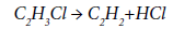
Pyrolysis of EDC is an endothermic process proceeding upon the total reaction:
C2H4Cl2→C2H3Cl+HCl-73 kJ/mol (1)
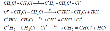
Below 350°C the rate of volume reaction is extremely low, and at 250°C EDC does not decompose at all. Pyrolysis of EDC is a free-radical chain process, which includes:
Chain initiation
 (2)
(2)
dichloroethane
Chain propagation and growth
Cl*+CH2Cl-CH2Cl→CH2Cl-C*HCl+HCl
Dichloroethane (3)
CH2Cl-C*HCl→CH2=CHCl+Cl*
Vinylchloride(4)
3. Termination of chain
CH2Cl-C*HCl+Cl→CH2Cl-CHCl2
1,1,2-trichloroethane (5)
2CH2Cl-C*HCl→CH2Cl-CHCl-CHCl-CH2Cl
1,2,3,4-tetrachlorobutane (6)
2CH2Cl-C*HCl→CHCl=CHCl+CH2Cl-CH2Cl
1,2-dichloroethylene (7)
Cl*+wall→termination (8)
Thus, the process begins with the breakdown of the C-Cl bond in the EDC molecule, followed by chain propagation-H atom abstraction with Cl* radical from the EDC molecule and the molecular decomposition of the 1,2-dichloroethyl radical; chain termination occurs homogeneously when radical recombination. The Cl* radical guides chain reactions of EDC, which explains, in particular, the acceleration or slowing down of the reaction by various additives, which, participating in the chain, promote its nucleation or termination.
By-products are formed, mainly in the case of overheating above 500°C. Particularly undesirable is the process of thermal decomposition of the formed VCM. This reaction at temperatures exceeding 500°C proceeds at a noticeable rate with the formation of acetylene:
CH2=CHCl→HC≡CH+HCl
Acetylene (9)
Further, a number of by-products are formed from acetylene, in particular, benzene, vinylacetylene, chloroprene, methyl chloride, etc. [2]. Some of the by-products are precursors in the formation of solid carbon deposits, the so-called “coke”.
The pressure, temperature and quality of EDC fed to pyrolysis are the main factors that influence the selectivity of the process. In modern industrial installations, the selectivity is usually at the level of 99%. The amount of organochlorine waste generated at this stage, however, is up to 50% of the total amount of organic waste in a balanced process and exceeds the corresponding amount formed in other stages of the process direct and oxidative chlorination of ethylene [2]. This indicates the need to use a number of techniques helping maintain the selectivity of the EDC pyrolysis process at the required level.
The pyrolysis process of EDC is reversible; its peculiarity is that in the reverse reaction of VCM and hydrogen chloride, according to the Markovnikov rule not EDC is formed, but its isomer, 1,1-dichloroethane.
The change in temperature and pressure can have a significant effect on the equilibrium composition of the pyrolysis products [2,8-10].
With an increase in pressure from 0.1 to 4 MPa, the equilibrium conversion of EDC somewhat decreases, but at temperatures above 600 K, even at a pressure of 4 MPa, the equilibrium conversion of EDC exceeds 90%. With an increase in pressure the equilibrium yield of VCM and acetylene slightly decreases, while that of 1,1-dichloroethane slightly increases.
With an increase in temperature, the output of VCM initially increases, and then, after reaching the maximum, begins to decrease. With an increase in pressure, the maximum yield of VCM shifts to higher temperatures: for a pressure of 0.1 MPa, the maximum yield (more than 99%) is possible at 500-600 K, for 0.5 MPa at 600 K, for 2-4 MPa at 700 K. Under these conditions, the equilibrium yield of acetylene remains equal to less than 1%.
In general, for conditions providing technologically acceptable process parameters (T=600-800 K, P=1.5-3.0 MPa), there are no thermodynamic limitations.
The beginning of systematic researches of the pyrolysis process of EDC dates back to the end of the 1940s, when the kinetic conformities of the process were first described by Barton et al. [11-14]. In [11,12], the pyrolysis of EDC was investigated in a tubular flow reactor made of refractory glass with a diameter of 15 mm and a length of 750 mm in the temperature range of 362-485°C. It was shown that the rate of the pyrolysis is described by a first order equation.
As a result of experiments in the reactor with walls covered with a carbon film, the authors obtained the following expression for the reaction rate constant:
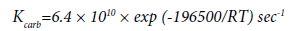 (10)
(10)
This expression differs markedly from the expression for the rate constant obtained by Barton for the reactor with clean walls:
 (11)
(11)
At 758 K, kcarb/kcl=0.08; at 635 K, kcarb/kcl=6 × 10-3. Thus, when the walls are covered with the carbon film, the initiating capacity of the surface is significantly reduced.
According to [12], the presence in the system of small concentrations of propylene (less than 0.1%) significantly reduces the rate of pyrolysis of EDC. The authors of [12] interpret this fact as confirmation of the radical chain mechanism of the process. As opposed to EDC, the pyrolysis of ethyl chloride and 1,1-dichloroethane is not inhibited by propylene; the authors [13] explain this fact from the standpoint of a different mechanism of decomposition of the raw compound, in comparison with EDC. This is also indicated by the absence of an induction period of the reactions. It is assumed that the dehydrochlorination of these compounds proceeds upon a monomolecular mechanism.
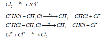
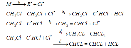
Howlett [14] proposed the following scheme for the free-radical chain dehydrochlorination mechanism of EDC:
On the basis of this mechanism, using the method of stationary
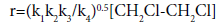 (12)
(12)
The values of reaction rate constants are as follows:
k1=1013exp(-292600/RT) sec-1
k2=108.62exp(-20900/RT) l mol-1 sec-1
k3=1010exp(-92000/RT) sec-1
k4=1010exp(-12500/RT) l mol-1 sec-1
The general expression for the rate constant corresponds to equation (10).
Doreiswami [9] studied the kinetics of the EDC thermal dehydrochlorination in the temperature range of 400-500°C, using a flow reactor. Assuming the first order of the reaction, the author deduced that the reaction rate constant for conversion degrees of less than 80% is expressed by the following equation:
k=1.49 × 10²⁰ × exp(-59000/RT) sec-1 (13)
In contrast to Barton, Doreiswami carried out experiments with raw EDC (the distillation range of the latter is 82-84°C at 760 mmHg) and in his calculations, did not take into account the effect of an increase in the volume of the reaction mixture, which casts some doubt on the validity of the data obtained.
According to the data obtained by Kitabatake et al. [15], the rate constant of the first-order reaction in the temperature range of 470- 530°C is described by the following relationship:
k=1.15 × 10⁷ × exp (-114500/RT) sec-1
Very close results were obtained by Takahashi [16].
k=3.3 × 10⁷ × exp (-121800/RT) sec-1
The authors of [16] did not find out any noticeably affect of the pressure change from 1 to 8 atm upon the reaction rate, while the surface-to-volume ratio (S/V) had a significant effect on the rate: the reaction rate is proportional to S/V to the power of ½.
Sonin [10], when studying the process in a glass gradientless reactor, obtained the following expression for the reaction rate constant:
k=6.47∙109∙exp (-154100/RT) sec-1
Thus, all the researchers agree that the reaction of thermal pyrolysis of EDC obeys the first-order equation. The difference in the values of the pre-exponential factors and the activation energies may be explained by a number of factors: the diameter and material of the reactor, the purity of the EDC used, the degree of carbonization of the reactor walls, etc. [17-22].
An important characteristic that has a significant effect on the rate of pyrolysis of EDC and its selectivity is the ratio between the homogeneous and heterogeneous components, i.e., the ratio of the reactor surface to its volume (S/V). According to Kitabatake et al. [15], the rate of the reaction of EDC dehydrochlorination somewhat decreases with increasing the diameter of the reaction tube, i.e., with a decrease in S/V. A similar opinion was held by Semenov [23]. However, in [24], it was shown using the calorimetry method that there is no correlation between the rate of decomposition of EDC in clean vessels and the S/V ratio. Based on this, the authors of [24] conclude that the given reaction is not heterogeneous, but initiates on the surface and propagates in volume. In contrast, Barton [11] showed that the reaction rate decreases when it is carried out on a glass packing, i. e. with an increase in the S/V ratio. This seems quite natural, because when using a packing, the relative value of the surface increases drastically and under these conditions the wall begins to inhibit the chain process, since not only the nucleation but also the termination of chains occurs on the surface.
According to the data of [10], the results obtained using reaction tubes of different diameters, 21, 50 and 60 mm, do not show a clear dependence in the change in the conversion at the same values of the linear flow velocity. At the same time, the reaction rate increases mainly due to an increase in the gas flow velocity characterized by the Reynolds value of up to Re=0.8÷1 × 10⁵. Further increase in the flow velocity has virtually no effect on the reaction rate.
Detailed investigations of the effect of the surface on the rate of the EDC pyrolysis in a wide range of S/V ratios were made by Holbrook et al. [25]. The kinetic data obtained by the authors of [25] under the conditions of the pyrolysis of EDC in reactors with low and high S/V values show that for S/V values of 1.3-1.4 cm-1 the total order of the reaction is in the range 2.5-3, and the activation energy is of the order of 300 kJ/mol. At S/V=37.4 cm-1, the order of the reaction is 1.5, and the activation energy is 140 kJ/mol. The authors of [25] expanded the mechanism of the process proposed by Howlett [14], introducing into it the reaction of termination at the walls of the reactor:
Cl+S→SCl (17)
C2H3Cl2+S→C2H3Cl2S (18)
A hypothesis on autocatalysis by means of a chemisorbed chlorine atom was also proposed in [25]. The authors indicate that in a reactor filled with a glass packing, i.e., at high S/V values, the dechlorination of EDC proceeds to form ethylene and adsorbed chlorine:
C2H4Cl2 + S ⇔ (C2H4Cl2 )s (19)
(C2H4Cl2)s→C2H4+(Cl2)s (20)
The reaction of dechlorination of EDC has half the order; the activation energy is 196 kJ/mol. The desorption stage of chlorine is described by equation (21):
(Cl2)s→Cl+SCl (21)
where the fragment SCl is the main element determining the autocatalytic nature of the process. In general, according to the data of [25], the initial rate decreases substantially as the S/V ratio increases.
The authors of [26] proposed a model for the pyrolysis of EDC, which includes both homogeneous and heterogeneous components. It is shown that homogeneous and heterogeneous initiation of chain have the same rate. By analogy with [25], the authors of [26] believe that the heterogeneous component plays the most important role in the reactions of chain termination. It is also indicated that for small S/V values of 1.04 cm-1, the presence of the heterogeneous factor reduces the rate of homogeneous decomposition of EDC by a factor of 5, and with an increase in S/V up to 10 cm-1, this decreasing becomes even more noticeable. The authors of [26] conclude that the limiting stages of the process are the initiation and termination of the chains just on the walls of the reactor.
The positive effect of increasing the S/V ratio upon the process rate was noted in [27]. When researching the process in the temperature range of 460-500°C it was shown that an increase in the surface by ~ 6% leads to an increase in the conversion of EDC in 1.1-1.5 times, and this effect is more pronounced with decreasing temperature.
The totality of the data presented in [11,24,25] shows that the total rate of the process of EDC dehydrochlorination is the sum of the monomolecular, radical-chain homogeneous and heterogeneous components, while the role of each them depends on the conditions of the process. An attempt was made [28] to investigate the pyrolysis of EDC under strictly homogeneous conditions. The authors indicate that such conditions can be ensured by using the adiabatic compression method. It is shown that in the temperature range of 920-1050 K and the typical process time periods of 10-2 sec., EDC participates only in the dehydrochlorination reaction with the formation of VCM. From the degree of conversion ~45%, traces of acetylene appear. The activation energy of the process is 65 kcal/mol (272 kJ/mol). Under the selected conditions, the dehydrochlorination reaction of EDC is monomolecular [28]. The rationale for this approach is a higher activation energy in comparison with the data of Barton and Howlett [13,14] by 9 kcal/mole and the absence of radical recombination products at the conversion rates of EDC up to 45%.
One of the possible ways to reduce energy costs for the pyrolysis of EDC may be a decrease in temperature. Provided that the high rate of the process and, consequently, the conversion of EDC is maintained, this can be achieved through the use of the so-called initiating additives. Such additives can include, for example, chlorine, carbon tetrachloride, hexachloroethane, as well as other compounds, in which C-Cl bond breakage energy is lower in comparison with that of EDC. Table 1 shows the values of the energy of C-Cl and Cl-Cl bond breakage for EDC and some initiators [17].
| Name | The produced radical or molecule | Breakdown energy, kJ/mol |
|---|---|---|
| carbon tetrachloride | C•Cl3 | 297 |
| hexachlorethane | CCl3C•Cl2 | 290 |
| 1,2-dichloroethane | CH2ClC•H2 | 335.1 |
| ?hlorine | Cl• | 242.4 |
Table 1: The C-Cl and Cl-Cl bond breakage energy for some compounds.
Since the reaction of EDC dehydrochlorination proceeds through a radical chain mechanism, the presence of initiators significantly increases its rate. One of the most effective initiators is chlorine, which has the bond breakdown energy of 60-80 kJ/mol lower than C-Cl bond breakdown energy in chloroethanes.
Thus, in the presence of a negligible amount of chlorine, the conversion of EDC drastically increases [18]. This is evident from Table 2. It should be noted that the conversion of EDC increases only in the temperature range 300-400°C.
| Chlorine,% wt. | Reaction temperature, °C | Conversion of EDC, % |
|---|---|---|
| – 0.5 0.5 0.5 |
400 370 350 300 |
2 70 50 30 |
Table 2: Effect of chlorine additives on EDC conversion as a function of temperature.
The initiating effects of other halogens were also investigated. Thus, Smolyan [19] determined by calculation that the initiating capacities of fluorine, chlorine, bromine and iodine differ drastically not only because of the difference in their degree of dissociation, but also because of the strength of the H-hal bond. The rate constant for the chain transfer reaction is the highest for fluorine, but it cannot be used as an initiator of the EDC pyrolysis process for obvious reasons.
The relative values of the process rate when using chlorine and bromine are comparable with each other and by two orders of magnitude higher than the corresponding values when using iodine as an initiator. Similar researches were carried out by Barton [11]; for the data see Table 3.
| Halogen, % wt. | Conversion of EDC, % |
|---|---|
| Chlorine 0.5 Bromine 0.5 Iodine 0.5 |
44 33 1 |
Table 3: Dependence of conversion of EDC on the nature of halogen.
The process of gas-phase dehydrochlorination of EDC, initiated by chlorine, has been studied by a number of researchers [10,11,16,19]. Barton et al. [11,16] came to the conclusion that the reaction rate is described by a following kinetic equation:
 (17)
(17)
i.e., the reaction is half the order with respect to initiator and the first with respect to EDC.
According to Barton [11], the expression for the rate constant has the following form:
k=1 × 1 × 103∙exp (-51000/RT) sec-1 (18)
According to Takahashi [16],
k=3.3∙103∙exp (-51800/RT) sec-1 (19)
Sonin [10] argues with the authors of [11,16]; according to Sonin the reaction rate of dehydrochlorination of EDC, initiated by chlorine, is described by the following equation:
 (20)
(20)
The difference in the form of kinetic equations entails a different understanding of the mechanism of the process by the authors. In the homogeneous dehydrochlorination of EDC, the reaction can proceed either through a monomolecular or a free-radical chain mechanism. Dehydrochlorination of a chlorinated derivative proceeds according to the molecular mechanism in the case when the chlorinated derivative itself or its decomposition products are the chain inhibitors.
Barton et al. [14,20-22] divided the studied by them chloroalkanes into two groups. The first group included chlorides, the decomposition of which is slowed down by the addition of propylene, acetaldehyde and is accelerated by the addition of chlorine and, consequently, proceeds according to the radical chain mechanism. This group includes 1,2-dichloroethane, 1,1,1-trichloroethane, 1,1,2-trichloroethane, 1,1,2,2-tetrachloroethane and 1,1,1,2-tetrachloroethane.
The second group includes chlorides, the rate of decomposition of which is not sensitive to additives of propylene, chlorine, etc. This group includes ethyl chloride, 1,1-dichloroethane, 1,2-dichloropropane, 2-chloropropane, propyl chloride, butyl chloride and isobutyl chloride. The authors believed that these chlorides decompose according to the true monomolecular mechanism directly to an olefin and hydrogen chloride. This is due to the fact that the reaction of the chlorine atom with a molecule of such chloride most likely forms a radical that is incapable of being converted to an olefin by removing a chlorine atom. In this case, chain decomposition is constrained, and the molecular decomposition gains an advantage. For example, the interaction of 1,1-dichloroethane with a chlorine atom more likely forms a radical C•Cl2-CH3, which is incapable of removing the chlorine atom.
Conversely, under these conditions EDC gives predominantly the radical CH2Cl-C•HCl, which is capable of giving off the chlorine atom and form VCM, which promotes the propagation of the chain reaction.
This approach corresponds to the general principles of the mechanism of chloroalkane dehydrochlorination proposed by Semenov [23].
Considering the mechanism of the reaction of the initiated dehydrochlorination of EDC, various authors [16,19] concluded that the most probable stage of a chain nucleation is the thermal decomposition of the initiator. T. Takahashi proposed a scheme for the mechanism of initiated dehydrochlorination of EDC, which is described as follows:
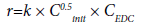
The equation of the chain reaction rate of the initiated dehydrochlorination of EDC derived on the basis of this mechanism has the form:
 (21)
(21)
and shows that the reaction has a common one-and-a-half the order and, in particular, half the order with respect to chlorine and the first order with respect to EDC.
Most authors who studied the decomposition of chloroalkanes and, in particular, EDC, believed that the chain reaction was initiated and terminated in volume, and the inhibitory effect of inhibitors was due to the termination of chains at them in the volume. Semenov [23] showed that the reaction initiates on the walls and propagates in the volume. The termination of chains occurs mainly on the wall, but partly in the volume as well. At the same time, Semenov notes that in the absence of the termination in the volume, the chain reaction of dehydrochlorination of EDC should proceed as that of the first order, if the chain termination is determined by the radical C•HCl- CH2Cl capture by the wall, and the chain nucleation on the wall occurs according to the reaction:

A comparison of the proposed mechanisms of thermal and initiated dehydrochlorination of EDC shows that the stage of the chain propagation does not differ in them. In principle, the stages of chain initiation do not differ as well, but the stages of termination differ from each other: if in the case of initiated dehydrochlorination of EDC chain termination involves the regeneration of the chlorine molecule (or in general, the initiator molecule), in the case of thermal dehydrochlorination of EDC recombination of chlorine and chloroethyl radicals occurs with the formation of neutral molecules.
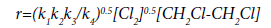
Such a difference in the mechanisms of chain termination is criticized in [10], in which it was suggested that the reaction of thermal dehydrochlorination of EDC should have the following mechanism:
This mechanism is similar to that proposed by K. Howlett, but differs somewhat from the mechanism proposed by Barton: the chain initiation stage is considered as the thermal decomposition of EDC molecule into two radicals, which most likely occurs in the wall layer and is more energetically favorable than proposed by Barton monomolecular decomposition of EDC into ethylene and a chlorine molecule [13].
The chain termination occurs only via recombination of chloroethyl radical and chlorine radical and does not follow the scheme of the chlorine radicals’ association with formation of molecular chlorine. This was proved by special experiments on the thermal dehydrochlorination of EDC, which showed that there was no free chlorine in the reaction products, and at the same time an appreciable amount of dichloroethylenes was found (about 5·10-3 moles per a mole of VCM) [10].
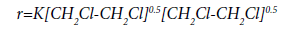
Even if we assume that free chlorine is still present in the reaction products, but in quantities below than the sensitivity of the method for its determination, then the likelihood of the reaction of termination upon the proposed scheme will be incomparably greater than that upon the scheme with the molecular chlorine formation. Therefore, the last reaction can be neglected.
Assuming that k3 >> k4.[Cl•], the equation of reaction rate of the thermal dehydrochlorination of EDC, corresponding to the proposed mechanism, has the following form:
 (22)
(22)
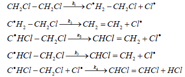
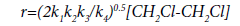
For the reaction of initiated dehydrochlorination of EDC, Sonin [10] proposed the following mechanism:
where M is a molecule of chlorine, hexachloroethane or another initiator.
In accordance with the proposed mechanism, the chain termination occurs mainly as a result of the interaction of chlorine with dichloroethyl radical, and not as a result of the recombination of chlorine radicals with the chlorine molecule formation.
Proceeding from the proposed mechanism and assuming that 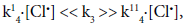 the reaction rate is described by the equation (23):
 (23)
(23)
where 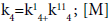 is a molecule of chlorine, hexachloroethane or EDC.
This mechanism also allows considering the reaction of EDC dehydrochlorination from the same positions, regardless of whether it occurs in the presence of the initiator or without it. Since during the thermal dehydrochlorination of EDC the role of the initiator giving rise to the chain is fulfilled by EDC itself, equation (23) may be represented in the following form:
 (24)
(24)
Which after simple conversion turns into equation (22), derived earlier for the reaction of the thermal dehydrochlorination of EDC.
Although both mechanisms are described experimentally, the general first order for both the reactions of thermal and initiated dehydrochlorination of EDC seems to be more logical and reliable than the change in the general order of the reaction from the first to the oneand- a-half one proposed by Barton et al. [10,29].
From a practical point of view, it is important to determine the minimum amount of chlorine necessary for the initiation. This is explained by the fact that chlorine introduced into the reaction zone forms ultimately chlorination products and, therefore, somewhat reduces the selectivity of the pyrolysis process. The author [10] showed that the initiation effect takes place in the range of chlorine concentrations of 0.3-1.1% mol. At chlorine content in the system of less than 0.3%, there is virtually no initiation.
Kinetic conformities of the chlorine conversion during the process of the initiated EDC pyrolysis under the assumption that chlorine, in addition to initiation, is consumed mainly in the reaction of the substitutive chlorination of EDC, can be written as follows [10]:
 (25)
(25)
The ratio of the rate constants of the reactions of EDC dehydrochlorination and the conversion of chlorine is:
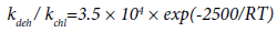 (26)
(26)
With an increase in temperature, the rate of the reaction of EDC dehydrochlorination increases faster than the rate of the chlorine conversion. At 573 K,  orders of magnitude, at
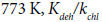 ~ 3 orders of magnitude. However, the rate of chlorine conversion also increases with increasing of temperature, which can adversely affect the selectivity of the process.
Detailed experimental data on the correlation of the rates of the reactions of EDC pyrolysis and its chlorination in the presence of small additions of chlorine, as well as of chlorine in a mixture with nitrogen oxide, were obtained by Ashmore [30,31]. The authors of [30] consider three main consecutive stages that occur when the process is initiated by small additions of chlorine:
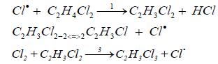
It is shown that the initial rates of formation of both VCM and 1,1,2-trichloroethane decrease with operating time of the reactor increasing; the ratio k2/k3 remains constant at a constant partial pressure of EDC. The ratio increases with increasing of the partial pressure of EDC. Adding VCM to the system reduces the rate of its formation due to shifting of the equilibrium of the reactions to the left (2,-2). The authors of [30] confirm half the order with respect to chlorine by analogy [16] and indicate that the order with respect to chlorine increases up to 0.62 as the operating time of the reactor increases. In [31] the authors provide the developed by them model of transformations of the radical C2H3Cl2 according to the reactions (2,3) on the basis of the kinetic measurements. It is shown, in particular, that the activation energy of the reaction (2) is E2=84 kJ/mol, and the pre-exponential factor is 1014 sec-1.
Based on the data of [30,31], the authors of [26] also proposed a model for the pyrolysis of EDC upon initiation with chlorine. The model includes homogeneous and heterogeneous initiation, the chain propagation in the volume and the termination at the reactor walls. The addition of chlorine to the system increases the rate of the process due to the reaction:
Cl2 +S⇔Cl +ClS
which occurs much faster compared with both homogeneous and heterogeneous decomposition of EDC directly.
Initiation of the process of EDC pyrolysis can also be carried out using perchlorosubstituted saturated hydrocarbons C1 and C2: carbon tetrachloride and hexachloroethane, as initiators. At temperatures above 400°C hexachloroethane is able to decompose according to the scheme:
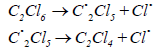
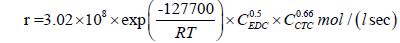
According to [10], the kinetic equation of the reaction of EDC dehydrochlorination, initiated by hexachloroethane, has the form:
 (27)
(27)
Chiltz et al. [32] estimated by calculation that the activation energy of this reaction should be ~ 167 kJ/mol. According to Semenov et al. [24,33] as well as, the difference is explained by the catalytic effect of the carbonized reactor wall. In the pyrolysis of hydrocarbons and their derivatives, in the carbon deposition on the walls of the reactor free radicals exist, the concentration of which achieves 1015 spin per gram of the deposit [33]. The presence of these radicals facilitates the decomposition of the hexachloroethane molecule into perchlorethylene and two chlorine atoms.
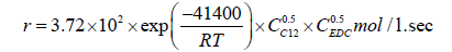
For the pyrolysis of EDC initiated by carbon tetrachloride, the kinetic equation (28) is valid [34]:
 (28)
(28)
It was shown in [33] that at 700 K (427°C) introduction of carbon tetrachloride in a concentration up to 1200 ppm into the system promotes an increase in the conversion of EDC by 13%, from 52.4 to 65.4%. This is accompanied, however, by the requirement for an additional (by ~20%) heat input. The authors of [35] note that the obtained by them calculated dependences of the conversion of EDC, the distribution of temperatures along the length of the reactor, the formation of by-products, in particular, acetylene, are in satisfactory agreement with the results of operation of industrial pyrolysis furnaces. This relies on a numerical analysis of 108 possible reactions that occur during the pyrolysis of EDC. In [35] these reactions are divided into initiation reactions, hydrogen abstraction reaction, chlorine abstraction reactions, condensation and decomposition radical reactions, molecular reactions and chain termination reactions. For each reaction, the values of the frequency factor and activation energy are given. On the basis of the analysis of these values, the authors conclude the most probable paths for the pyrolysis process of EDC.
The authors of [36-39] show that the initiating effect of a mixture of hexachloroethane and carbon tetrachloride on the pyrolysis of EDC is stronger than that of its most active component, hexachloroethane. With an increase in temperature, the initiating action of both the mixture and each component separately increases. The dependence of the conversion of EDC on the composition of the mixture has an extreme character at different temperatures. It should be noted that the maximum corresponds to a mixture containing 75% of hexachloroethane. The author of [34] points out that the synergistic effect is achieved due to the additional formation of hexachloroethane, one of the products formed as a result of decomposition of carbon tetrachloride. Hexachloroethane, in turn, decomposing at a lower temperature than carbon tetrachloride, initiates the decomposition of the latter at the same temperature. The authors of [37,39] carried out a regression analysis of the effect of various factors on the conversion of EDC in the temperature range of 460-540°C and indicated that the higher initiating activity of hexachloroethane in comparison with carbon tetrachloride is only manifested at temperatures exceeding 500°C. This fact contradicts the assumption proposed in [34], which supposes the higher initiating activity of hexachloroethane at relatively low temperatures.
The use of hexachloroethane as an initiator with a concentration of up to 1% by weight leads to an increase in the EDC conversion by 3-4% accompanied with a simultaneous decrease in the yield of by-product acetylene (by 1.2 times) and 1,3-butadiene (by a factor of 2) [40]. In our opinion, the combination of the increase in the EDC conversion with the decrease in the yield of basic impurity compounds raises certain doubts.
The authors of [40-42] proposed to use oxygen-containing compounds as initiators of the EDC pyrolysis. According to [41], chloral or chloral hydrate is an effective initiator of this process. The authors point out that at the concentration of chloral (chloral hydrate) at the level of 200-500 ppm wt. in EDC fed to pyrolysis, the yield of VCM increases, on average, by 10%. At the same time, the formation of byproduct monovinyl acetylene, as well as coke deposits, is significantly reduced. The mechanism of initiation is not considered in [41].
Similarly, the possibility of initiating the EDC pyrolysis by adding small amounts of hexachloroacetone was demonstrated in [42]. At temperatures of 460 and 500°C, the initiating action of 300 ppm hexachloroacetone is comparable to the initiating action of 100 ppm chlorine. The yield of VCM increases by 8-10% compared to the purely thermal process of EDC pyrolysis. The authors of [42] also point out an increase in the formation of by-products: acetylene, chloroprene and butadiene. The total amount of coke deposits increases slightly, but on the basis of the VCM formed it decreases by 1.2-2.5 times.
In the HOECHST AG-owned US patent [40], it was proposed to carry out the EDC pyrolysis in the presence of trichloroacetyl chloride, thionyl chloride, nitrosyl chloride. These compounds are strong initiators of the process, and their initiating capability is 3-4 times higher than the initiating capacity of chlorine. Unfortunately, the authors of [40] do not consider the possibility of water formation during the process, the presence of which in the system is usually strictly limited.
According to the data given in the HOECHST-owned patent [43], the presence of benzotrichloride in the raw EDC tends in a significant increase in the conversion of EDC. So, if for the pyrolysis of pure EDC at 490°C, conversion of the latter is 51.8%, the addition of benzotrichloride in a concentration of 250-1000 ppm promotes an increase in conversion to 76-85%. The yield of by-products is not reported. The reasons for such a pronounced initiating capability of benzotrichloride are also not discussed.
According to [38,39], the initiation of the pyrolysis process can be realized by adding hydrogen chloride to the being pyrolyzed EDC. The authors of [44] point out that in the temperature range of 450-490°C, the pyrolysis of EDC in the presence of hydrogen chloride, taken in a molar ratio to EDC equal to 0.1-1.8, proceeds with EDC conversion at the level of 95%; the main by-products are acetylene, ethylene, chloroprene, chloroform. The authors separately emphasize that the presence of hydrogen chloride in the system almost totally eliminates the formation of solid deposits on the walls of the reactor.
It was shown in [45] that the pyrolysis of EDC at 480-485°C, carried out at HCl concentration at the inlet to the reactor of up to 9,000 ppm (0.9%), promotes an increase in the EDC conversion from 33 to 49% with simultaneous reducing of the formation of impurities, such as 1,1,2-trichloroethane, trichlorethylene, perchlorethylene, and slight increasing of the yield of chloroprene. There are no indications of any change in the yield of acetylene and ethylene in [45]. The authors believe that a decrease in the formation of by-products with simultaneous increase in the conversion of EDC is due to the fact that during the EDC pyrolysis an additional chlorine atom is formed from the hydrogen chloride at the stage of nucleation of the free-radical chain process; and the chloroethyl radical, as the source of the formation of additional by-products, disappears according to the reactions:
Such an approach seems doubtful to us, first, because, according to [45], the content of ethyl chloride in the products of the process remains practically unchanged, and, second, the hypothetical reaction of hydrogen chloride with the chloroethyl radical is unlikely to occur under the conditions of the EDC pyrolysis due to a high H-Cl bond breakdown energy of 430 kJ/mol.
In general, the positive effect declared in [44,45] achieved when initiating the EDC pyrolysis by hydrogen chloride, needs, on our opinion, additional confirmation.
A strong initiating effect on the EDC pyrolysis is also provided by oxygen. The accelerating effect of oxygen upon the reaction of dehydrochlorination of chloroethanes was noted for the first time by Barton [46] and developed by him later [11]. Barton showed that the initiating activity of oxygen in the reaction of EDC dehydrochlorination is only slightly inferior to that of chlorine. According to Barton, the initiating action of oxygen is manifested in the reactions proceeding according to the radical-chain mechanism and is absent in the reactions proceeding according to the molecular mechanism (for example, for the reactions of dehydrochlorination of ethyl chloride, 1,1-dichloroethane, pentachloroethane).
The effect of oxygen on the kinetics of the radical-chain processes on the example of the EDC dehydrochlorination was studied in [47]. The reaction rate is described by the kinetic equation:
 (29)
(29)
The authors supposed that in the reaction of EDC dehydrochlorination, the accelerating effect of oxygen is due to its adsorption on the active sites of the wall. The decomposition of EDC proceeds according to the well-known mechanism with a crosstermination of the chain. Probably, the process of chain termination is preceded by the adsorption of radicals on the wall (S):

Oxygen, when being adsorbed on the wall, thereby reduces the area of active surface (S) and, consequently, leads to a decrease in the rate of chain termination, increase in chain length and rate of the process as a whole. The fractional order with respect to oxygen indicates that its adsorption proceeds in accordance with the Langmuir equation. The observed activation energy, calculated as the difference in the activation energy of the oxygen-free process (154,100 J/mol) and doubled the heat of adsorption of oxygen on the wall surface (2 × 54,300 J/mol), is 45,400 J/mol and is close to the experimental one.
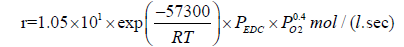
According to the data obtained in [34,48], the effect of oxygen on the process of EDC dehydrochlorination is rather complex. In the temperature range of 370-400°C, the dependence of the EDC conversion on the amount of added oxygen reaches its peak value, which shifts as the temperature rises towards a larger amount of oxygen fed. In the range, where the amount of oxygen does not exceed 1.5- 1.8% wt., it accelerates the reaction of EDC pyrolysis; in the range, where the amount of oxygen is more than 2% wt., it manifests itself as an inhibitor. The kinetic equations for each of the cases considered are as follows:
For initiation:
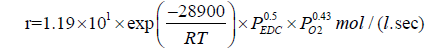 (30)
(30)
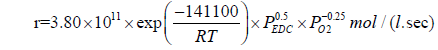 (31)
(31)
The rate of the radical-chain process can be written in the general form by the expression:
r=ri•l (32)
where r is the reaction rate, ri is the initiation rate, l is the chain length.
Thus, the reaction rate can be increased by either the initiation rate or the chain length. All the traditional initiators (chlorine, carbon tetrachloride, hexachloroethane) accelerate the process specifically by increasing the rate of initiation. Oxygen is, apparently, the only initiator that promotes an increase in the length of the chain [48]. Oxygen, adsorbed on the active sites of carbon deposits, blocks these centers and, thereby, prevents chain termination.
The author of [48] points out that, according to the assumption of the accelerating effect of oxygen on this process, the concentration of active sites should be proportional to the total surface area of the carbon deposit and inversely proportional to the concentration of adsorbed oxygen:
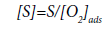 (33)
(33)
In turn, the concentration of oxygen adsorbed on the surface of the carbon deposit in accordance with the Langmuir equation is:
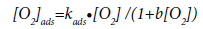 (34)
(34)
where kads is the adsorption constant of oxygen on the surface of pyrolytic carbon, b is the adsorption coefficient, and [O2] is the oxygen concentration in the reactor.
Taking into account Eqs. (33) and (34), the total rate of the EDC dehydrochlorination in the presence of oxygen is:
 (35)
(35)
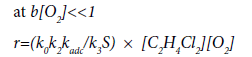 (36)
(36)
where k0, k2, k3 are the rate constants of the initiation, chain propagation and linear termination stages, respectively.
In favor of the proposed reaction mechanism is the fact that the initiating action of oxygen is only manifested, when the walls of the reactor are covered by pyrolytic carbon. The author of [48] confirms this by observing that the conversion of EDC in thermal and oxygeninitiated processes in non-carbonized reactors coincides within the first five minutes. It is during this period of time that pyrolytic carbon deposition on the walls of the reactor occurs [49].
The effect of oxygen additions on the kinetics of the EDC pyrolysis under adiabatic compression (under strictly homogeneous conditions) was studied in [50]. The authors pointed out that, by analogy with purely thermal pyrolysis, the process of EDC dehydrochlorination proceeds only through a monomolecular mechanism. It should be noted that the increase in the EDC conversion at high compression ratios is due to the reactions of homogeneous deep oxidation of EDC, and, to a greater extent, that of VCM. Homogeneous radical-chain reactions of oxidative dehydrogenation and dehydrochlorination do not make a significant contribution to the overall process. In [50] a hypothesis was also made on the causes of acceleration and inhibition of the process with a change in the oxygen concentration. The acceleration of the process under heterogeneous conditions may depend on the temperature increasing in the near-wall zone due to heat emission in the oxidation reactions. The authors attribute the inhibition of the process to the strong adsorption of water formed in the oxidation reactions. We have not found evidences of this assumption in literary.
According to [51], the process of EDC pyrolysis should be carried out in conditions of almost complete absence of oxygen (the content of the latter should not exceed 0.5-2.0 ppm). This is due to the fact that presence of oxygen in being pyrolyzed EDC in a concentration of 40- 200 ppm contributes to a drastic increase in the yield of by-products and coke. At the same time, the author of [51] points to an increase in the corrosion of the reactor walls. Quantitative estimates of the phenomena of coke formation and corrosion are not given; however, it is indicated that a decrease in the oxygen concentration from 43 to 0.5-2.0 ppm reduces the rate of coke formation by 22%. The last thesis raises some doubts, as the presence of oxygen in the system under the conditions of the EDC pyrolysis should contribute to the partial “burning out” of carbon deposits on the reactor walls.
Initiation of the process of EDC pyrolysis can also be carried out by exposure to external radiation sources. It was shown in [52] that in the presence of laser radiation with a power of 5 W/cm2, the EDC pyrolysis can be carried out at temperatures of 300-350°C, while achieving the EDC conversion that of the level of thermal pyrolysis at 500°C. An increase in the rate of chain initiation due to photodissociation of EDC with the formation of a chlorine radical was estimated. According to [52], the rate of “laser production” of chlorine radicals is 1014 particles/ cm3 sec, which is four orders of magnitude higher than the rate of the chlorine radicals’ formation at 700 K during thermal pyrolysis. This means that the upper limit of the laser acceleration of the chain reaction due to light absorption by the EDC molecules is approximately 102 ((104)0.5). The authors point out that as the temperature decreases, the magnitude of the acceleration should increase drastically, and as it increases should fall.
The authors of [53] point out that when initiating the process of EDC pyrolysis by a laser with a wavelength of 308 nm, the primary decomposition product is a dichloroethyl radical. Further conversion of the dichloroethyl radical is energetically most advantageous, when VCM molecule and the chlorine radical are formed. Theoretical calculations in [53] showed that under these conditions the target VCM is formed with high selectivity.
In [54], the effect of O2/Ar plasma on EDC is considered. Under the conditions of the process, EDC decomposes virtually completely (90- 99%) with the formation of a wide range of products, the main of which are hydrogen chloride, carbon oxide and dioxide. The formation of a wide range of chlorinated hydrocarbons, as well as phosgene, acetylene, ethylene, ethane was also observed. Obviously that this system cannot be used for practical purposes, associated with the production of VCM.
A number of organochlorine compounds are the inhibitors of the process of EDC pyrolysis [37-39]. These include allyl chloride, 1,2-dichloropropane, chloroprene, 1,1-dichloroethane, 1,2-dichloroethylenes, vinylidene chloride. Thus, the presence in the raw EDC of 0.5% wt. 1,2-dichloropropane, 1,2,3-trichloropropane or allyl chloride reduces the degree of conversion of the latter by a factor of 1.5-3. The effect of these compounds on the EDC pyrolysis is due to the fact that they give more stable radicals than EDC. In allyl chloride, the formation of a stable radical takes place by the addition of a chlorine radical, which requires much less energy than the formation of stable radicals from chloropropanes by breakdown of the C-H bond. In this case, the same stable CH2Cl-CHCl-C•H2 radical can form from 1,2-dichloropropane and allyl chloride. However, allyl chloride is a stronger inhibitor specifically because of its greater reactivity when forming a stable radical.
The quantitative characteristics of the process of EDC pyrolysis both in the purely thermal mode and under the conditions of the addition of carbon tetrachloride and chlorine as initiators to the system were considered [49]. A detailed analysis of the impurities formed as a function of the initiator concentration is given. It is shown that at 500°C the most noticeable impurities are acetylene, vinylidene chloride and chloroprene. It is pointed out as well that, at lower temperatures (350 and 400°C), the primary product of the EDC conversion is ethylene, which further undergoes secondary transformations. When the process is initiated with chlorine and carbon tetrachloride with a content of the latter of up to 1300 ppm, the acetylene concentration in the process products increases by a factor of 1.5-1.6, that of chloroprene- in 1.5 (CCl4)- 2.6 (Cl2) times. The content of benzene and trichlorethylene in the process products remains virtually unchanged.
The authors of [35] showed that when initiating the process of EDC pyrolysis by carbon tetrachloride at a concentration of up to 1200 ppm (mol), the acetylene concentration in the reaction gas increases from 300 to 430 ppm (mol). It is indicated that acetylene is a product of possible conversions, both directly of VCM molecule and of C2H3Cl, C2H2Cl, C2H3, CH2Cl and Cl radicals. The increase in the acetylene yield correlates with an increase in the EDC conversion, which is achieved both with increasing in temperature and with the presence of an initiator. It is also indicated [35] that acetylene is a compound, from which coke can be further formed under the conditions of the process.
In [55] the kinetic analysis of the main reaction and a number of by-reactions during the thermal pyrolysis of EDC was carried out. It is shown that an increase in the temperature of the process, as well as the residence time, most significantly affect the increase in the conversion of EDC. An increase in pressure from 1.0 to 1.4 MPa also increases the conversion of EDC, albeit to a much lesser degree. An increase in the residence time of the reaction mixture in the reactor promotes a drastic (by a factor of 1.5-2) increase in the yield of acetylene and 1,1-dichloroethane as well. The yield of ethylene increases insignificantly. The author [55] believes that ethylene is formed via an intermediate chloroethyl radical.
In a number of works the selectivity issues are considered in the context of the influence of impurities most commonly contained in EDC fed in the industrial pyrolysis furnaces. Typically, the quality of EDC, fed to pyrolysis in industrial conditions, is 99.7-99.8%. As impurities it can contain ethylene, as well as other organic compounds, the complete separation of which from the raw EDC is restricted due to the close boiling points. These include, in particular, benzene (Tboil=80.1°C) and trichlorethylene (Tboil=86.7°C). The boiling point of EDC is 83.47°C. EDC also usually contains a small amount of water.
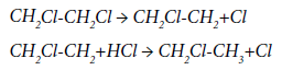
Ethylene markedly inhibits the reaction of EDC pyrolysis; this effect is most noticeable for ethylene concentrations in the range of 0.1-1% [56]. Further increasing of the ethylene content in the reaction mixture has virtually no effect on the rate of the pyrolysis process. The order of the reaction with respect to ethylene in the area of strong inhibition is -1, the activation energy is 79.6 kJ/mol. The authors of [57] believe that the reason for the inhibition is the interaction of a Cl radical with an ethylene molecule and the formation of an inactive vinyl radical and an HCl molecule.
An analysis of the change in the selectivity of the EDC pyrolysis in the presence of ethylene, carried out in [57], showed that the introduction of 0.1% ethylene into the system promotes an increase in butadiene content in pyrolysis products from 40 to 110 ppm. It should be noted that an increase in the ethylene content above 0.3% contributes to an exponential increase in the rate of butadiene formation. The authors of [57] believe that butadiene is formed by dimerization of the vinyl radical, which, in turn, is formed, when the vinyl chloride decomposes according to the total reaction:
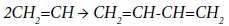
Under normal conditions of thermal pyrolysis, the formation of the vinyl radical proceeds at a low rate, and the concentration of the CH2=CH radical is small; therefore, butadiene is formed in small amounts. Ethylene introduced into the system can easy, virtually without an energy barrier (Eakt ~ 8 kJ/ol), interact with the chlorine atom, forming the radical responsible for the formation of butadiene. Such mechanism excludes the effect of ethylene on the formation of other impurities, which was confirmed experimentally in [57].
In this connection, the method proposed in [58] for carrying out the pyrolysis of EDC in the presence of ethylene in an amount of 0.02-0.1 mole per mole of EDC is of great doubt. The process indicators obtained by the authors, the EDC conversion of 66% at 390-420°C, indicate that the initiating effect of ethylene should be virtually at the chlorine level, which is not confirmed neither by the results of other researchers, nor by the experience of industrial use of the process.
The authors of [59] studied the effect of moisture additives on the pyrolysis of EDC. It is shown that in the range of water concentrations in the raw EDC of 25-1475 ppm, the rate of dehydrochlorination is independent of its content in the raw product. Water also has no effect on the yield of low-boiling by-products, such as ethylene, acetylene, methyl chloride, butadiene, etc. In contrast to this, the selectivity of the formation of certain high-boiling impurities varies: for example, the content of perchlorethylene and 1,1-dichloroethane in the process products reduces by 3-5 times, and that of vinylidene chloride and chloroform increases by 1.5-2 times. No mechanism of this effect is given by the authors of [59].
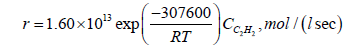
The conformities in the formation of by-products and coke during the thermal pyrolysis of EDC were studied in [27,60,61]. The authors of [27] when studying the process of EDC pyrolysis in a quartz reactor showed that the share of by-product acetylene and chloroprene is 70-80% in the total balance of the by-products formed. Acetylene is formed due to a partial decomposition of vinyl chloride according to the reaction:
The rate of acetylene formation is described in [27] by the first order equation:
 (37)
(37)
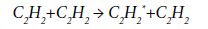
Most likely, chloroprene is the product of the interaction of vinyl chloride with acetylene:
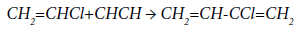
The kinetic equation of the reaction of chloroprene formation is:
 (38)
(38)
Thus, the rate of formation of acetylene and chloroprene is a function of VCM concentration, so an increase in the EDC conversion with a corresponding increase in the concentration of VCM inevitably leads to an increase in the concentration of these by-products. The obtained results show that an increase in the EDC conversion due to a change in the main process parameters (increase in temperature, residence time of EDC, surface of the reaction zone, or initiation of the process) leads to a decrease in the selectivity of the formation of the desired product, VCM. The experimental data given in [27] confirm this conclusion: in the temperature range of 460-500°C the increase in the conversion of EDC from 24.5 to 45% leads to a decrease in the selectivity of VCM production from 99.6 to 98.4%. Simultaneously, the selectivity of acetylene formation increases from 0.15 to 0.68% and that of chloroprene increases from 0.1 to 0.6%.
In [60], the effect of metals on the EDC pyrolysis indicators was studied. It is established that the introduction of metal plates made of heat-resistant steel ХН78Т (analog of N06025, hereinafter referred to as “N06025” for clarity) (content of nickel 70-81%, of chromium 19-22%) and stainless steel 12Х18Н10Т (analog of AISI 321, hereinafter referred to as “321 SS” for clarity) (content of nickel 9-11%, of chromium 17- 19%), significantly changes the process indicators in comparison with the system containing only quartz elements in it. In particular, the conversion of EDC increases by 10-15%, and this is accompanied by a drastic (from 99 to 96.5-97%) decrease in the selectivity of VCM formation. The selectivity of acetylene and chloroprene formation increases from 0.5 to 1.2-1.7%. There was also a significant increase in the selectivity of the ethylene formation due to the reaction of EDC dechlorination - up to 0.2-0.3%. As far as the surface is being coked, the selectivity of ethylene formation is somewhat reduced. The steel 321 SS is more active with respect to by-reactions compared to the N06025 steel.
The authors of [61] considered the effect of additions of trichlorethylene and benzene on the indicators of EDC pyrolysis. It was shown that trichlorethylene is a weak initiator of the process. The increase in its share in the being pyrolyzed EDC to 0.8% leads to an increase in the EDC conversion by 4-5%, while decreasing the selectivity of VCM formation by 0.7-1% due, first of all, to the corresponding increase in the share of by-reactions of acetylene and chloroprene formation. The activation energy of the process initiated by trichlorethylene is equal to 128,300 J/mol.
In accordance with [61], the presence of benzene in the concentration range of (0.1-0.8)% in the system exerts virtually no effect on the EDC conversion rates, the selectivity of VCM formation and the by-product acetylene and chloroprene. Benzene fed to pyrolysis with EDC, converts to (13-16)%. The products of its conversion are the chlorine derivatives of benzene.
These results differ from the data of [34], according to which benzene at low concentrations (up to 0.2%) is an inhibitor of the process; at the same time a further increase in the benzene concentration to 0.5% leads to some increase in the EDC conversion, which, however, does not reach the values obtained in the thermal pyrolysis. The author [34] points out that since benzene has a significant reactivity, its introduction in small amounts leads to the binding of Cl. radicals, contributing to inhibition of the process.
Another by-product that is always formed during the EDC pyrolysis is methyl chloride. According to [48], the selectivity of its formation also increases (from 20 to 100 ppm) with an increase in the EDC conversion from 20 to 70%.
The influence of hydrogen on the EDC pyrolysis was considered in [62,63]. The authors showed [62] that hydrogen has a noticeable inhibitory effect, with the maximum inhibitory effect being achieved at 430-480°C and hydrogen concentration of 2-3%. The kinetic equation (39) is given:
 (39)
(39)
The authors believe that the inhibition of the reaction is primarily due to the fact that the presence of hydrogen promotes chain termination with the formation of atomic hydrogen, which does not participate in the propagation of the reaction chain. The authors of [62] believe that a reduction in the formation of carbon deposits is due specifically to the effect of inhibition, however, they do not preset any experimental confirmation of this thesis.
The decrease in the selectivity of the formation of by-products in the presence of hydrogen in the system is pointed out in [63]. With an increase in the hydrogen concentration in the reaction gases up to 0.3%, the content of acetylene in the pyrolysis products falls from 0.39 to 0.06%. The effect of hydrogen concentration on the methyl chloride content is relatively small (yield of the latter increases from 0.2 to 0.4%). Dependence of butadiene content on hydrogen concentration is extremal. The maximum amount of butadiene (0.11%) is observed with the addition of 0.2% hydrogen. An increase in the hydrogen concentration to 0.55% leads to an increase in the ethylene content from 0.14 to 5.7%. A further increase in the hydrogen concentration to 1.2% leads to a slight decrease in the ethylene content. In addition, it was shown that an increase in the concentration of hydrogen in the reaction mixture causes a gradual decrease in the content of chloroprene, chloroform, chlorobenzene and their subsequent disappearance, as well as an increase in the yield of propane, propylene and isobutylene [63].
According to [64], the pyrolysis of EDC with the hydrogen concentration of 0.2-1.0% mol. leads to a decrease in the selectivity of the formation of chloroprene by 25-45%, the selectivity of acetylene formation decreases negligible with that. The positive effect, according to [64], is also that the hydrogen concentration based on the EDC fed at the level not exceeding 1% mol. has no effect on the EDC conversion, which, as the temperature changes from 460 to 480°C, increases from 40 to 58%.
The conformities of the thermal decomposition of acetylene at 400-1500 K are considered in [65]. The first stage is the excitation of acetylene molecule according to the reaction:
Further, the reaction of dimerization proceeds to form an excited vinylacetylene molecule:
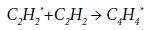
and then:
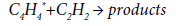
It is assumed that the activation energy of the reaction of primary excitation of acetylene molecule is in the range of 230-251 kJ/mol. These values are too large for realization of this scheme under the conditions of EDC pyrolysis. For this reason, the formation of a spectrum of byproducts in the pyrolysis process, obviously, proceeds along other paths, including the reactions of acetylene trimerization or its condensation, both with the target VCM and with other by-products.
The formation of solid carbon deposits, the so-called “coke”, during the EDC pyrolysis is one of the most important operational characteristics of the process. The relative amount of coke produced in the industrial furnaces on the base of the reacted EDC is small and is amounted to hundredths of a percent. However, all companies that produce VCM give top priority to this indicator.
The main problems emerging in the use of industrial furnaces for EDC pyrolysis while the coke deposition increases, can be divided into three groups. First, a coke layer on the coil walls leads to a decrease in the heat transfer factor, which requires an increase in the temperature of fuel burning to achieve the required conversion of dichloroethane. Second, the coke layer gradually reduces the cross-section of the pipes, which leads to an increase in the pressure drop and, eventually, to the furnace shutdown for regeneration. Third, the coke particles contained in the gas stream must be removed from the liquid after the quench column in order to avoid contamination of other process units [66].
In general case, Bukharkin [67] represents the overall process of carbonaceous products formation in the vapor phase, typical of the thermal pyrolysis of hydrocarbons in industrial conditions as including the following stages:
- decomposition of hydrocarbons in the gas phase, accumulation of unsaturated and aromatic compounds, their condensation and/or polymerization;
- formation of polyacetylenes and analogous compounds with subsequent ring closure;
- growth of carbon particles (nuclei) and decomposition of hydrocarbons on the surface of these nuclei;
- agglomeration of the formed nuclei and their deactivation; formation of the wall “coke” deposit.
It was pointed out in [68] that benzene promotes the formation of “nuclei” during pyrolysis, and in the formation of the latter the following substances involve with different rates and activities:
Allen → 1,3-Butadiene → Acetylene
Compounds in which the vinyl group is coupled to an electron withdrawing group (for example, vinyl acetylene) form dimers and polymers at temperatures of the order of 573-773 K, which are then converted to polycyclic aromatic hydrocarbons and coke deposits [69].
Albright et al. [70] stated the general principles of coke formation in the form of three parallel mechanisms using the ethylene formation process by raw petroleum pyrolysis as an example:
Filamentous coke, which formation is catalyzed by metals. Intermediates are metal hydrides. The filamentous coke exists in the form of needles or fibers. Carbon filaments are formed on catalytically active areas of the surface containing metal atoms of the iron group. The length of such carbon filaments is several orders of magnitude greater than their diameter.
Pyrocarbon is formed from polynuclear aromatic viscous droplets, which convert themselves into coke when contacting with a hot surface, whereas the coke morphology is dependent on the viscosity of the droplets.
The reaction of olefin, diene, acetylene compounds, as well as free radicals with free radicals on the coked surface. The coke layer formed according to the mechanisms 1 and 2 grows through the mechanism 3.
The authors of [70] also point out that these principles are valid for the process of EDC pyrolysis as well.
Catalytic coke formed from hydrocarbons on the metal surfaces has a fibrous structure; intermediates in its formation are metal carbides [71]. Catalytic coke provides higher density than that of non-catalytic one formed by tar droplet formation.
The authors of [72] investigated the influence of various factors on the formation of coke during the EDC pyrolysis in a laboratory quartz reactor. It is shown that the formation of coke changes simbatically with the EDC conversion and depends on a number of factors, one of which is the EDC composition at the reactor inlet. At the same time, the introduction of carbon tetrachloride into the system indirectly, through an increase in the EDC conversion, promotes the increasing of coke formation. The authors of [72] also showed that the main precursor of coke is chloroprene. Using 14C-labeled isotopes, it was shown that 50- 60% of the carbon contained in chloroprene is converted into coke. The presence in the system of benzene, as well as acetylene, has practically no effect on the formation of coke.
Borsa et al. [66] points out that two different types of coke are deposited on the walls of the reactor: “Hard” coke is formed in the hot zone of the reactor and soft coke is formed in the colder zone at the exit of the reactor. According to [63], hard coke is similar to pyrolytic graphite in structure. Borsa also points out that the tar droplets, which are mainly fragments of C4 hydrocarbons, are formed in the gas phase. Then they impinge on the surface where they undergo dehydrogenation and dechlorination, and coalesce to form coke [73].
Detailed studies of the quantitative characteristics of coke formation, as well as the structure of coke deposits, were carried out [27]. The authors confirm that chloroprene is the main precursor of coke [72]. It is shown that a decrease in the selectivity of VCM formation from 99.6 to 98.4% due to an increase in the yield of the byproduct acetylene and chloroprene is accompanied by a drastic (by 4-6 times) increase in coke deposits on the walls of the reactor.
To assess the intensity of coke formation, Borsa et al. introduced the concept of “coke index” [66]. The coke index (I) is the ratio per unit area of the coke weight deposited on the surface to the reacted EDC weight. According to [66], under the conditions of a laboratory quartz reactor with the conversion of EDC at the level of 50-55%, the value of I is (7.5-11) × 10-8 1/cm2. These data agree with [27], according to which the value of I for the reaction zone and the exit zone is equal to (7.2- 7.7) × 10-8 1/cm2. The overheating zone is characterized by a lower coke formation intensity: I=3.9 × 10⁻⁸ 1/cm2.
The data of physical and chemical studies of coke carried out, among other, with the help of a scanning electron microscope, allows suggesting the following mechanism for the coke deposits formation [27]. At the initial stage of the EDC thermal destruction, the difference in the composition of the intermediate compounds containing in the reaction mixture in the form of the gas phase is assumed. The authors of [27] confirmed this assumption by the different composition of coke deposited in the overheating zone. At low temperatures (350-390°C), the most probable is the decomposition of EDC with the formation of chlorinated ethane and ethylene, which contribute to the production of low-temperature pyrolytic carbon. Building-up of the pyrolytic carbon leads to the formation of the so-called “column structure”.
The formation of pyrolytic carbon on a solid surface occurs simultaneously with the formation of dense anisotropic coke, which is a spherical agglomerate of 70-200 nm in diameter. These reactions proceed in parallel and are competing.
Another type of deposit is a turbostatic carbon with particle size of 1.3-1.5 μm formed by the products of polymerization and polycondensation of aromatic hydrocarbons. In total, the authors of [27] point out to three types of coke deposits: pyrocarbon, anisotropic coke, and turbostatic carbon formed by the products of polymerization and polycondensation of aromatic hydrocarbons.
For a more accurate quantitative assessment of the process of coke formation occurring in industrial furnaces for EDC pyrolysis, a number of authors have studied the influence of metals on the intensity of coke formation and its structure [60,66,73-75]. According to [74], the coke deposits on the stainless-steel elements in the reactor are significantly higher than that on quartz or ceramic elements. The process of coke deposition on the metal surface is accompanied by the formation of FeCl2, which in turn is a catalyst for the formation of coke.
The catalytic effect of iron dichloride on the formation of coke was confirmed in [66]; however, it was concluded that the nature of the metal (Cr, Ni, Fe, stainless steel) does not fundamentally affect the character of the coke formed: hard or soft coke. In all cases, the presence of metal in the system under 480°C leads to an increase in the EDC conversion from 43 to 61% and an increase in the intensity of coke formation. The increase in the metal surface also promotes an increase in the EDC conversion and in the associated amount of coke produced. Analyzes of metal plates subjected to coke deposition point out, as well as in [72], the presence of FeCl2 on the metal surface.
According to [75], iron and iron oxide can form an active surface for carbon deposits, since iron oxide reacts readily with chlorohydrocarbons to form iron (II) chloride. The surface of iron chloride initiates a radicalchain reaction according to the oxidation-reduction mechanism and accelerates the polymerization of chloroolefins. It was suggested [75] that hydrogen chloride released during the thermal decomposition of EDC, as well as other impurity chlorinated hydrocarbons, can cause surface corrosion with the formation of iron chloride accelerating the formation of carbon deposits.
A series of experiments was carried out in [60] to determine the quantitative characteristics of the formation of carbon deposits when inserting plates made of N06025 and 321 SS steels into the laboratory quartz reactor (for the content of metals in these steels, see the section “The issues of the selectivity of EDC pyrolysis”). The presence of metal plates in the system contributes, along with an increase in the conversion of EDC and a decrease in the selectivity of the VCM formation, a drastic increase in the intensity of the formation of carbon deposits. The authors pointed out that the most intensive deposition of coke occurs on the elements with a high nickel content (N06025 steel, containing up to 80% of Ni). The coke index in the reaction zone is 1.4 × 10⁻⁴ 1/cm2, i.e., it by more than three orders of magnitude exceeds the corresponding value for the quartz surface.
The steel 321 SS is less active in the process of coke formation: the coke index in the reaction zone is 9.7 × 10⁻⁶ 1/cm2, which is 15-16 times lower in comparison with the N06025 steel, although it exceeds the corresponding value for the quartz surface by 1.5-2 orders of magnitude.
According to [60], the antibate selectivity of chloroprene formation and of the coke index for the N06025 and 321 SS steels takes place. Although the selectivity of chloroprene formation on N06025 steel is ~1.5 times lower in comparison with that of 321 SS, the coke index for N06025 exceeds the corresponding value for 321 SS by an order of magnitude. Based on this, the authors conclude that nickel is a more effective catalyst for the formation of coke deposits from chloroprene. By estimations, on the N06025 plates up to 25% of chloroprene formed during pyrolysis is further converted into coke; the corresponding value for 321 SS steel is 2.5-3%.
Studies of the structure of carbon deposits formed showed [60] that the coke is not completely carbonized, 35-45% of carbon atoms are bonded to hydrogen. This indicates a decrease in the share of dehydrogenation reactions compared to the quartz surface. It is also shown that metals migrate from the surface of the plates to coke deposits, and the rate of iron migration significantly exceeds the rate of migration of nickel and chromium. The chromium content in the coke deposits is two orders of magnitude lower than that of iron and nickel. The authors also showed that polycondensation occurs on the surface of metal plates during the adsorption of chloroprene, whereas each cluster of coke is formed from 3-4 chloroprene molecules. When such clusters are formed, an average of 2 molecules of hydrogen chloride are released, with the transition of the latter to the gas phase.
The obtained results in general correlate with the data of [67,70,76-78], in which the effect of metals on the parameters of raw hydrocarbons processing is considered. According to [76], during the pyrolysis of petroleum raw materials the coke formation is promoted to the greatest extent by iron and nickel. By activity to coke formation, the metals are arranged in the following order:
Fe > Ni > Ti > Zr > Cu > W
Under process conditions that promote the formation of oxides on the surface, coke deposition in the pyrolysis reactor is enhanced. The materials contributing to the reduction of coke deposits include chromium oxide, and silicon, aluminum, titanium and niobium compounds [76].
Bukharkin [67] points out that by the relative activity in the reactions leading to the accumulation of compaction products in the high-temperature zone (up to 625°C) (321 SS activity is taken as 1) the metals and alloys can be arranged as follows:
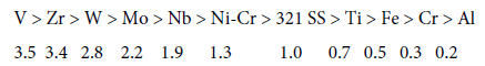
All these data indicate that nickel included in most of the heatresistant alloys contributes to an increase in the intensity of the compaction products deposition on the coil walls of the pyrolysis furnaces.
These conformities are confirmed by Albright et al. [61,70,78], who considered the formation of the compaction products in the processes of ethylene obtaining by the pyrolysis of raw petroleum. In particular, it is shown in these studies that coke contains iron, nickel and chromium, which migrate to carbon deposits from the metal surface. It should be noted that the migration of chromium is maximum from the clean walls of the reactor, then it slows down significantly. Nickel in [77] is designated as the most active catalyst in coke formation.
The foregoing points to similar conformities of coke formation in the pyrolysis of EDC and raw petroleum.
As mentioned above, the selectivity of EDC pyrolysis, as well as the intensity of the formation of carbon deposits, are a function of the EDC conversion, regardless of the reason for the change in conversion. The pyrolysis of EDC with benzene additives is subjected to a somewhat different conformities. According to [61], an increase in the mass fraction of benzene in EDC to 0.8% at 480°C leads to an increase in coke deposition in ~1.5 times in comparison with the EDC pyrolysis without benzene. As noted above, the presence of benzene in the system does not affect the EDC conversion and the selectivity of VCM and by-products formation.
Based on the data of physical and chemical studies of coke samples carried out in [61], the authors make an assumption about the coke formation pattern. Condensation of aromatic rings is accompanied with microradicals formation. Various radicals existing in the reaction mixture add themselves to carbon atoms with free valences. Consequently, each addition of benzene to the EDC pyrolysis, involving into the process unsaturated chlorinated and other hydrocarbons, such as acetylene, chloroprene, etc., leads to an increase in the formation of polycondensed organic polymers of various sizes and structures. Most of them, upon reaching the saturated vapor state, settle on a hot surface at a practically constant rate. Such assumption is confirmed by the data of the elemental composition of cokes, according to which hydrogen content in the range of (1-3)% and high chlorine content at the level of (15-23)% may point out the formation of high molecular weight aromatic condensed systems, where the lack of hydrogen atoms is compensated by chlorine atoms. Thus, the coke formed during benzene conversions within the EDC pyrolysis is obtained in parallel with the coke formed directly from EDC, VCM and products of their secondary transformations. The authors of [61] recommend carrying out the pyrolysis process in industrial conditions, using EDC with a benzene content of at most 0.1%, as these concentrations have no fundamental effect on the amount of coke formed.
According to [79], coke formation in the industrial furnaces for EDC pyrolysis significantly decreases, when alkyl- or aryl-substituted phosphines are added to the system. It is shown that during a 2-hour operation the weight of coke formed decreases by 12-20 times. The yield of VCM in the case of treated surface is stable and remains at the level of 44-45%. On an untreated surface, during 2-hour operation it falls drastically to 34-35%. The use of such an approach in the industrial conditions seems to us being promising; at the same time, it is necessary to solve the issue of possible contamination of the process products with phosphorus-containing compounds.
In relation to the coke formation, one should separately consider the EDC pyrolysis in the presence of hydrogen additives. This technique is quite common for the pyrolysis of raw petroleum. Thus, in [76,80] it is pointed out that hydrogen is an effective initiating additive to petroleum fractions at the pyrolysis of hydrocarbon feedstocks. The introduction of hydrogen into the reaction zone accelerates the primary reactions of the feedstock decomposition and the further reactions of decomposition of olefins formed in the first stage of the process (propylene, butenes) with additional formation, in particular, ethylene. At the same time, the presence of hydrogen in the system leads to a decrease in coke formation, since, by attaching to unsaturated and inactive radicals, which gradually form coke, hydrogen terminates the radical chain reactions leading to coke formation.
Hydrogen significantly inhibits the formation of pyrolytic carbon: at 900°C on a carbon surface occupied with adsorbed hydrogen, the rate of pyrocarbon formation due to decomposition of methane is (4±1) × 10-3 of the velocity on the surface free of hydrogen. The mechanism of hydrocarbons decomposition on a solid surface occupied with adsorbed hydrogen was proposed in [80]. According to it, molecules of hydrocarbon decompose to elements, when colliding with the free active sites of the surface. Some active sites are occupied by hydrogen that adsorbs on carbon much more readily than hydrocarbons. This probably helps to reduce the degree of hydrocarbons adsorption on the surface and decrease correspondingly the amount of coke formed.
The rate of pyrocarbon formation is inversely proportional to the hydrogen partial pressure to a power of 0.5. The activation energy for decomposition of a hydrocarbon molecule into elements is 42-48 kJ/ mol [68]. Such a low value of the activation energy corresponds to the fact that a molecule reacts with an active site of the carbon surface as with a free radical.
According to [67], the dissolution (occlusion) of gaseous hydrogen in the coil metal can have a significant effect on the catalytic properties of its surface. The amount of hydrogen dissolved in a structural metal or alloy depends on its chemical composition and can be found by the equation:
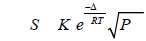 (40)
(40)
where, S, volume of hydrogen dissolved (sorbed) in the crystal lattice of the metal, cm3/100 g of metal; ΔH, heat of hydrogen dissolution in metal, J/mol; PH2- partial pressure of hydrogen in the gas phase, Pa. The values of K0 and ΔH are given in [81] and allow estimating the solubility of hydrogen in technical alloys at different pressures in the temperature range of 500-900°C.
Many doping additives in alloys: titanium, zirconium, lanthanum, cerium, etc., have an abnormally high hydrogen absorption capacity in a wide range of temperatures. The amount of hydrogen occluded in 1 g of titanium is (5-6) × 103 times greater than that in 1 g of iron or nickel.
Differences in the hydrogen solubility in metals can affect the “concentration” of active sites on the surface being in contact with hydrocarbons. Developed enough surface of the coil can lead to the fact that the coil material proves to be an active catalyst providing not only the decomposition of hydrocarbons, but also a high rate of interaction of the “coke precursors” and the hydrogen dissolved in the material. In this case, the increased partial pressure of hydrogen in the system and the presence of “hydrogenating” sites in the alloy can lead to a decrease in coke deposition.
The effect of hydrogen on coke formation directly in the EDC pyrolysis was considered in [82,83]. According to [82], the presence in a system of hydrogen in a concentration of up to 2% mol. leads to a decrease in the EDC conversion of by 3-4% compared to a purely thermal process. This is accompanied by a significant (by 2-4 times) reduction in the formation of coke deposits, and this effect is most pronounced in the reaction zone and is somewhat lower in the overheating and exit zones. Decrease in the formation of coke deposits is most noticeable during the process carried out at a relatively low temperature (480°C).
The authors of [83] showed that an increase in the hydrogen concentration from 0 to 0.5% mol. leads to a decrease in the thickness of the coke layer by 1.8-2 times. At the same time, the greatest thickness of the coke layer was observed in the exit zone of the reaction product, which may be a result of coke migration along the length of the reactor. It is also shown that a further increase in the hydrogen concentration does not have a significant effect on the thickness of the layer. It was found that for large (1-2)% mol. hydrogen concentrations, the reactor walls are subject to decarbonization, i.e., the coke deposits are partially removed from the walls. At this the EDC conversion increases, which, in turn, leads to an increase in the coke formation. Thus, a cyclic process of coke formation and removal proceeds in the system with establishment of some kind of equilibrium state.
The authors of [83] explain the decrease in the intensity of coke formation during the EDC pyrolysis with hydrogen additives by a combination of two effects. The first of these is the inhibition of the process by hydrogen, which leads to a decrease in the EDC conversion and, as a consequence, to a decrease in coke formation, as a function of the EDC conversion. The second one is the proceeding of the reactions of hydrogenation of both coke itself and its precursors- acetylene and chloroprene. This is confirmed by the fact that the selectivity of the chloroprene formation in the presence of hydrogen is reduced by a factor of 1.5-2, and that of acetylene by a factor of 1.2-1.6 compared with the process of purely thermal pyrolysis of EDC.
The structure of the coke formed was also studied. It is shown that during the EDC pyrolysis with additives of 0.5% mol. of hydrogen, the coke formation pattern is similar to the process of thermal pyrolysis, but in the reaction and exit zones small formations of ribbon-shaped coke are observed, which is apparently due to the effect of iron compounds existing on the surface layer of coke.
In our opinion, the process of EDC pyrolysis with hydrogen additives has a certain prospect for implementation in industrial conditions; however, a comparative assessment should be made of the effects of increasing the selectivity of VCM formation and reducing the EDC conversion, which may be associated with an increase in energy costs.
Simulation of the process of EDC pyrolysis is a necessary condition for development and creation of industrial furnaces, in which this process is carried out. In the development of industrial process, detailed kinetic and thermodynamic analysis of the reactions taking place under process conditions, the calculations of the conditions for mass transfer and heat input, and the determination of an optimal temperature profile along the length of the reactor should be carried out. It is important to note that as the process intensifies, the amount of heat supplied should also increase. This imposes rather strict restrictions on the unit throughput of the furnaces for EDC pyrolysis.
In [84], a model of the process in an element (tube) of an industrial furnace for EDC pyrolysis is considered with the following geometric and operational characteristics: the total length- 280 m; inner diameter- 0.12 m; EDC consumption- 16000 kg/hour; inlet temperature- 200°C; outlet temperature- 500°C; outlet pressure- 1 MPa; contact time- 12-14 sec; EDC conversion- 55%. For these process conditions, the authors of [84] give the equations of material and energy balance, which are used later for computational studies. It is separately pointed out that the calculations are carried out for the conditions of both clean and coked pipe surface. During the simulation, it was shown that to achieve the target process parameters, the temperature of a clean (free of coke) pipe wall should be 150-200°C lower than that of a coked surface. The heat release decreases, as the length of the pipe increases, and this is significantly more pronounced for the contaminated surface.
An important feature of the model given in [84] is the calculated data on the rate of coke deposition. The authors point out two mechanisms of coke deposition: molecular and radical. The rate of each type of coke deposition is described by equations (41) and (42):
rmol=107.5 exp(-22500/RT) CVCM, mm/month (41)
rrad=109.0 (CRVC+bCC2H3), mm/month (42)
where b is a constant describing the lower reactivity of the vinyl radical as compared to the “vinyl chloride” (RVC) radical. The authors also point out that the thermal conductivity of the coke deposits is, on the average, 3 kcal/(m hour°C), which is lower in comparison with the corresponding value in the process of steam cracking (4-12 kcal/ (m hour°C)). According to the calculations carried out in [84], the thickness of the coke layer equal to 20 mm is formed in 9 months of operation.
A kinetic model of the process of EDC pyrolysis was developed [85]. The authors considered 16 possible reactions proceeding according to both molecular and radical patterns. The main kinetic parameters of the reactions of EDC dehydrochlorination and dechlorination, as well as the reactions of sequential cleaving of Cl radical from EDC molecule and its fragments are determined. A number of intermediate states, as well as geometric features of the fragments formed, are considered. It is shown that the share of reactions involved molecular cleaving of chlorine does not exceed a tenth of a percent of the major dehydrochlorination reaction. The same applies to the reaction of the C-C bond breakdown in EDC molecule with the formation of CH2Cl radicals that further converts into methyl chloride by interaction with EDC molecule. The authors of [85] claim that the breakdown of the C-C bond in EDC molecule is more probable and proceeds at a faster rate than the molecular abstraction of chlorine atoms and the formation of ethylene molecule. This is confirmed by the values of the potential surface energy calculated for the reactions considered in the paper. However, the available experimental data of other researchers do not confirm these conclusions [60,61]. According to these data, the reaction of ethylene formation plays a more significant role in the process compared to the formation of methyl chloride through the CH2Cl radical.
A model for the coke deposit distribution along the length of the reactor for EDC pyrolysis was developed [86]. As a basis for the development of the model, the kinetic characteristics of thirty-one reactions occurring during the pyrolysis are adopted. The major assumptions used in the model developing are: (1) acetylene is the only precursor in the formation of coke; (2) laminar flow conditions; (3) ideal gas; (4) a slight effect of radial and axial dispersion; (5) quasistationary state of coke deposits. The calculated data on the thermal resistance of impurities and coke deposits on the walls of the reactor are given. The developed mathematical model was used to calculate the furnace for industrial pyrolysis with EDC flow at the inlet of 42 t/h. This corresponds to the VCM production of 13-14 t/h. When calculating the heat supply system, the fuel gas consumption is assumed equal ~1000 kg/h, the heat loss is 3%. The calculated values coincide with the actual data of industrial use with an accuracy of 1-4%. The calculation data [80] on the heat distribution along the length of the reactor show that at a heat consumption of 66-67 kg/ton VCM, the EDC conversion is at the level of 57-57.5%; the selectivity of VCM formation is 98.6-98.7%. The paper also considers changes in heat release in the case of EDC pyrolysis with additives of carbon tetrachloride. With a content of the latter within 100 ppm wt., the heat release remains virtually constant. As the walls of the reactor become coked, the heat consumption increases by 1.3-1.5 times.
It was shown in [87] that for the EDC pyrolysis initiated by chlorine, the extreme dependence of the furnace throughput on the consumption of the raw EDC is valid. This dependence at 400°C is described by the hyperbola equation.
The authors of [88] integrated the equations describing the rates of pyrolysis and chlorination reactions for the process initiated by chlorine and found the optimal pattern of the process for 673 K and determined the minimum length of the reaction tube necessary to achieve the desired ratio of the rates of pyrolysis and chlorination reactions.
In [89] the statistical analysis of the industrial process of EDC pyrolysis including, in addition to the pyrolysis furnace, the units for separation of the target product, hydrogen chloride, and low- and highboiling impurities is carried out. For an annual capacity of 30 thousand tons of VCM, it is shown that the most significant effect on the process parameters is the temperature and purity of EDC, fed for pyrolysis. The authors claim that by bringing EDC quality to a conventionally purity, EDC conversion and VCM throughput can be increased by 5-10%. At this the increase in throughput is accompanied by a decrease in specific energy costs by 20-25%.
The latter conclusion raises certain doubts, because, as shown above, an increase in conversion is accompanied by a decrease in selectivity and, via increasing the rate of coke formation, leads, on the contrary, to an increase in energy costs. For each particular system, this question should probably be considered individually.
In [90] some alternatives for intensification of the industrial processes of EDC pyrolysis are considered. A mathematical model describing the processes of overheating of EDC vapors and its chemical transformation was developed for a chlorine-initiated process in a furnace with a capacity of 84,000 t/y. The model assumes that the chlorine injection into the system was carried out discretely and evenly via several points along the length of the coil. In calculations, it was also taken into account that for initiated dehydrochlorination in the case of constant heat supply, the initiator addition leads to a rapid decrease in the process temperature due to an increase in the rate of chemical transformation; the endothermic transformation proceeds partially at the expense of the internal energy of the stream itself, and its temperature decreases. After complete depletion of the initiator for interaction with EDC, the stream temperature increases monotonically.
The authors of [90] calculated the heat release profile along the length of the industrial reactor, as well as variation of the stream and wall temperatures, pressure and EDC conversion along the length of the reactor for both thermal and chlorine-initiated pyrolysis processes. It is shown that for the similar heat release profile the temperature of the initiated process decreases by more than 100°C in comparison with the thermal one, the EDC conversion increases from 50.1% to 72.6%. The reactor throughput can be increased by 42% compared to a purely thermal process. However, the authors of [90] do not take into account the effect of reducing the process selectivity and the growth of coke formation. For these reasons, it can be assumed that the proposed model does not totally describe the phenomena occurring in the pyrolysis furnace.
In [91] simulating of the industrial furnace for EDC pyrolysis built by INEOS was carried out. In the simulation, the following relationships were taken as a basis: (1) the kinetic equations describing the stages of initiation, propagation and termination of chains presented in [92]; (2) equations of thermodynamic states describing the temperature dependences of an ideal gas; (3) transfer phenomena based on the mass, energy and momentum conservation laws. When calculating the heat transfer, the Reynolds and Prandtl criteria were used. The simulation was carried out using the Python program developed in [93].
When developing the kinetic model, the equations of interaction of (1) Cl, (2) CH2Cl-CH2 / CH3-CHCl, (3) CH2Cl-CHCl, (4) CHCl2- CH2, (5) CHCl=CH / CH2=CCl, (6) CH2Cl-CCl2 / CH2Cl2-CHCl, (7) CHCl2-CCl2 / CCl3-CHCl, (8) CCl3 radicals’ interaction with EDC and VCM, as well as with the initiator specially introduced into the system- CCl4 (carbon tetrachloride) and the inhibitor- CH3-CHCl2 (1,1-dichloroethane) were considered [92]. Using the method of graphs, a complete pattern of possible transformations of the source substances and intermediate fragments was worked out.
When performing thermal calculations, the following fuel gas composition was adopted [91]: methane- 36% vol, hydrogen- 63% vol, ethane- 1% vol. Air excess factor for gas combustion is 1.15-1.20. In the course of modeling, the calculation of heat fluxes along the zones of the pyrolysis furnace was carried out. The satisfactory fit of the calculated indices with the indices actually achieved in the industrial furnace, in particular, for the reaction gases output temperature- 498.6 and 494.1°C, respectively, as well as for the EDC conversion at the exit from the reaction zone- 55 and 53%, respectively, are shown. The selectivity of VCM formation is at the level of 98 and 99%. The author of [91] gives graphical dependences of the heat fluxes distribution. It is also shown that the effect of introducing the initiator- carbon tetrachlorideinto the system gives only a qualitative description of the phenomena occurring in the furnace. In contrast, the inhibitor- 1,1-dichloroethane has only a slight effect on the composition of the by-products formed, as evidenced by the industrial use data. Further, the authors of [91] assume to carry out a total quantitative evaluation of the operation of the furnace coil over its entire length.
The industrial pyrolysis furnaces are usually steel, vertical, narrowed at the top chambers. Inside the furnaces are lined with refractory material. There is a chimney on the top of the furnace. Below are the main characteristics of the furnace with a capacity of 135 thousand tons of VCM per year [2].
The total height of the furnace is 40 m. In the pyrolysis furnace, there is a coil made of 88 horizontal pipes, which is conventionally divided in the direction of dichloroethane flow into zones of heating, evaporation, superheating of vapors and reaction. In the heating and evaporation zones, dichloroethane is heated by exhaust flue gases.
In the direction of the exhaust gases flow the pyrolysis furnace is divided into radiation (radiant), transition (shock) and convection zones. The radiation zone is located in the expanded part of the pyrolysis furnace, where 128 burners are arranged staggered (64 on each wall in 5 rows in height).
At the top of the expanded part the transition or shock zone is located. The convection zone is located at the very top of the furnace, it is narrowed to increase the velocity of the flue gases and improve heat transfer.
In the convection zone, EDC is heated to 200-260°C. The temperature of the vapors after the shock zone is 300-390°C; the temperature in the radiation zone, where the pyrolysis process directly takes place, is 480-520°C.
Heating of the pyrolysis furnace is carried out, as a rule, by combustion of natural gas. Flue gases, where a volume fraction of CO2 is 9.5-11.5% and that of oxygen is 1.5-4%, under the temperature of 350- 380°C, are released through a dispersing chimney into the atmosphere.
In the balanced process of VCM production, the stage of EDC pyrolysis is the most energy-consuming due to endothermicity of the process and the necessity to use high (480-500°C) temperatures and, as a result, significant consumption of natural gas for their achievement and maintenance. As a result, the manufacturers of VCM implementing the process of EDC pyrolysis strive for, on the one hand, reducing the process temperature and, on the other hand, increasing the EDC conversion. According to some estimates, a decrease in the process temperature for every 10°C leads to a heat saving of 0.095 GJ/t VCM; an increase in the EDC conversion for every 10% leads to a reduction in energy costs at the level of 0.265 GJ/t VCM. The combination of these at first sight mutually exclusive parameters should help optimize the process by implementing a number of design and operational improvements.
State in the art industrial process patterns of the process of EDC pyrolysis usually include, in addition to the pyrolysis furnace, systems for quenching and condensation of reaction gases, as well as special devices that make it possible to completely utilize the heat of both reactive and flue gases.
One of the most common methods is the preheating of EDC fed to pyrolysis. According to [88], before feeding into the pyrolysis furnace, EDC is heated to 350-400°C; its further evaporation proceeds in the tubular apparatus due to heat exchange with the evaporating/condensing flow of mercury in shell side. Such pattern allows to control the process temperature with great accuracy, which contributes to the reduction of coke formation and the associated corrosion of the coil.
According to [94], no more than 50-60% of the total EDC fed to the pyrolysis furnace should preliminary be evaporated. Evaporated EDC is further subjected to pyrolysis, and the non-evaporated part containing also coke particles is sent to the separator and then to filtration. Then purified EDC is returned to the process and is mixed with fresh EDC. It is pointed out that the presence of the liquid phase along with the vapor phase in the evaporation stage contributes to the fact that the coke particles formed during the separation fall off from the walls of the evaporator. Thus, the self-cleaning principle is realized. The share of by-products in VCM is also significantly reduced: butadiene- from 25 to 10 ppm, methyl chloride- from 85 to 10 ppm. It is pointed out that the implementation of such a pattern allows a 1.5-2-fold increase in the inter-annealing range of the furnace. This pattern also found its application in industrial conditions.
In the patent [95] various alternatives of process schemes for the EDC pyrolysis are given, the major of them include the preheating of EDC in a special heat exchanger up to 225-255°C using the heat of reaction gases. In this case, liquid EDC entering the heat exchanger promotes the cooling of the reaction gas from 510 to 170°C; thus, the scheme implements the principle of the so-called “hot” quenching, which allows utilizing the heat of the reaction gases to the full extent. It is shown that for a furnace with a capacity of 8000 kg/h with respect to liquid EDC, the implementation of this principle allows utilizing the heat in an amount ranging from 8.4 to 15.5 GJ/h depending on the selected recuperation scheme.
Similar solutions are proposed in the patents [96,97], according to which the pyrolysis gases are subjected to rapid cooling in the quenching column, the quenching process being carried out simultaneously with the coarse fractionation process. Quenching and separation are carried out by bubbling through a layer of liquid concentrated process by-products at their boiling point in the range of 120-200°C. The vapour-gas mixture containing mainly EDC, VCM and hydrogen chloride is fed for rectification with separation of the target products, and the bottoms containing, among other, coke particles, are sent to the concentrating of high boiling by-products and the separation of additional EDC, which is returned to the process. It is pointed out that the concentration of EDC in wastes sent for disposal does not exceed 5% wt. The total amount of waste is reduced by 16% compared to the traditional “cold” quenching scheme. A similar scheme for the treatment of pyrolysis gases has been implemented at a number of industrial enterprises, including Russian ones.
The joint patent of UHDE GMBH and HOECHST AG [98] proposed two-stage cooling of pyrolysis gas: in the first stage, the indirect cooling to 130-220°C at a rate of 40-85°C/sec using desalted water or mineral oil as a heat carrier is realized; in the second stage, direct cooling with liquid EDC to 60-70°C is carried out. The authors of [91] point out that the implementation of such an alternative of the scheme significantly slows down of the secondary by-reactions. Similar schemes were commonly applied in the industry in the 1970s and 1980s, but currently, according to the available to us information, they are not virtually used due to the low degree of heat recovery.
The SOLVAY’s patent [99] states that EDC exiting the column for the reaction gas quenching is compressed to 6 atm and then sent to the heating of fresh EDC entering the pyrolysis. Such a decision, in the opinion of the authors, leads to a significant saving of energy resources.
A similar solution is presented in [100], where the various patterns for piping of a EDC pyrolysis furnace with a capacity of 25,000 tons of VCM per year are considered. Before being fed into the pyrolysis furnace, EDC is heated in a recuperative heat exchanger to 260°C and enters the evaporation zone. It is pointed out that the flow rate of the unreacted EDC sent further to the recovery should be in the range of 5-20 m/s. According to [100], under these conditions, the formation of by-products, in particular, acetylene and chloroprene, is minimized.
The patents [101,102] of HOECHST AG and UHDE GMBH offer various alternatives of schemes for the EDC pyrolysis. According to these patents, EDC entering the pyrolysis furnace is preheated by hot pyrolysis gas with a temperature of 500-533°C. In order to increase the EDC conversion and reduce energy consumption, the heating of liquid EDC at a given pressure to its boiling point, usually in the range of 197-270°C, is carried out in an additional vessel, then boiling EDC is fed to a second vessel, where 6-9% of EDC circulating in both vessels is evaporated under the pressure of 1.2-3.7 MPa and without additional heating. Evaporated EDC is fed to the pyrolysis furnace, and the unevaporated EDC is returned to the residual evaporation. Fresh liquid EDC is preheated with flue gases to 100-150°C and introduced into the vessel in an amount of 6.3-9.3% of circulating EDC. The authors of [94] point out that the amount of energy of exhaust gases leaving the pyrolysis furnace being recovered due to EDC heating is 218 kJ/kg VCM. Due to this, the consumption of gas fuel is reduced by 35.6% compared to the schemes alternative to the proposed one. The authors claim that along with pyrolysis gas energy savings, the EDC conversion increases from the standard 50% to 55-65%. This, in turn, increases the inter-regeneration range of the furnace by 6-9 months. It remains unclear from the description provided, what is the reason for increasing of the EDC conversion.
The described above alternative of the scheme is improved in the patent [102], according to which there is an economizer in the upper part of the convection zone, to which feed water is supplied. Water is heated to 155°C due to the heat of the reaction gases, and is withdrawn for further use. In this case, a secondary energy of 296 kJ/kg VCM is used. The effective consumption of fuel gases is reduced by 0.067 Nm3 per 1 kg of VCM produced. It is also pointed out that with an increase in the EDC conversion to 65%, the yield of the by-product butadiene decreases with a simultaneous increase in the furnace operating time to 15 months. The proposed technical solution also does not answer the question, how the effect of EDC conversion increasing is achieved.
A similar approach to implementing of industrial schemes for the EDC pyrolysis is laid down in patents [103,104]. According to [103], the process involves the supply of pyrolysis gas through the waste-heat boiler to the quenching column, from the top of which a gaseous phase containing VC, EDC and hydrogen chloride is removed. Cooling of pyrolysis gas is carried out in the waste-heat boiler using water preheated by the gaseous phase of the quenching column to produce high pressure steam. The upper part of the waste-heat boiler is connected to a sectioned vessel, to the upper section of which the heated water is fed. The gaseous phase partially cooled by this water is then cooled in the waste-heat exchanger by the raw EDC, which is then fed to the pyrolysis furnace. The authors of [103] point out that for the capacity of the pyrolysis furnace equal to 30 t/h with respect to incoming EDC, the proposed method allows utilizing 15.5 GJ/h of high-grade heat and 12.1 GJ/h of low-grade heat. The issue of an increase in the EDC conversion is not considered in [96].
The patent [104] proposes a scheme for pyrolysis gas heat recovery that is similar to the one described in [103], but differs in that the pyrolysis gas, after being fed to the waste-heat exchanger, in which the raw EDC is heated, is then fed to the second waste-heat exchanger for water heating, which water enters further into the coil of the convective chamber of the pyrolysis furnace, where water vapor is withdrawn. For a furnace with a capacity of 30 t/h with respect to incoming EDC, 11.7 t/h of evaporated EDC and 3.1 t/h of steam under a pressure of 1.2 MPa are obtained. In the proposed scheme for producing of evaporated EDC, the formation of by-products and coke directly in the pyrolysis furnace is reduced.
WACKER CHEMIE GMBH’s patents [105-107] also offer various alternatives for EDC pyrolysis schemes, which involve partial utilization of pyrolysis gas and flue gases heat. The authors point out the need for a drastic, during at most 0.5 sec, cooling of pyrolysis gases from 480-540 to 150-250°C. Such cooling can be carried out “directly”- by reflux with the cooled down EDC in the quenching column, or “indirectly” using of heat exchange equipment. Moreover, liquid hydrogen chloride, released at the rectification stage, can also be used for cooling. The authors of [107] point out that for the capacity of the pyrolysis furnace equal to 75 t/h with respect to EDC fed, the energy savings can achieve 17.6 GJ/h, i.e., 0.75 GJ/t VC. In [106], the need for chlorination of low-boiling impurities formed during pyrolysis is pointed out. This contributes to significant savings in steam during the rectification of unreacted EDC. According to [106], the yield of VCM in the EDC pyrolysis achieves 99.4-99.6%, what, generally speaking, exceeds the typical values of 99.0-99.1%.
The authors of the patent [108] carried out a critical analysis of the EDC pyrolysis scheme, given in [105]. The major shortcomings of this scheme, in the opinion of [108], are the high energy consumption for EDC evaporation, as well as the relatively low EDC temperature (195°C) at the inlet to the pyrolysis furnace. In [108], a variant of EDC heating of entering the pyrolysis furnace was proposed, using the heat of the exhaust gas after the quenching column. The authors suggested to use a system of heat exchangers for precise control of heat supplied into the furnace. The energy supply to the pyrolysis furnace is distributed as follows: 30-70%- to the first row of burners (the supply of EDC into the furnace), 20-40%- to the middle rows of burners, 10-20%- to the last row of burners (cracked gas exit). The total EDC residence time in the radiation zone of the pyrolysis furnace is preferably 18-23 sec. The EDC conversion is 55.9%. In [105], the most important characteristics of the process are given in comparison with the patent:
The scheme proposed by the authors of [108] is currently implemented in a number of industrial installations for the production of VCM. The main advantages are a significant inter-annealing range (1.5-2 years) and relatively low energy consumption.
A similar solution was proposed in [109]. It is shown in this case that the introduction of chlorine into the system helps to reduce the content of chloroprene in the products in 2-4 times. The temperature of the process is 480-510°C, in our opinion, this in the presence of chlorine should lead to a decrease in the selectivity of VCM formation and an increase in the coke formation. However, in [109] this issue is not considered.
In [110-112], VINNOLIT and UHDE companies proposed to carry out the process of EDC pyrolysis introducing into the system chlorine as an initiator with precise heating of the raw EDC at the point of the initiator input to avoid additional formation of by-products. The amount of fuel supplied to one or more burners is reduced until the degree of EDC conversion becomes virtually equal to that of the purely thermal process. Such kind of control ensures the process temperature in the range of 400-470°C and the EDC conversion of 52-57%. Elemental chlorine is diluted with a small (up to 5% mol.) amount of hydrogen chloride. The heat of the exhaust flue gases is used for preheating of air supplied to the burners.
It is also possible [111] to carry out localized heating by means of electromagnetic radiation. The average density of heat flux in the radiation zone is 45-65 kW/m2 [112].
The authors of [113] also propose a scheme for the EDC pyrolysis, involving the EDC preheating with the reaction gases in a recuperative heat exchanger. It is pointed out that the rate of pyrolysis gas delivery should be 5-20 m/sec., as in this case the effect of heating of raw EDC to 190°C, i.e., to the temperature, at which its evaporation begins, is achieved. At the same time pyrolysis gas is cooled to 180°C. The content of by-product butadiene-1,3 and methyl chloride in the products is 6 and 40 ppm, respectively, which is quite typical for the processes of thermal EDC pyrolysis. Energy savings achieve 71% compared to a process that does not involve the use of a recuperative heat exchanger.
The results requiring additional comments are set forth in the patent [114]. The authors propose to quench pyrolysis gas with a 5% solution of amine hydrochloride in EDC. In this case, the quenching apparatus, in fact, serves as an additional dehydrochlorination reactor. Quenching combined with dehydrochlorination is carried out at 148- 153°C and 1.9-2.0 MPa. The total conversion of EDC achieves 99% with a selectivity of VCM production of 98.5-99.0%. However, the scheme of the process is not given. It is also not clear from the description, how stable the catalyst quenching solution is, and how to purify it for reuse. According to the available to us information, such an alternative of the process is not realized in the industrial conditions.
The HOECHST AG patent [115] proposes to measure the values of high-energy radiation, pressure and temperature of pyrolysis gas. The measured values may help to determine the density of the gas, which is subsequently used to control the EDC conversion. This method is more accurate than the measurement of the consumption of the formed VCM, unreacted EDC and hydrogen chloride. The precise control of the EDC conversion allows reducing the formation of by-products and coke, thereby increasing the inter-regeneration range of the furnace.
The authors of the patent [116] propose a scheme of two-stage condensation of the pyrolysis products downstream the quenching column. The quenching of the pyrolysis gas is carried out at 120°C with the return of the bottoms for pyrolysis gas cooling and with the reflux of the quenching column with the condensed EDC. Such treatment schemes of pyrolysis gases are sufficiently widespread in the industrial processes for VCM production.
The patents [117,118] propose to use a recuperative pipe-in-pipe heat exchanger and the heat of the pyrolysis gas to heat and vaporize fresh EDC supplied to the pyrolysis furnace. It is pointed out that the heat exchanger should be arranged outside the pyrolysis furnace, which, in particular, contributes to reducing of the coke deposits formation. It is especially noted that the iron content in the pyrolyzed EDC should be below 0.5 ppm, since presence of coke deposits with high iron content will inevitably lead to a decrease in the heat transfer factor and a decrease in energy efficiency.
According to [109], the quenching column of pyrolysis gases simultaneously serves as a rectification system, which allows almost completely separating the low-boiling compounds: EDC, VC and hydrogen chloride from tar and coke. The heat contained in the stream of low-boiling components is used to heat fresh EDC, fed to pyrolysis.
The preliminary compression of EDC above the critical values (5.36 MPa, T=288°C) before introducing into the pyrolysis furnace was considered in [119]. The author plotted the dependence of the conditions for liquid phase EDC transition to vapor for various ratios of the flow pressure and its temperature. Author of [119] believes that the maintenance of these ratios promotes a decrease in the carbon deposits formation in the evaporation zone.
Various schemes of pyrolysis gases treatment, involving almost complete utilization of heat, are given in [120]. Due to the additional purification of EDC after “hot” quenching and its return to the pyrolysis furnace, a total increase in the EDC conversion is achieved. In combination with the secondary use of energy resources, this leads to an increase in the total resource and energy efficiency.
In [121], under an experimental reactor conditions, the influence of the ratio of the reaction tube length and its diameter on the EDC conversion is considered. Optimum values of this ratio are found, which make it possible to increase the EDC conversion to 60%. From the data presented, it remains unclear, how the data obtained can be used under conditions of an industrial pyrolysis furnace.
The company of ARKEMA [122] patented the process of VCM formation and separation, in which hydrogen chloride formed as a by-product in the EDC pyrolysis is separated at elevated pressure in the form of a liquid product, which is then used as a cooling agent in the pyrolysis gas treatment. It also points out the time restrictions on the quenching of the reaction pyrolysis gases in order to reduce the formation of by-products, in particular, butadiene-1,3. The content of the latter in the final product is 3-6 ppm.
The patent [123] proposes partial energy utilization due to the heat content of the vapor stream in the column for high-boiling impurities separation. This stream with a temperature of 120-150°C can be used as a coolant in rectification systems in the stages of EDC or VCM production. However, [120] does not show, what share of energy of the pyrolysis reaction gases is actually utilized.
In the patent of the China Petroleum & Chemical Corp. company [124] it is proposed to heat EDC by the heat of the flue gases, then evaporate it in a recuperative evaporator heated by pyrolysis gas, and then feed it directly to pyrolysis. When implementing such a scheme, a significant part of the heat of the reaction and flue gases is utilized. This also helps to reduce the formation of coke deposits. The patent [124] does not contain quantitative estimations of the recovered heat.
The patent of the SOLVAY company [125] describes a scheme for the recovery of pyrolysis products, which, in general, does not differ from traditional alternatives, except for heat utilization of the stream containing VCM and unreacted EDC in the recuperative heat exchanger. When VCM production is at a level of 38-47 t/h, the heat savings amount to 4.5-6.9 thousand kilowatts.
EDC fed to pyrolysis should contain no more than 10 ppm of moisture. The reason for such strict requirements is, as a rule, the problem of process equipment corrosion. During the pyrolysis stage, moisture is concentrated in separate devices (up to 40-80 ppm), which negatively affects the process parameters. The HOECHST company patented [126] a method for VCM production in the industrial conditions, according to which an apparatus filled with an adsorbent (silica gel, zeolite) is additionally installed at the head of the column for the target product separation. The recycle stream consisting of VCM and hydrogen chloride, penetrating through the adsorbent, is dried to a residual moisture content of 0.5 ppm. Such solution eliminates accumulation of moisture in the process flow. According to the available information, this process has been implemented in a number of industrial installations for the production of VCM.
The author of the patent [127] proposes to heat the pyrolysis furnace by burning hydrogen in chlorine, i.e., each burner should in fact be a reactor for hydrogen chloride synthesis. The heat of the synthesis reaction is used to carry out the pyrolysis process at 500°C. In [127], the being formed hydrogen chloride is sent to the stage of ethylene oxychlorination after its premixing with a stream of hydrogen chloride formed during the EDC pyrolysis. At the same time an additional amount of EDC is formed in the oxychlorination step. The possibility of implementing of such a scheme raises serious doubts about its “unbalance” in heat and serious equipment issues, if the process is implemented in each individual burner. Hydrogen chloride will inevitably be contaminated with impurities of metal chlorides, which will require the creation of an additional purifying unit. There may also be serious problems with the heat flux and heat release control in various zones of the furnace coil. There is no information on the implementation of such a scheme in industrial conditions in the literature.
It was proposed in [128] to partially condense pyrolysis gas in the EDC preheater and in the boilers of the EDC separation and rectification columns; then the condensate is fed as a quenching liquid to the pyrolysis gas quenching stage and to the rectification stage, and the uncondensed part of the pyrolysis gas is condensed in the boilers of the hydrogen chloride and VCM separation columns and then rectified. Implementation of such a scheme is quite possible, but this requires adaptation of traditional schemes of EDC pyrolysis and products separation to new conditions, first of all, from the point of view of the thermal balances of each apparatus. Not always the process equipment can be adapted to such modernization. The formation of significant amounts of coke in the preheater is highly probable, which will lead to frequent plugging.
A number of papers are devoted to the problem of reducing the formation of coke deposits in the industrial furnaces or of the removal of such deposits. In particular, the LG Chemical Ltd patents [129-132] proposes to carry out the process of EDC pyrolysis in two sequentially arranged reactors. In the first one the process of conventional thermal pyrolysis proceeds, in the second the reaction mixture is brought in contact with a solid adsorbent, on which the coke particles are deposited. After regeneration, the adsorbent is returned to the second reactor. It is pointed out that the implementation of such a scheme leads to an increase in the EDC conversion to 98-99% and a corresponding increase in the efficiency of the VCM formation. However, the proofs of this given in [129-132] do not convince of the value of implementing such a scheme.
In the TOKUYAMA CORP. company’s patent [133] it is pointed out that to reduce the intensity of coke formation in the pyrolysis furnaces, it is necessary to supply evaporated EDC into the coil with a temperature below the pyrolysis temperature with its subsequent overheating. Reduction of coke formation refers, in the first turn, to the evaporation and overheating zones. However, the authors of [133] do not provide quantitative estimates. Decoking is carried out by its burning-off with a steam-air mixture.
Researches of the coke formation conformities in the industrial furnaces for EDC pyrolysis were carried out in [71,73]. In [71], based on the analysis of coke samples taken from different points of the process scheme, it was concluded that coke at the exit from the pyrolysis furnace (T=500°C, P=3.2 MPa) is agglomerates of granules with an average size of 40 μm. As the authors of [71] claim, basically, this is an anisotropic pyrolytic carbon formed during the thermal decomposition of acetylene and butadiene. However, the coke formation from chloroprene and metallyl chloride, which are also contained in the pyrolysis products and are subsequently separated from unreacted EDC, is possible. The second type of coke is formed at 200-300°C downstream the recuperative heat exchanger. Precursors of this type of coke include high-boiling carbonized low-molecular polymers. This type of coke is isotropic spherical granules of small size. The authors of [71] point out that as coke advances with the gas stream through the recuperative heat exchanger towards the quenching column that is accompanied with the temperature decreasing, the coke deposits on the equipment walls are to the greatest extent fragments of polycyclic and aromatic hydrocarbons with a high melting point. Although no quantitative estimates are given in [71], it is pointed out, however, that at a coke concentration of 80 ppm in the gas stream, the formation of “plugs” is highly probable accompanied by an increase in pressure drop and the need for regeneration.
In [73], the characteristics of cokes formed at different points of the process scheme are also considered. It is shown that in the EDC preheating and evaporation section at the temperature of 200-250°C, coke is characterized by a relatively low content of carbon (69-70%) and high (20%) chlorine content. However, at the pyrolysis furnace exit under 480-530°C, the carbon content in the coke already exceeds 90%. It is also claimed that the high content of chlorine in the coke deposits correlates with the presence of iron dichloride in the system, which catalyzes the formation of coke. However, the work does not contain any quantitative characteristics of coke deposits formed in different points of the process scheme.
A certain practical importance can also have the process of so-called “ultrapyrolisis.” The concept of this process is that it is carried out at higher temperatures in comparison with the conventional thermal pyrolysis and at a much lower residence time of the products in the reaction zone. An example of the process of EDC pyrolysis under such conditions is given in [134]. Though at a temperature of 660-670°C and residence time of 0.08-0.09 sec. the EDC conversion reaches 77- 86%, the selectivity of the VCM formation is 92.6-95.5%. The main byproducts are ethylene, acetylene and chloroprene, the total selectivity of which is about 4-6%. This confirms the validity of the data given above in this paper, according to which the selectivity of the acetylene and chloroprene formation is a function of the EDC conversion. The low selectivity of the process of EDC ultrapyrolysis evidently does not make it possible to recommend it for implementation in the industrial conditions.
Because the process schemes for VCM production in the industrial conditions are characterized by the presence of recycle streams (EDC unreacted during pyrolysis and returned for purification and hydrogen chloride sent to the stage of ethylene oxychlorination), special attention is paid to purification of these streams, mainly of benzene, chloroprene, acetylene. We will briefly review the main characteristics of the respective units operation, although they are only indirectly connected with the pyrolysis stage- through the streams of products formed during pyrolysis.
As a rule, in the structure of VCM production upon a balanced scheme, there is a unit for acetylene hydrogenation in hydrogen chloride. This is due to the fact that acetylene, formed during the EDC pyrolysis, cannot be separated from hydrogen chloride at the corresponding unit. As a result, the hydrogen chloride fed from the pyrolysis stage to the stage of oxidative chlorination of ethylene contains acetylene in a concentration of 0.1-0.2% vol. Under the conditions of the oxidative chlorination, acetylene is converted into 1,1,2,2-tetrachloroethane, trichlorethylene and chloral, which leads to an increase in the consumption factors with respect to the feedstock, as well as to an increase in energy consumption for EDC purification in the rectification system and to an increase in production waste. Thus, the VCM manufacturers understood the necessity of acetylene removal from the process streams by chemical binding. The best method for this binding is the process of gas-phase catalytic hydrogenation. The basic principles of such a process are set forth, for example, in [2].
The reactors used in the industrial conditions usually have a height of 5.0-6.0 m and a diameter of 3.0-3.2 m. The catalyst is palladium oxide supported on silica gel or alumina. The content of palladium in the catalyst is 0.15-0.2%. The process proceeds at 130-180°C and at a hydrogen: acetylene ratio (mol.) of 3-5:1. The acetylene conversion under these conditions achieves 98%; the selectivity of ethylene formation - 60-65%. The duration of stable activity of the catalyst is 6-8 years.
Fundamentally different alternatives for acetylene removal from hydrogen chloride are proposed in the patents of WACKER CHEMIE GMBH. In [135,136], an acetylene binding scheme by passing a gas stream through a fixed bed of the catalyst for acetylene hydrochlorination is considered. The process takes place at a temperature of up to 200°C and a pressure of 8-20 atm. It was proposed to use chlorides of noble metals: platinum, palladium, rhodium, etc. as catalysts. It is pointed out that after two-month operation the content of acetylene in the hydrogen chloride stream is reduced by 75-80%. The residual content of acetylene is at the level of 50 ppm, which is obviously not enough to achieve high indices of the industrial process. The additional VCM production of, for example, about 500 t/y for a production capacity of 300,000 t/y appears to be technologically impractical, due to the necessity to create a unit for VCM condensation from a highly diluted gas stream and the difficulties in its separation.
According to [137], purification of hydrogen chloride from acetylene, ethylene and other unsaturated compounds is carried out in two stages: in the first of them, unsaturated compounds are chlorinated at 120-220°C over a catalyst, which is an activated carbon impregnated with chlorides of transition metals; in the second stage, unreacted chlorine reacts with additional olefins introduced into the system. Further, pure hydrogen chloride is separated during the rectification stage. The residual content of acetylene and ethylene does not exceed 0.1 ppm; there is no any chlorine in hydrogen chloride. It is pointed out that hydrogen chloride of such quality can be used, including for synthesis of silicone compounds. For the process of VCM formation, such a scheme seems to be unnecessarily complex.
Extremely important is also purification of unreacted in pyrolysis EDC from the by-product benzene, butadiene and chloroprene. The NORSK HYDRO AS patent [138] proposes to remove butadiene from unreacted EDC by chlorination of a liquid stream containing as well VCM and chloroprene. The authors of [138] point out that when adding of small amounts of 4-methoxyphenol or hydroquinone to the reaction mixture, butadiene at 50-60°C reacts virtually completely, while chlorination of VCM and EDC under these conditions is negligible. This aspect is very important when carrying out the process in the industrial conditions, as this allows avoiding losses of target EDC and VCM and also minimizing the content of butadiene in VCM, reducing it from the usual 10 to 2-3 ppm.
SOLVAY proposed a method [139,140] for treatment of unreacted in pyrolysis EDC by its chlorination using molecular chlorine at the temperatures of 100-200°C. It is pointed out that chloroprene formed during pyrolysis and contained in liquid EDC converts via interaction with chlorine by more than 90%. Residual chloroprene with a concentration in EDC of at most 0.01%, does not have a significant effect on the process of rectification treatment of EDC from other organochlorine impurities.
The purification of unreacted EDC from benzene is somewhat more complicated than its purification from chloroprene. The patents [141,142] propose to chlorinate unreacted in the pyrolysis EDC in the liquid phase in the temperature range of 20-80°C in the presence of iron chloride dissolved in EDC as a catalyst. Contained in the raw EDC benzene in a concentration of up to 5000 ppm under these conditions is converted virtually quantitatively into mono-, di- (predominantly) and trichlorobenzenes, which can be easily removed in the rectification system. The residual content of benzene in EDC does not exceed 10 ppm. Alumina can also be used as a catalyst. A scheme involving units for chlorination of benzene and chloroprene in recycle EDC is widely used currently in industrial installations for the VCM production.
According to [143], provided the chlorine concentration in the liquid phase is constant, the rate of the benzene chlorination in the EDC environment is described by the pseudo-first-order equation. The catalyst of the process is ferric chloride with a concentration of 400-600 ppm. At 80°C and residence time of benzene in the reactor equal to 80-100 minutes, its concentration decreases by more than 600 times, which corresponds to a conversion of 99.8%. Such data corresponds, in general, to the results of the operation of the units for recycle EDC chlorination under the industrial conditions [144].
Another alternative for purifying of unreacted in the pyrolysis EDC was proposed in [145]. Purification of EDC is carried out by chlorination with molecular chlorine at 15-50°C in the presence of 10- 100 ppm o- or m-cresol based on EDC. At the same time, it is pointed out that the presence of cresols in the system suppresses the reaction of the substitutive chlorination of EDC. Excess chlorine is then bound by ethylene in an additional reactor filled with iron Raschig rings. The authors consider this process as an effective purification method from chlorobutadienes. We are not talking about purification from benzene. It is claimed that cresols are at the same time catalysts for the chlorination process. There is no information on the implementation of such a scheme in practice.
In general, the process of EDC pyrolysis is characterized by a very high level of research and applied thoroughness, which makes it one of the most effective industrial processes in large-tonnage organic synthesis [146-148].