Journal of Defense Management
Open Access
ISSN: 2167-0374
ISSN: 2167-0374
Research - (2019)Volume 9, Issue 1
In order to predict the wave force of moored ships quickly and accurately, based on the unsteady time domain flow theory, the calculation method of wave load and mooring force of LNG ship under full load and ballast conditions is studied. Through short-term forecasting and long-term forecasting, the wave bending moment and wave force of each cross section of the LNG ship, as well as the motion response of LNG ship which have the greatest influence on the wave load are obtained. Based on this, the wave force and motion response is performed, and the mooring point is set according to the actual environmental conditions when the LNG ship is moored at the dock. The mooring force of each cable that meets the specifications and the number of mooring lines required are finally obtained. The research results in this paper can provide a technical support for dock mooring setup and mooring force calculation for similar ship types.
Wave load; Time domain; Mooring calculation; Wave force
Ships or marine structures can be affected by the marine environment when they are moored at docks or at sea, generating some forces and reaction forces such as wind, waves, currents and tides. Under the influence of these external forces, the ship will produce 6 Degrees of Freedom motion (6-DOF), such as: heave, pitch, sway, roll, yaw, and sway. In addition, it will be affected by passing ships. Moreover, the nonlinearity of mooring lines and fender materials, as well as the tension and slack of the cables, can make the calculation of mooring forces very difficult [1]. At present, the design and calculation of mooring mainly rely on methods such as field observation, physical model test and numerical simulation. Although the model test is accurate, it is difficult to capture some complicated physical phenomena, especially the long experimental period and high cost. It is difficult for some preliminary designers and researchers to accept. Therefore, numerical simulation should be the main means to study the mooring calculation. Especially in recent years, some large-scale commercial software has come out one after another. It is a trend to use software to calculate mooring. In foreign countries, as early as the 1970s, mathematical models were used to predict the motion response and mooring force of dock mooring vessels under wind and current. Natarrajan et al. used a combination of numerical simulation and physical model tests to conduct a comprehensive numerical simulation and experiment on a certain wave height and different period of the marine environment and obtained satisfactory results [2]. Kreruzer proposed a cable dynamic analysis model [3]; Wichers et al. developed a fully coupled time-domain numerical model to study the coupling effects of deep-water mooring lines and riser drag coefficients on the movement of floating bodies and the tension of mooring lines [4];Sphaier et al. solved the static problem of turret FPSO mooring system by using simplified equation of ship motion [5];Kim et al. studied the coupled motion of the hull and mooring of the turret FPSO by experimental methods. Domestic researchers' mooring calculations are based primarily on potential flow theory and large commercial software [6]. Hu Yi used Seasam software to study the hydrodynamic performance of large LNG ships, and used AQWA software to study the mooring force calculation of LNG ships [7]. Yu Yang from the static point of view, does not consider the impact of cable tensile deformation, the cable tension is analyzed [8]; Xiang Yi used the Monte Carlo algorithm and the chaotic solution to simulate the tension of the mooring ship ropes, and compared with the experimental values, and obtained consistent results [9,10];Li Wei studied the variation of the force of the cable and the fender with the wind and wave direction and the wind direction by testing the large wind and wave mooring model of a 175,000-ton bulk carrier [11]. Jiang Qing took the Dalian Ore Terminal as an example, and measured the cable pulling force in the 90-degree range and the 2.25 m interval in all directions, and the ship was berthed by physical model test [12]. Liu Bi-Jin and Zhang Yi-Fei through theoretical analysis of the ship under mooring conditions summarized the main factors affecting the mooring force of the ship [13]. Under different working conditions, the cable of each position of the ship was analyzed under different wave height and periodic environment. The variation of the tether force also considers the influence of the wave angle on the tether force. Zou Zhi-Li introduced the basic characteristics of soft steel arm mooring and the importance of accurately calculating its mooring force [14]. Taking FPSO in Bohai Sea as an example, analyzing its force and establishing the equation of the force and moment, after various calculations and analysis, verifies the reliability and practicability of its dynamic analysis method. Based on the previous research results and experience, this paper studies the wave load of LNG ships under full load and ballast conditions based on the unsteady time domain flow theory. Through short-term forecasting and long-term forecasting, the wave bending moment and wave force are obtained, and then the 6-DOF motion performance is performed to obtain the sway acceleration and the surging acceleration which have the greatest influence on the wave load. Based on this, the calculation of the wave force is carried out. According to the actual environmental conditions of the LNG ship dock mooring, the mooring point is steed. After many calculations and modifications of the mooring point setting, each of the specifications is finally obtained. The mooring force of the root cable and the number of mooring cables required. The research results in this paper can provide theoretical calculation methods for the dock mooring setting and mooring force calculation of similar ship types.
Solution of unsteady disturbance potential
Define zero-speed radiation potential  and speed additional velocity potential
  , so that it satisfies the continuous equation and the bottom condition, free surface condition, remote radiation condition and the surface condition defined by the following formula [15]:
 (1)
(1)
Then the radiation potential  can be decomposed into the sum of the radiation potential
  without speed and the additional velocity potential
  with speed, namely:
 (2)
(2)
where,
 (3)
(3)
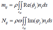
For the above solution problem, each disturbance potential фj(x, y, z) can be determined by an appropriate numerical solution method. After disturbance potential фj(x, y, z) defined, the generalized additional mass coefficient and the generalized wave-damping coefficient can be obtained by the following formula:
 (4)
(4)
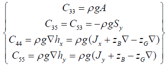
The resilience coefficient can be obtained by the following formula:
 (5)
(5)
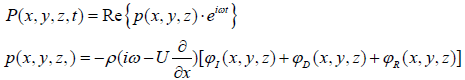
where, A is the waterline area of the ship at equilibrium;Sy is the static moment for the y-axis;Jx and Jy is the moment of inertia for the x and y axes;▽ is the ship's drainage volume; zB and zG is the vertical coordinates of the ship's center of gravity and center of gravity;hx and hy is the ship's horizontal stability and vertical stability are high. From the linearized Bernoulli equation, the hydrodynamic pressure after the hydrostatic pressure change is subtracted is:
 (6)
(6)
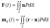
The hydrodynamic forces and moments acting on the hull can be integrated by the above-mentioned hydrodynamic pressure along its average wet surface S:
 (7)
(7)
Catenary model
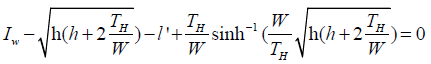
The catenary mooring cable has a standard quasi-static model equation, which is based on the vertical gravity action of the mooring cable to resist the resilience of the environmental load of the platform, whose equation is [16]:
 (8)
(8)
In Eq. (8), lw is the working length of cable when not stretched l’ is the length of cable after stretching, h is the water depth, TH is the cable tension, w is the gravity of the unit catenary line in the water. Catenary model is very effective in shallow water mooring calculation, so it has been widely used. This paper studies the mooring calculation of shallow water in a water depth of 30 m, so the catenary model is used.
Taking a LNG ship as an example, the ship's wave load is predicted by time domain potential flow theory, and the safety of the ship is analyzed and verified. The dock mooring design is carried out to calculate the mooring force of each cable based on the wave load and compare it with the specification value to verify the reliability of the mooring method. The main dimensions of the LNG ship are shown in Table 1. Different wave directions and wave frequencies have different effects on the radiation and diffraction of the ship, which affects the amplitude response of the RAO. The ship has a total of 0°, 30°, 60°, 90°, 120°, 150°, and 180°wave directions. The 0° direction is the ship's corresponding wave condition, and the 90°direction is the ship's starboard side wave. The 180° direction is the case where the ship is facing the waves. The wave frequency is set from 0.1 rad/s to 1.8 rad/s for a total of 35 frequencies with an interval of 0.05 rad/s. The wave uses JONSWAP (γ = 1).
| Overall length /m | Length between perpendiculars /m | Breath/m | Draft/m | Ballast draft /m | Full load draft /m |
|---|---|---|---|---|---|
| 195.3 | 184.8 | 30 | 20 | 6.723 | 10.3 |
Table 1: The main dimensions of the LNG.
Wave load calculation
Figure 1 is a distribution diagram of the wave bending moment of the ship. It can be seen from the figure that the vertical wave bending moment of the LNG ship is the largest when the wave angle is 0o-30o, that is, when the ship is sailing with the wave, its wave bending moment is larger than other wave angles. When the ship is sailing on a transverse wave, that is, when the wave angle is 90o, the ship receives the minimum wave bending moment. Figure 2 is a wave shear distribution diagram of the ship. It can be seen from the figure that when the ship's wave angle is 180o, the ship receives the maximum wave shear force. When the ship's wave angle is 120o, that is, when the ship approaches the transverse wave, its wave shear force is the smallest.

Figure 1: Vertical wave bending moment of LNG ship.

Figure 2: Vertical wave shear of LNG ship.
Motion response analysis
Figures 3, 4, 5, 6 and 7 are motion response curve of LNG ship in irregular wave, it can be seen from the picture and LNG carrier has large motion amplitude in the low frequency range. The surge RAO curve and sway RAO curve of the LNG ship is the largest when the frequency is 0.05 rad/s. The roll RAO curve and pitch RAO curve of the LNG ship is the largest when the frequency is 0.6 rad/s. The heave RAO curve of the LNG ship is the largest when the frequency is 0.8 rad/s.

Figure 3: Surge RAO.

Figure 4: Sway RAO.

Figure 5: Heave RAO.

Figure 6: Roll RAO.

Figure 7: Pitch RAO.
Calculation of minimum breaking force of mooring rope
In order to calculate the force and moment generated by the ship under the combined action of wind and current, the minimum breaking force of each mooring line is calculated based on the theory of time domain potential flow, which lays a foundation for the subsequent mooring design and calculation. The air density ρA=1.28kg/m3 and the seawater density ρw=1025kg/m3. The calculation conditions of the specific dock mooring force are shown in Table 2. All the calculated pitch angles are 0°in the mooring state.
| Draft(m) | Environment factors | Depth to draft ratio | ||||||||
|---|---|---|---|---|---|---|---|---|---|---|
| Structural draft | Ballast draft |
Wind (m/s) | Angle and speed of the current | Full load | ballast | |||||
| 10.3 | 6.26 | 30.87 | 0° | 10° | 50° | 90° | 180° | 1.1 | ||
| 1.54 | 1.03 | 1.03 | 0.386 | 1.54 | ||||||
Table 2: Dock mooring calculation conditions.
Calculated according to 14 broken cables:
Σy=2276=0.875A × 14+ 0.158 × 0
A=2276/(0.875 × 14+0.158 × 0)=185.8 kN
According to the specification, each rope can withstand up to 55% of the tension, so the minimum breaking force of each cable is MBL= 185.8/0.55=337.8kN:
Σx=651=0.893A × 0+0.235A × 16
A=651/(0.893 × 0=0.235 × 16)=173 kN
According to the specification, each rope can withstand up to 55% of the tension, so the minimum breaking force of each cable is MBL= 173/0.55=314 kN. Table 3 shows the wind receiving area, maximum longitudinal force and lateral force of the LNG ship under full load and ballast conditions. The minimum breaking force of each rope is MBL=314 kN, so the minimum breaking load of the cable is 314 x1.0= 314 kN. Therefore, as long as the minimum breaking of the actually taken mooring cable is not more than 314 kN and is greater than the minimum breaking force required in the calculation of the number of armors, it is satisfactory. The mooring calculation can be performed by substituting the above wind receiving area and wave load data into the mooring force calculation program.
| Conditions | Longitudinal wind area AL(m2) | Lateral wind area AT(m2) | Maximum longitudinal force FXmax (KN) |
Maximum transverse force |
|---|---|---|---|---|
| FYmax(KN) | ||||
| Ballast | 3203 | 873 | 651 | 2165 |
| full load | 2449 | 751 | 536 | 2276 |
Table 3: Ship's force and wind receiving area under two working conditions.
LNG ship mooring arrangement and preliminary calculation
Environmental settings for LNG ships
Environmental factors must be considered when designing the mooring system for LNG carriers. For ships of more than 16,000 DWT in global trade, effective and reasonable mooring settings can guarantee stability and safety. When a natural gas carrier exceeds 150 meters, environmental standards must be met. In this paper, the LNG ship first considers the axial direction of the three wind directions and the wave direction of 0°, 90°and 150°. The Jonswap wave spectrum is used. The specific environmental settings are shown in Figures 8, 9, 10 and Table 4 are Waveforms in an environmental state.

Figure 8: 0° wind direction and the environmental state of the wave.

Figure 9: 90° wind direction and environmental conditions of the wave.

Figure 10: 150° wind direction and environmental conditions of the wave.
| Wave | Wind | Current | ||||
|---|---|---|---|---|---|---|
| Significant wave height | Zero-crossing period | Wave direction | Wind speed | Wind direction | Current speed | Current direction |
| 1.5 m | 7.5 s | 0º | 10.29 m/s | 0º | 1.54 m/s | 0º |
| 0.3 m | 9.0 s | 90º | 7.72 m/s | 90º | 0.39 m/s | 90º |
| 1.2 m | 7.5 s | 150º | 10.29 m/s | 150º | 1.03 m/s | 150º |
Table 4: Specific environment setting of the LNG ship.
Cable guide hole setting for LNG ships
According to the OCIMF MEG3 (2008) specification, the initial mooring settings are shown in Figure 11. After calculation, the maximum axial force of the cable under ballast, full load conditions and different environments is shown in Table 5, and the maximum value appears as shown in Figures 12 and 13. Through the analysis of the above axial force, it is found that under each working condition, the maximum axial force is greater than the previously calculated 314 KN as shown in Table 5, which means that the ship has safety hazards in this mooring setting state and does not meet the design requirements. In addition, it can be seen that under different wind directions and working conditions, the maximum axial force of the ship mooring rope appears on different anchor chains, which proves that the ship is not only affected by different working conditions during the mooring process. It is also affected by environmental loads. In order to ensure the safety of the mooring ship, three wind directions (wave directions) were considered in the subsequent mooring setting.

Figure 11: 150° wind direction and environmental conditions of the wave.
| Direction | Ballast | Full load |
|---|---|---|
| 0° | 533.578 | 460.949 |
| 90° | 400.933 | 537.345 |
| 150° | 459.014 | 539.277 |
Table 5: Maximum axial force (N).

Figure 12: Maximum axial force of the cables on different wind directions and wave under ballast conditions.

Figure 13: Maximum axial force of the cables on different wind directions and wave under full load conditions.
Mooring position adjustment
After repeated calculations, comparisons and analysis, the ship's guide whole position is unchanged, but four fender points are added to ensure that the ship's wharf is moored, and the impact between the hull and the wharf is affected by wind, waves and current. Increase the cushioning force and reduce the damage to the hull. The position of the fender point is selected according to the mooring setting map. Because the water depth is 20 meters, the vertical position Z of the fender point is taken as 20 meters. The fender points and the relative positions of the 14 cables are shown in Figure 14. In Figure 14, there is an anchor point under each fender point to better secure the ship. And as can be seen from the Figure, the ship has a total of 14 cables, including 2 first cables, 6 horizontal cables, 4 inverted cables, and 2 tail cables.

Figure 14: Cable and fender point location.
Environmental adjustment
Due to environmental factors, the ship's mooring safety has a great impact. To ensure safety, the original 0°, 90°, 150° directions are modified to 0°, 30°, 45°, 60°, 90°. The six directions of 150°, the detailed settings are shown in Table 6. As can be seen from the table, in this adjustment plan, the ship adjusts the wind speed to the maximum wind speed specified in the design book and performs the mooring calculation in the worst environmental conditions, which is more helpful for the safety of the ship.
| Wave | Wind | Current | ||||
|---|---|---|---|---|---|---|
| Significant wave height | Zero-crossing period | Wave direction | Wind speed | Wind direction | Current speed | Current direction |
| 1.5 m | 7.5 s | 0º | 30.87 m/s | 0º | 1.54 m/s | 0º |
| 1.2 m | 7.5 s | 30º | 30.87 m/s | 30º | 1.03 m/s | 30º |
| 1.0 m | 8 s | 45º | 30.87 m/s | 45º | 1.38 m/s | 45º |
| 0.7 m | 8 s | 60º | 30.87 m/s | 60º | 1.76 m/s | 60º |
| 0.3 m | 9 s | 90º | 30.87 m/s | 90º | 0.386 m/s | 90º |
| 1.2 m | 7.5 s | 150º | 30.87 m/s | 150º | 1.03 m/s | 150º |
Table 6: LNG45 ship environment setting.
Adjusted calculation result
After the calculation of the environment, cable material and the addition of the fender point of the LNG ship, the final axial force calculation results under the two working conditions are shown in figure 15 it can be seen form the pictures, the breaking force of the cable under two typical working conditions is less than specification value, and meet the design requirement.

Figure 15: Axial force distribution of each cable under full load and ballast conditions.
Based on the unsteady time domain potential flow theory, the wave load of LNG ships under full load and ballast conditions is studied. Through short-term and long-term forecasts, wave bending moments and wave forces are obtained, as well as sway accelerations and surging accelerations that have the greatest impact on wave loads. Based on this, the wave force calculation is performed, and the mooring point is set according to the environmental conditions of the LNG ship dock mooring. Ultimately, the mooring force of each cable and the number of mooring cables required are required to meet the specifications. From the calculation of mooring force in this paper, it can be known that in the worst environment, the minimum breaking force of the cable is not only determined by the adjustment of the mooring system of the ship, but more importantly, the four fender points are set to the wave of the ship at the pier. The movement in the middle plays a buffering role. Not only protects the hull safety, but also acts as a “sponge pad” to cushion the impact force when the ship hits the dock. Such mooring settings take into account both the cable and the cross cable, which is more conducive to the balance of the ship.
Foundation item: National Natural Science Foundation of China (No. 51779135, 51009087), Shanghai Natural Science Foundation of China (Project approval number: 14ZR1419500).
Citation: Bao-Ji Z, Ping-Bo N, Chi Z (2019) Research on Calculation Method of Wave Load and Mooring Force Based on Time Domain Potential Flow Theory. J Def Manag. 9:180. doi: 10.35248/2167-0374.19.180
Received: 10-May-2019 Accepted: 21-May-2019 Published: 28-May-2019 , DOI: 10.35248/2167-0374.19.9.180
Copyright: © 2019 Bao-Ji Z, et al. This is an open access article distributed under the term of the Creative Commons Attribution License, which permits unrestricted use, distribution, and reproduction in any medium, provided the original work is properly cited.