Journal of Thermodynamics & Catalysis
Open Access
ISSN: 2157-7544
ISSN: 2157-7544
Research Article - (2017) Volume 8, Issue 3
Keywords: Dual impeller; Flow pattern; Mass transfer
Agitation is used to achieve homogeneity of the vessel content and increase the rate reaction by intensifying the number of collision between molecules. Hence, they are found in many operations such as precipitation, dissolution, crystallization, absorption and extraction. Therefore, they are found in a lot of chemical and petrochemical industries as well as water and wastewater treatment plants. They are characterized by low capital and operating costs compared to other mixing processes [1].
Recently, multiple impellers agitated vessels are receiving a lot of attention due to their low operating cost per unit volume compared to the single impeller. They are also very popular in biochemical industries, as they produce lower shear which preserve the living micro-organism for a longer time than single impeller. Finally, they are reported to be more energy efficient. Additionally, the combination of the different types of impellers can produce a lot of different flow patterns which can result in shorter mixing and reaction time [2,3].
Moreover, understanding the mass and heat transfer performance at the wall of the vessel is an important requirement for the role they play in the performance of catalyst, heat transfer accessories, and rate of diffusion controlled corrosion. Therefore. the aim of this study is to understand the effect of the vessel design on the flow pattern in double impeller agitated vessel and to study the effect of the resultant flow pattern on the rate of mass transfer at the wall of the vessel.
For the CFD analysis, a flat bottom vessel of height 30 cm and diameter 15 cm was used. Three different configurations were used depending on the combination of the impellers: a two Rushton turbine configuration, a lower pitched turbine and an upper Rushton turbine to form a pumping up configuration which means the liquid is pumped up axially from the turbine to be distributed radially by the Rushton. An upper pitched turbine with a lower Rushton turbine to form the pumping down configuration: the liquid is pumped downward from the turbine to the Rushton. The distance between the two impellers was varied: 5, 10 and 15 cm, while the lower impeller was always fixed at 5 cm from the bottom. Five different rotation speeds were used: 200, 300, 400, 500 and 600 rpm. COMSOL Multiphysics software was used for the finite element analysis. The magnitude of the velocity at a distance of 0.05 mm from the wall, which corresponds to the thickness of the nearest node to the wall, was calculated for comparison with the mass transfer data.
The frozen rotor option was used as it significantly reduces the required computational and the solution time. This feature simulates rotating flow by assuming that the topology of the system relative to the rotating reference frame is fixed [4]. The sensitivity analysis for the mesh size was checked until satisfactory results were obtained. For the mass transfer measurement, a plexiglass vessel with the aforementioned dimensions was equipped with Nickel electrode that were placed vertically at 3 cm apart on one side of the vessel (Figure 1). The other side was covered with a stainless-steel plate that acted as anode. The solution was composed of 0.01M K3Fe(CN)6 and 0.1M K4Fe(CN)6 dissolved in 1 normal Sodium hydroxide solution. The limiting current was determined at the different operating variables. The mass transfer coefficient was calculated according to the equation [5,6]:
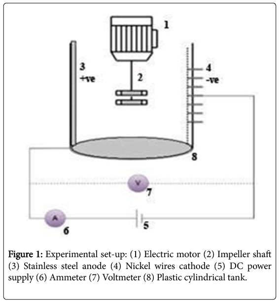
Figure 1: Experimental set-up: (1) Electric motor (2) Impeller shaft (3) Stainless steel anode (4) Nickel wires cathode (5) DC power supply (6) Ammeter (7) Voltmeter (8) Plastic cylindrical tank.
K=I1/zFAC∞………………(1)
Where A is surface area of the nickel electrode exposed to the solution (m2), ∞ is bulk species concentration (mole/m3), F is Faraday constant (96487 C/mole), IL is experimentally determined limiting current (A), z is electrons exchanged in electrode reaction, while K is mass transfer coefficient (m/s).
Mass transfer at the wall of agitated vessel
Figure 2 shows the measured local mass transfer coefficient at the different heights for the different configurations. As expected, the increase in the rotational speed results in an increase in the mass transfer coefficient. It is noted that the coefficient value increases at the position slightly above or under to the impeller. Furthermore, double Rushton impeller produces higher rates of mass transfer at the upper part of the vessel than the two other configurations, which indicates it produces a better homogenous flow. Also, pumping up produces higher rate of mass transfer than pumping down: pumping down flow is hampered by the closeness of the impellers to the bottom.
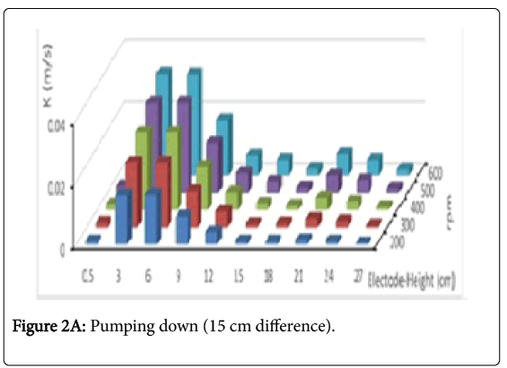
Figure 2a: Pumping down (15 cm difference).
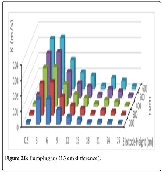
Figure 2b: Pumping up (15 cm difference).
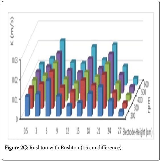
Figure 2c: Rushton with Rushton (15 cm difference).
Simulation of the flow pattern in the double impeller agitated vessel using Computational Fluid Dynamic (CFD)
Figure 3 shows the CFD simulation for the double impeller agitated vessel for pumping down, up and Rushton impellers for 600 rpm at different distance (d) between the two impellers. Figure 4 shows the estimated mean velocity at a distance 0.05 mm from the vessels’ wall.
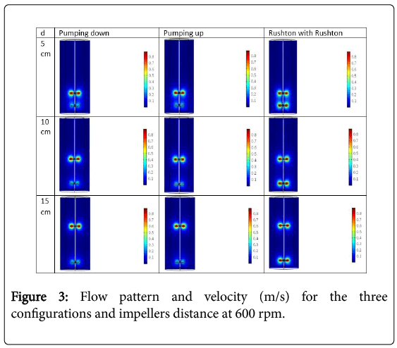
Figure 3: Flow pattern and velocity (m/s) for the three configurations and impellers distance at 600 rpm.
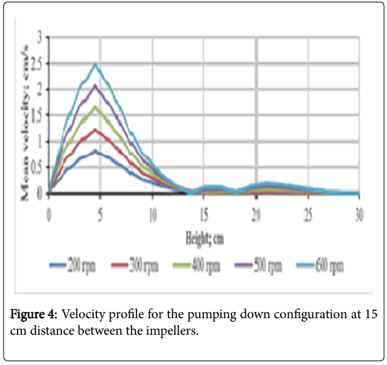
Figure 4: Velocity profile for the pumping down configuration at 15 cm distance between the impellers.
Correlation between experimental part and simulation
Previous studies [7,8] have shown that the mass transfer coefficient (K) is related to the velocity (v) according to the relation:
K=avn……………………(2)
where a, n are constants. Figure 5 shows the relation between the mass transfer coefficient, K, and the velocity at the node adjacent to the wall for the pumping down configuration at 15 cm distance between the impellers. It is seen that the results follow the relation closely, with the value of n for the different configurations and rotation speed is 0.63 with a standard deviation of 0.02. This value is closely related to previous studies [7,8]. On the other hand, the value of a varies according to the configuration and the distance between the impellers.
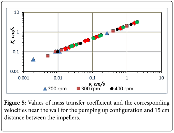
Figure 5: Values of mass transfer coefficient and the corresponding velocities near the wall for the pumping up configuration and 15 cm distance between the impellers.
The present study aims to clarify the flow pattern and wall mass transfer for the different configuration of double impeller agitated vessel. It is found that:
As the speed of the mechanical stirrer increases the rate of mass transfer at the wall increases.
• The double Rushton turbine produces more homogenous flow in the vessel, while the pumping up produces higher rates of mass transfer than pumping down.
• The rate of mass transfer depends on the impeller position. It is seen the high velocity and mass transfer coefficients in the upper or lower vicinity of the impellers that decay as we move away.
• The mass transfer coefficient was found to be proportional to the velocity at the wall to the power 0.63.
These results show the protentional usefulness of the CFD approach to estimate the flow pattern in the agitated vessel as well as the mass transfer at the wall of the vessel.