Advances in Automobile Engineering
Open Access
ISSN: 2167-7670
ISSN: 2167-7670
Research Article - (2018) Volume 7, Issue 1
The aim of this paper is developing a mechatronic control system to replace mechanical fuel injection system of a four-cylinder automotive diesel engine, to study what are the important electronics fuel injection parameters which have the highest effect on the engine performance. All the paper work performed on Isuzu engine 4HF1 which is 4 cylinder diesel engine working with fully mechanical fuel injection system. To develop mechatronics fuel system, must install crank sensor which measure the engine speed in rpm and specify the piston position, cam sensor which specifies the injection order, common rail fuel injection system which includes electronic injectors, high pressure pump and common rail, ECU which control all the system inputs and outputs, and injectors driver controller which responsible for delivering the required high voltage for the injectors with high speed switching. ECU software will be developed from scratch to develop injection quantity, injection time and injection order output signals to be compatible with the common rail fuel system. Mathworks tools (Matlab-Simulink-Stateflow) will be used for developing ECU software application layer which divided into many models as crank shaft speed model, crankshaft sensor piston position, cam sensor injection order model,pedal speed model, injectors model, torque model and final model which collect all the previous models. Embedded coder toolbox will be used for generating C code which will be integrated with the microcontroller layer and uploaded to the selected ECU.
<Keywords: Internal combustion engine; Internal combustion engine embedded system; Internal combustion engine management; Internal combustion engine software; Internal combustion engine ECU; Diesel engine Technology; Diesel engine ECU.
The Internal combustion engine is one of the fastest growing industry in the world since it is the heart of a lot of applications as automotive industries, heavy equipment, power generation and a lot of other applications, so there is a big need to enhance the performance for internal combustion engine continuously [1]. Engines manufacturer expenses a lot of money on research and development trying to figure out a lot of new enhancements of many parameters as, decreasing fuel consumption, sounds, vibration, emissions and increasing power and torque. Mechatronics now plays an important role in these enhancements, so most of the internal combustion engines now contains a lot electronics and controllers so in this paper a mechatronic control system will be developed to replace mechanical fuel injection system of a four-cylinder automotive diesel engine, to study what are the important electronic fuel injection parameters which have the highest effect on the engine performance.
CAM sensor and reluctor wheel installation
Due to overhead cam tight area which not allow installing any reluctor wheel, small separate tooths machined and stuck on the camshaft gear, three and the fourth is wider than others to be the marked tooth, tooth thickness 0.5 cm, tooth width 0.9 cm and the wider tooth width 2.7 cm, since the space between the camshaft gear and the rocker arm end is 0.41 cm so there is no enough space for the tooth to rotate freely without hitting the rocker arm. So, for free rotating the rocker arm grinded 1.5 mm (Figure 1) [2].

Figure 1: Rocker arm before and after grinding.
Rocker arm before and after grinding to install the first tooth, crankshaft rotated until piston one at TDC in combustion position 3rd stroke then the first tooth fixed which is the wider stuck it on the cam gear directly under the cam sensor surface area, the second tooth installed after first tooth by 90 degrees, after other 90 degrees the third and finally the fourth tooth so, when the cam sensor detecting the wider tooth this means that the piston 1 in the position of fuel injection. Cam sensor installation the overhead engine cover drilled with diameter 1.33 cm to fit the sensor (Figures 2-4).

Figure 2: CAM sensor tooth installation.

Figure 3: CAM sensor installation and testing the CAM sensor and tooth signal.

Figure 4: CAM sensor signal detected by oscilloscope.
Crank sensor and reluctor wheel installation
There is a special hole already exists at the flywheel housing with diameter 1.75 cm fitted for the crank sensor, a special reluctor ring machined to be fitted over the flywheel and directly under the hole with diameter 42 and 59 tooths (Figure 5).

Figure 5: Reflector wheel installation over the flywheel.
Since the isuzu 4HF1 manufacturer mark crankshaft pully with marks which specify piston position in degrees before TDC, so for reluctor wheel installation, crankshaft rotated until reach the 12 degrees mark then the reluctor wheel installed with consideration the missing tooth will be under the sensor surface area directly, this means, when detecting marked tooth the piston will be before the TDC by 12 degrees (Figure 6) manufacturer made hole with 1.75 cm diameter at the gearbox casing which can fit the crank sensor and will be directly over the reluctor ring (Figures 7 and 8) [3-5].

Figure 6: The missing tooth.

Figure 7: Testing crank sensor by oscilloscope.

Figure 8: Crank sensor signal detected by oscilloscope.
Installing the electrical injectors selected injector
Siemense common rail electronic injector with part number 9636819380. The main reason for selecting this injector, it has same geometry of the Isuzu injector and same diameter, so there is no need to make any modification on the engine cylinder head, but there are other differences as follows:
1. There is a small difference in dimension at the middle of the injector but it solved by made a little grinding at the middle of the injector body [6,7].
2. The injector body does not have the compression seal as in the Isuzu injector so it grinded for seal installation (Figure 9).

Figure 9: Injector after grinding and making seal groove.
3. The Siemens injector comes with ignored nozzle hole angle data so it replaced with Denso nozzle (ND-DLLA 154P717). which has same Isuzu injector nozzle specs 5 × 0.215 × 154 and same nozzle diameter, but there is a difference in nozzle length (Figure 10). Siemens common rail injector length problem solved by made a special ring seat, installed under the injector seat and since the Siemens injector nozzle length 22.5 mm and Isuzu injector nozzle 21.3 mm the ring thickness is the difference=1.2 mm and machined to has the same geometry as original injector nozzle seats as photos (Figure 11).

Figure 10: Siemens common rail injector.

Figure 11: Machining of the seat ring upper face to fit with the old seat.
4. The Isuzu injector tighten socket could not be used with the common rail injector due to the geometry of the electronic solenoid and this problem solved by made a special new one (Figures 12 and 13) [8].

Figure 12: Injector tighten socket.

Figure 13: After installing the injectors.
Common rail pump and rail installation
It is a high-pressure pump (1600 bar), only responsible for injecting a high pressure fuel in the common rail, so it does not control any thing or have any effect on engine injection timing which allow to replace it is external gear with any one suitable with the engine, but the main problem is the pump geometry and dimensions, since the area which the Isuzu inline pump is installed is not big enough, this problem solved by removing the power steering pump and using it is place for the common rail pump (Figure 14).

Figure 14: Installing common rail with inlet and return pipes.
The rail installed upper the pump since there a fixation area available already by Isuzu manufacturer made installing common rail with inlet and return pipes [9].
ECU
Engine manufacturers usually use expensive high quality processor to guarantee high processing speed and zero errors since it working with hard real time software, according to the project low-cost, raspberry pi with the following specs will be a suitable choice: raspberry Pi 3 Model B a quad-core 64-bit ARM-Cortex A53 clocked at a 1.2 GHz.
Injectors driver controller
This controller responsible for transferring the signal from the ECU to the injectors in high-speed switching with write voltage [10].
Injectors driver controller circuit includes:
1. DC-DC Boost Converter 8-32 V to 45-390 V since the common rail injectors is a piezoelectric type with 100 V.
2. TIP31C transistor used for high speed switching with high dc voltage due to injector high voltage at 100 V DC.
Installing and calibrating potentiometer (Speed pedal)
The potentiometer will work as speed pedal sensor to increase the engine speed (Table 1). Typical powertrain control strategies contain several hundred thousand lines of C code and thousands of associated parameters and calibration variables requiring thousands of man-hours to calibrate, although the ongoing efforts in self-calibrating approaches and tools may substantially reduce this time-consuming task. Mathworks tools play important role in design the embedded system algorithms for Automotive industry. Using Mathworks products, Simulink, Stateflow and Embedded coder allow generating C code which can be ported to the microcontroller.
| Incremental point | Volte |
|---|---|
| 0 | 4.989 |
| 1 | 4.713 |
| 2 | 4.174 |
| 3 | 3.705 |
| 4 | 3.153 |
| 5 | 2.650 |
| 6 | 1.995 |
| 7 | 1.355 |
| 8 | .783 |
| 9 | .403 |
| 10 | .014 |
Table 1: Potentiometer calibrating data.
The AUTOSAR architecture distinguishes on the highest abstraction level between three software layers: Application, Runtime Environment and Basic Software which run on a Microcontroller.
Mathworks tool (Matlab, Simulink, Statesflow and Embedded Coder) will be used to develop the application layer as follows:
1. Crank sensor speed model
2. Crank sensor piston position model
3. Cam sensor injection order model
4. Pedal speed sensor model
5. Injectors model
6. Torque model
7. Final model
Before starting software developing there is an important note must be taken into consideration through software developing, changing the injection frequency will decrease or increase the engine rpm but changing the fuel injection quantity will decrease or increase the engine load (Figure 15).

Figure 15: Crank sensor speed model.
This model measure the engine speed (rpm), it will count every high pulse detected by the crank sensor and since the reluctor wheel is 59 tooths, when sensor detects 59 high signal, this will be one rpm, Simulink model blocks:
1. Model starting with comparing block to compare the pulse high or low.
2. The results of comparing will be input to if condition block, if it 1 means signal is high and will store 1 in data store A, if 0 means signal is 0 and will store 2 in the data store B.
3. Comparing data store B with 2, if correct then the output will be 1 and if false the output will be 0.
4. Comparing the result of comparing data store B and data store A with AND logic block, if the result is 1 this means the pulse is high.
5. The output of AND logic block will be input to switch block, if the input is one then the output will be 1 going to the counting cycle which will start to count 1, this means the first detection of a high signal,in same time the datastore block A and B will be reset to be zero value.
6. In case the output of the switch block is 0 then there is no any added value to counter, in same time the values of datastore block A and b will be same values, for example when model started and if block detect one then the datastore A block will be 1 and no any add to store B, if datastore B still contains zero due to reset with 0, the output of AND 1 0 will be 0, means no detection for high pulse and the values of data stores blocks will be same, this because the signal may be high but also it is may give 1 at start of high or middle or end or through any point on the pulse width, so this value will not be detected as high until detection of zero occur, in this case the datastore B will be 2 and AND logic block will give 1 and the signal will be detected as high (Figure 16).

Figure 16: Crank model testing with simulated crank sensor signal.
This model will compare every tooth width with the next one until detecting the wider one, the model has five subsystems blocks (first tooth subsystem block-next tooth-model reseting-comparingindependent subsystem block). Starting with crank speed model, after detecting the high pulse the output of the AND logic block will be input to the K datastore block and the independent subsystem Block which contains the following blocks :
1. F datastore connected to increment stored integer block with initial value 0.
2. J datastore connected to decrement stored integer block with initial value 4.
3. Enable block, every time this subsystem receiving 1 it will decrease the datastore J and increase the datastore F block by 1.
Model reseting subsystem it used to reset F and J datastore blocks. The data store F block starting initially with 0 then increased to 1 then 2 and reset to 0 value when it reaches 2.
The J block will starting initially with 4 then decreased to 3 then 2 then 1 and reset to 4 when it is value reaches 0. The first tooth subsystem itis enabled subsystem contain counter which start counting when enable block receiving 1 from the main input signal, the result of this counter will be input to switch block and will be added to the C datastore block in case the value of datastore F is 1, if not equal 1 it will keep the same previous value of datastore C as it is.
When model running, at the beginning the datastore block F initial value is 0, once high signal detected, the block will be increased by 1 so itis value will be 1 then the counter will store the counting value in the C datastore block, once another detection of high the datastore F will be increased by one to be 2, so the C block value will be the same previous value and the Block F will be reset to be zero value, after another detection will be increased by one to be 1. At the end when value of F block reach 0 the value of C will be added to X output block. The next tooth subsystem itis enabled subsystem contain counter which start counting when enable block receiving 1 from the main input signal, the result of this counter will be input to switch block and will be added to the D datastore in case the value of datastore J is 1, if not equal 1 it will keep the same previous value of datastore D as it is.
When model running at the beginning the datastore block J initial value is 4 and once detection of high signal the block value will be decreased by one to be 3, the counter will not store the counting value and the value of D datastore will be the same which initially zero, and once another detection of the block by other high signal the datastore J will be decreased by one to be 2 so the D block value will be the same previous value and after another detection will be decreased by one to be 1, the counter value will be stored in D datastore block, another high detection will decrease the J value by 1 to be 0, which will reset the J block value to be 4 as initial value. At the end when value of J block reach 4 the value of D will be added to Y output block then will compare the value of X with the Value of Y as follows:
1. If same counting value, this means that the pulse width is the same which will give 0.
2. if different values this means that the pulse width is different and this is the marked wider tooth and will give 1 value (Figure 17).

Figure 17: Crank model tested with simulated crank sensor signal.
Crank sensor model injection time
The crank model will start injection before TDC by 9 degrees and since the crank sensor reluctor wheel installed to consider when detecting the marked tooth, the piston will be before TDC by 12 degrees so the model developed to count one pulse and half after detecting the marked tooth for cylinder 1 injection time, for next cylinder injection time the model will count after detecting the marked tooth by 181.5 pulses.
CAM senor model injection order
The cam model injection order 1 3 4 2. The cam sensor reluctor wheel has four tooths, after detecting the marked tooth will inject cylinder 1 and when detecting the next pulse will inject cylinder 3, next will be cylinder 4 then cylinder 2.
Using embedded coder toolbox, C code will be generated and manually integrated with the ECU input and output pins.
Part of crank sensor model generated C code:
* Model version : 1.26
crank_final_working_raspi_code_generation.c
* Code generated for Simulink model ‘crank_final_working_raspi_ code_generation’
* Simulink Coder version: 8.12 (R2017a)
* Target selection: ert.tlc
#include “crank_final_working_raspi_code_generation.h”
#include “crank_final_working_raspi_code_generation_private.h”
#include
/* Exported block signals */
int crankout; /*
/* Block states (auto storage) */
DW_crank_final_working_raspi__T crank_final_working_raspi_ co_DW;
/* Real-time model */
RT_MODEL_crank_final_working__T crank_final_working_ raspi_co_M_;
RT_MODEL_crank_final_working__T *const crank_final_ working_raspi_co_M=
&crank_final_working_raspi_co_M_;
/* Model step function for TID0 */
void crank_final_working_raspi_code_generation_step0(void) /* Sample time: [0.001s, 0.0s] */
{
while
{
wiringPisetup();
pinMode(23,INPUT);
crankin-digitalRead(23);
printf(“crankout=%d\n”,crankout);
int32_T rtb_Switch4;
real_T rtb_Sum1;
uint16_T rtb_FixPtSum1;
uint16_T rtb_FixPtSwitch;
datastorea=A;
datastoreb=B;
rtb_Switch4=((A !=0.0) && (B==2.0));
rtb_Sum1=(real_T)rtb_Switch4 +
crank_final_working_raspi_co_DW.Memory1_PreviousInput;
Speed pedal model is used for determining the driver’s wish so it works as input for the driver wish map to calculate the fuel injection quantity (Table 2).
| Incremental point | volte |
|---|---|
| 10 | 4.989 |
| 9 | 4.713 |
| 8 | 4.174 |
| 7 | 3.705 |
| 6 | 3.153 |
| 5 | 2.650 |
| 4 | 1.995 |
| 3 | 1.355 |
| 2 | .783 |
| 1 | .403 |
| 0 | .014 |
Table 2: The model consisting of one lookup table contains potentiometer calibration data.
Torque model
In diesel engine the mass of air is constant but the mass flow rate is variable at variable speed, so at constant speed, the only variable in air to fuel ratio is the mass of fuel which will control the engine load by increasing or decreasing the fuel quantity. This model is used for calculating the engine required fuel injected quantity trough two lookup tables:
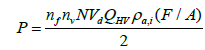
The first lookup table is driver wish map which used for calculating the fuel injection (Figure 18 and Table 3) quantity according to two inputs rpm and Pedal sensor value and will be created using the following equations:

Figure 18: Torque model.
| RPM | Period (sec) | volume |
|---|---|---|
| 520 | 116 secs | 10 ml |
| 1380 | 52 secs | 13 ml |
Table 3: Practical fuel injection volume for 4HF1 zexel pump and zexel injector at different rpm.
From this table we can calculate practically the injector injection quantity at 520 rpm and 1380 rpm at no load in mg/stroke:
At 520 rpm with no load and 116 sec, the injection quantity for one injector is 10 ml.
Convert the 10 ml to mg=10 × 840=8400 mg.
The fuel injected per second for one injector=8400/116=72.413 mg/ sec and to convert it to mg/stroke, number of injector strokes in one sec must be calculated as follows.
Engine rotations per sec=520/60=8.6, since the enigne is four stroke engine so each injector will stroke once every four strokes which every two crank rotation, so for 8.6 rotations per sec the injector will stroke 8.6/2=4.3 strokes, it mean the injector will inject 4.33 times, so the injection quantity for one injector at 520 rpm=72.4/4.3=16.72 mg/ stroke.
At 1380 rpm with no load and 52 sec the fuel injection for one injector is 13 ml, convert ml to mg 13 ml=13 × 840=10920 mg.
The fuel injected per second 10920/52=210 mg/sec
Engine rotaions per sec=1380/60=23
So for 23 rotations per sec the injector will stroke 23/2=11.5 strokes then the injection quantity at 1380 rpm=210/11.5=18.26 mg/stroke (Table 4).
| Pedal (rpm) |
0 (%) |
10 | 20 | 30 | 40 | 50 | 60 | 70 | 80 |
|---|---|---|---|---|---|---|---|---|---|
| 200 | 91.87 | -------- | -------- | ---------- | --------- | ---------- | ---------- | ---------- | |
| 550 | 16.72 | -------- | -------- | ---------- | ---------- | ---------- | --------- | ---------- | ---- ---- |
| 965 | 17.49 | 23.17 | 28.85 | 34.63 | 40.21 | 45.89 | 52.42 | 57.26 | |
| 1380 | ---------- | -------- | 18.26 | 28.31 | 38.32 | 48.36 | 58.40 | 68.4 | 78.47 |
| 1795 | ---------- | -------- | -------- | 18.68 | 30.88 | 43.09 | 55.29 | 67.41 | 78.88 |
| 2210 | ---------- | -------- | -------- | ---------- | 20.75 | 35.11 | 48.78 | 63.83 | 78.19 |
Table 4: Calculation of other wish driver map points.
For Isuzu diesel engine, Volumetric efficiency is 0.8, Fuel conversion efficiency assumed 0.3, Heating value=44800000 j/kg.k, cylinders volume=4334cc=0.004334 m3 and from engine performance curves at 1380 rpm, power=40.617 KW and torque=280.5 NM.
Calculation for fuel injection quantity at 1380 rpm with 80% peddal pressed 280.5=0.3 × 08 × 448000 × 0.004334 × (f/a)/12.56
F/A=0.0756 each cylinder volume=4334/4=1038 cc=1038 mg and in mg/stroke=1038 mg/stroke
F/A=0.0756=Mfuel/Mair.
Mfuel=1038 × 0.0756=78.47 mg/stroke.
Since 1380 rpm engine speed cannot achieved by pressing on the peddal less than 20% to 80%, So at 1380 rpm the calculations will be only for 20%, 30%, 40%, 50%, 60%, 70% and 80%.
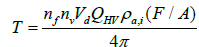
From practical test at 1380 rpm with 20% peddal pressed with no load: F/A=18.26/1038=.01759,so the torque T=0.3 × 0.8 × 44800000 × 0.004334 × 0.01759/12.56=65.26 N.M.
For the other points, Torque step=280.5-65.26=215.24 NM, 215.24/6=35.87 (Table 5).
| Pedal % @1380 | Power @1380 KW | Torque @1380 NM |
|---|---|---|
| 0 | ---------- | ----- |
| 10 | -------------- | ------- |
| 20 | 9.42 | 65.26 |
| 30 | 14.62 | 101.13 |
| 40 | 19.80 | 137 |
| 50 | 24.98 | 172.87 |
| 60 | 30.17 | 208.74 |
| 70 | 35.35 | 244.61 |
| 80 | 40.54 | 280.5 |
Table 5: Injectror testing results of Pedal %, Power and Torque @1380 NM.
At 30% peddal and at 1380 rpm the power=14.62 KW and torque=101.13 NM so for fuel quantity: 101.13=0.3 08 × 44800000 × 0.004334 × (F/A)/12.56.
Mfuel=0.027 × 1038=28.31 mg/stroke.
At 1380 rpm and with 40% peddal pressed, the torque is 137, F/ A=137/3710.124=0.036.
Mfuel=036 × 1038=38.32 mg/stroke, and same calculation for other points. Second look up table is to convert the injection quantity to pulse width (Table 6).
| Injection quantity (mg) | Injector pulse width (m/sec) |
|---|---|
| 10 | .2 |
| 35 | .7 |
| 60 | 1.2 |
| 80 | 1.6 |
| 105 | 2.1 |
Table 6: Common rail injectror testing results of Injection quantity (mg) and Injector pulse width (msec).
Injectors Model
This model for switching the 4 injectors with specific injection order and specific pulse width modulation signal.
The model contains
PWM subsystem block which generates variable frequency variable duty cycle pulse width modulation signal according to the input data of duty cycle and engine frequency.
Flowstate chart
The Stateflow chart used for specify the injector fuel injection order and injection time according to it is inputs which are the cam sensor signal, the crank sensor signal and the PWM signal (fuel injection quantity) (Figures 19 and 20).

Figure 19: CAM sensor signal, the crank sensor signal and the PWM signal (fuel injection quantity).

Figure 20: Final model which collecting all the previous models.
ECU C Code
The Generated C Code from every model will integrate togeather manually then will integrate with the microcontroller layer which define all the controller hardware input and out pins, these pins will integrate with the input and output of the application layer. At the end, this C code will compile and uploaded to the controller for starting the engine.
The engine started but not efficiently since there is a hunting and when trying to increase the rpm, the engine shut off, from this problem we can specify the important electronics fuel injection parameters which have the highest effect on the engine performance since this problem causes be as follows: 1-At engine speed 420 rpm, the engine must inject at least three times per second and it is clear from the below oscilloscope reading that there is lag in the injection pulses, this may be caused be the following Figure 21. Lag in the processor speed since the raspberry pi is initially loaded with the Linux operating system. Transistor quality, which is not fast as required. Transformer quality which causes a lag in the converting volt. Wiring and connectors quality may cause lags in the system also, wiring length since shorted the wires improved the engine starting. Due to the size of the tooths, the tooths material and the way of installing, the cam sensor tooths signal have a problem. From the piezoelectric injector testing results and the engine software, injector injection timig is too small since the working range is 0.2 to 2.6 millsecond (600) microseconds which need a very efficient system to work with as CAN network. Any lag in the processor speed will causes increase or decrease in the response of the injector opening and closing which will cause wrong injection quantity.

Figure 21: The oscilloscope reading for injectors signal at 420 rpm.
The high-pressure fuel injection system increase the fuel pressure and speed which may be causes spreading the fuel into waves which hitting the cylinder walls and causes reflections and interferences which makes incomplete combustion. The injection quantity values in driver wish map (torque model/injection quantity lookup table) may be inaccurate and also the injector pulse width in the second lookup table may be not accurate hence the injector may inject more or less fuel than the required. The software may be need improvement to increase the speed of processing. The injection timing for the mechanical system before the TDC by 12 degrees but for the mechatronics system this not starting the engine and started at 9 degrees before TDC, so with variable speed this value should be variables.