Advances in Automobile Engineering
Open Access
ISSN: 2167-7670
ISSN: 2167-7670
Research Article - (2016) Volume 5, Issue 2
Carbon dioxide is a major cause of natural calamities and changes in climatic conditions. Of all the sources of emission, the amount of carbon dioxide from automobiles is approximately 65%, which is more than any other sources of emissions. Raise in carbon dioxide content in atmosphere is causing global warming which is evolved from greenhouse gases. To reduce the emission and control of carbon dioxide percentage in atmosphere form automobiles, theoretical and practical methods of adsorption of carbon dioxide using activated charcoal (carbon) in diesel operated engines is conducted. Charcoal is one of the best adsorption material due to its high pours valve and capture capacity, when reacted with other reagents in order of activation, it increases its adsorption capacity than that of regular charcoal. In this project the activation of charcoal is steam activation. The amount of carbon dioxide exhausted from diesel engine in ideal condition and after the reactor chamber is added to the exhaust system the content of carbon dioxide is controlled up to 9.266%.
<Keywords: Control of carbon dioxide; Adsorption; Activated charcoal; Steam activation; Emission; Smoke test
Carbon dioxide is the one of the gases in atmosphere bearing percentage of 0.04, it plays an important role in maintaining optimal condition of earth by enriching photosynthesis in plants and other benefits, but it has also become a major issue in the recent decade due to its increase in percentage leading to increasing the global temperature, which causes melting down of glaziers and increasing water levels, heavy changes in temperature.
There are two major sources of carbon dioxide, natural and human. Natural sources are ocean-atmosphere exchange, plant and animal respiration, soil respiration and decomposition and finally volcanic eruption. Human sources are fossil fuel usage, land use changes and industrial process. Carbon dioxide is the primary greenhouse gas emitted through human activates, the main activate that emits carbon dioxide is the combustion of fossil fuels (coal, natural gas and oil) for energy and transportation, although sustain industry process and land use changes also emit carbon dioxide. The main sources of carbon are diode, car, electric, transportation and industry. Carbon dioxide is constantly being exchange among the atmosphere, ocean and land surface as it both produce and adsorb many microorganism, plants and animals.
However, emissions and removal of carbon dioxide by this natural process tend to balance. Since the industrial revolution began around 1750, human activity has contributed substantially to the climatic change by adding carbon dioxide and other heat trapping gases to atmosphere.
Rajadurai et al. [1] the efforts of humans to gain more energy output is dearly costing the entire planet in phase of carbon dioxide, emission of this gas can be controlled by implementing some major changes at the source of emissions. An inventive trend of using a chamber at the tailpipe of an exhaust system, which traps and stores the carbon dioxide from the exhaust gases. Modified charcoal made of coconut trunk and stem is used to trap and store carbon dioxide from the exhaust gases. The theory of storage and using of carbon dioxide can be helpful in many other industrial which uses carbon dioxide for many other purposes [2-4].
Valentinas Mukunaitis et al. [5] the total content of carbon dioxide emissions from diesel operated engine is lesser than that of petrol engine, in numerical terms its 27% and 17% petrol and diesel respectively. When the engine displacement is high then the consumption of fuel is also high.
Catalytic convertor is another major part which plays an important role in the exhaust system, the process of oxidation and reduction of on dangerous gases emitted from the exhaust gases, there are also major break through which helps in improving the performance of catalytic convertor without any changes their properties, like back pressure and flow of gases [6,7].
In order to reduce carbon dioxide from the automobile exhaust emission we used granular activated charcoal which has diffusion of adsorbate is thus an important factor this carbons are suitable of adsorption of gases and vapours, because they diffuse rapidly (Table 1). Granular carbon are used for water treatment, deodorization and separation of components of flow system and also used in rapid mix basins (Figure 1).
|
Engine Make |
Volkswagen Jetta 2.0L |
|
Displacement |
1968cc |
|
Bore |
82.5mm |
|
Stoke |
92.8mm |
|
Emission Standards |
Bharath standards IV |
|
Maximum Power |
425HP |
|
Exhaust Specifications |
Three way convertor |
|
Compression Ratio |
10.5:1 |
|
Fuel Type |
Diesel |
Table 1: Specification of the engine.

Figure 1: Jetta vehicle 2.0 L.
Gas analyser
Gas analyser is a device which is used to measure the content of various gases present in a system or surroundings (Table 2). Here it is used in measuring the content of hydrocarbons, carbon monoxides, carbon dioxide and nitrogen and lamda present in the exhaust gases of and engine [4].
| Measured quality | Measuring range | Resolution | Accuracy |
|---|---|---|---|
| CO | 0.0-15% vol | 0.01 % vol | 0-10 ±0.02% abs ±3% rel 10.01-15% ±5% rel |
| CO2 | 0.0-20% vol | 0.01 % vol | 0-16% ±0.3% abs ±3% rel 16.01-20% ± 5% rel |
| HC | 0.0-30000 ppm | ≤2000: 1 ppm vol >2000: 10 ppm vol |
0-4000ppm ± 8ppm 3% rel 4001-10000ppm 5%rel 10001-30000ppm 10%rel |
| O2 | 0.0-25% vol | 0.01 % vol | ± 0.02 % abs 1% rel |
| NO | 0.0-5000 ppm vol | 1 ppm vol | ± 5 ppm 1% rel |
| Engine speed | 400-6000 min-1 | 1 min-1 | ±1% of ind val |
| Oil temperature | 0.0-125 °C | 1°C | ± 4°C |
| Lambda | 0.0-9.999 | 0.001 | Calculation of CO,CO2,HC,O2 |
Table 2: Techinical specification of gas analyser.
The techinical specification of a gas analyser are as follows (Figure 2).

Figure 2: Gas analyser.
Activated charcoal
Activated carbon is a type of carbon that is activated and carefully controlled oxidation process to improve pours structure of carbon. The improper structure of carbons in a high degree of pourcity and over a board range of pour sizes, vizable cracks and minure to gaps and voids of molicular dimentions the determined structure of carbon will gives it a very large surface area which undergo the carbon to adsorbe a huge anount of carbons molucules (Table 3).
| Shape | Granular |
| FC | 75% Min |
| VM | 17% Max |
| Ash & Foreign Matter | 5% |
| Max Moisture | 16% |
| Grade | 4x8 USS mesh |
| Passing Through | 4.75mm X 2.36mm |
Table 3: Specification of activated charcoal.
Activated carbon has hieght of voloumn to adsorbing pourcity of any kind of material that is aviliable in mankind (Figure 3).

Figure 3: Ingredient for surface coating of coconut shell charcoal using ZnCl2.
The ingredients needed to prepare the coconut shell catalyst are as follows:
• Charcoal: 1400 gm
• Zinc chloride: 56 gm
• 1400 ml of distilled water was taken in a beaker.
• 56 gram of ZnCl2 was added in the beaker.
• Both the ZnCl2 and distilled water were mixed to form a solution.
• 950 gram of coconut charcoal was added inside the solution beaker.
• The mixture was tried continuously to have a better coating on the coconut charcoal.
• The coated sample was heated treated in furnace for 14 hours at 85°C.
Design calculation
The catalytic convertor is designed with the following three objectives:-
• Simple construction (No complicated construction).
• To obtain a greater Surface area.
• To reduce the back pressure.
• The network output per cycle from the engine is dependent on the pumping work consumed, which is directly proportional to the backpressure. To minimize the pumping work, backpressure must be low as possible. The backpressure is directly proportional to the catalytic converter design. The catalytic substrate and shape of the inlet cone does not contribute to the backpressure [6,7].
• The cylindrical shape was considered due to ease of fabrication, minimum assembly time, rigidity and easier maintenance.
Space velocity
The time necessary to process one reactor volume of gases is as follows:
Calculation for Determination of Diameter and Length:
Assuming Space Velocity = 16000 m/hr.
Volume flow rate = Swept volume × Number of Intake stroke per hour

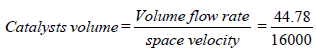
Volume of Catalyst = 0.0027 m3.
Shell dimension
The Shell is the cylindrical part between the inlet and outlet cones. Activated charcoal will be placed inside this shell.
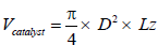
Where D= Diameter of the catalyst
L= Length of the Catalyst
L= 3D (Assume)
0.0027 = 0.785 × D3 × 3
D = 0.103 m
L = 3D
L = 3 × 10⁸
L = 309 mm
Expermental layout
This flow chart explains about experiential work that deals with the adsorption of carbon dioxide. The diesel operated engine’s exhaust is connected to the after-treatment system, which leads to muffler which reduces the turbulence or the flow in gases and passes through the intermediate valve [8-10]. Which is connected to two way valve, where the connection leads to atmosphere and the other leads to a experiential setup connected to flow meter, in the first connection, when there is over flow of gases, open the two way valve to the atmosphere till we get the constant flow. If a constant flow is generated then we close the secondary valve and open primary valve which is connected to flow meter. Flow meter now shows the mass flow of gases from the exhaust towards the reactor chamber (Figure 4).

Figure 4: Flowchart of experiment setup.
Then further a two way valve is fixed to collect the sample gas and measure the content of gases present in the flow, this flow of gas is passed through the reactor chamber where the reaction (adsorption) is taken place and then a second sample is taken to measure the content of gases absorbed in the reaction chamber. Then the gases are passed out the atmosphere [11,12].
The validation of design is done using catia and CFD analysis, this involves various stages of procedures as follows, It is necessary to test Pressure drop and flow uniformity index in CFD analysis (Figures 5 and 6).

Figure 5: Reactor chamber.

Figure 6: Flow in a reactor chamber.
CFD analysis
Below Figure 7 shows the pressure drop obtained in both cases:

Figure 7: Charcoal chamber.
Case A – Charcoal Chamber, (Flow through top to bottom).
Case B – Charcoal Chamber, (Flow through only cone).
Below, Figure 8 shows the pressure drop between two cases. For Case A, the observed pressure drop is 75.045 mbar; for Case B, the observed pressure drop is 65.538 mbar. The calculated pressure drop is within target criteria. Hence, it will not affect engine performance (Table 4).
| Domain | Type | Value |
|---|---|---|
| Inlet | Mass Flow rate | 195kg/h |
| Outlet | Pressure | 1atm |
| Inlet | Temp | 2000C |
| Outlet | Temp | 300C |
| Reaction Chamber (charcoal) | Porosity | 0.89 |
Table 4: Boundary condition.

Figure 8: Absolute pressure drop.
Uniformity index
Below, Figures 9 and 10 shows the uniformity plot of Activated Charcoal chamber, respectively. The reactor chambers’ uniformity is 0.889; however, the target is >0.90 for initial confirmation of the analysis. To reach the uniformity target, inlet and outlet cone optimization is done.

Figure 9: CFC uniformity plane section at inlet of alumina chamber.

Figure 10: Uniformity plot of alumina reactor front face.
Layout fabrication
A wire mesh is rolled in the cylinderical shape with the same or lesser dimentions of the reaction chamber. With both closed ends, as shown in the Figure 11 below. Which is filled with activated charcoal in it [13].

Figure 11: Wire mesh filled with charcoal.
Then that wire mesh is imposed in to the reaction chamber where the adsorption process takes place, the below Figure 12 shows the reactor chamber with activated charcoal wire mesh [14].

Figure 12: Reactor chamber.
This is fixed to the setup, where the experment is carried out, the expermental layout is shown below in step by step procedure (Figure 13).

Figure 13: Reactor chamber with wire mesh containg activated charcoal as catalyst.
The test on Co2 reactor chamber is conducted on Volkswagen Jetta TDI 2.01 with automatic transmission. AVG gas analyser is used to measure the content of gases and their percentage present in the exhaust (Figure 14).

Figure 14: Assembly of the layout.
Layout assembly and procedure of testing
• Initially the reactor chamber is prepared by placing wire mesh with activated charcoal in it and fixed to the fabricated layout.
• Flow meter is now connected to the setup and placed vertically [15].
• Now the tailpipe of the vehicle is connected to the flow meter using two way valves in the procedure, which is used to regulate the flow of the exhaust in to the setup or to the atmosphere. There are two way valves placed infornt of the reactor chamber and next to the chamber which are used to collect the sample gases, by which the content of gases can be determined.
After performaing the testing on the setup according to variation on rpm, sample gases are collected to test the percentage of various gases present in it, before and after the testing is performed [16,17]. The results are as follows (Table 5).
| Sl No | Condition | Rpm | Content | Mean | Percentage | Over-all |
|---|---|---|---|---|---|---|
| 1 | Idle | 800 | 2.56 | 0.26 | 10.5% | 9.266% |
| After | 800 | 2.3 | ||||
| 2 | Idle | 1700 | 3.93 | 0.44 | 11.1% | |
| After | 1700 | 3.49 | ||||
| 3 | Idle | 2400 | 3.70 | 0.25 | 6.2% | |
| After | 2400 | 3.45 |
Table 5: Test results 1.
The overall reduction of carbon dioxide by this experiment is 9.266% from the exhaust gases. There is also reduction in other emissions in the exhaust gases like carbon monoxides and nitrogen oxides (Table 6).
| Condition | RPM | HC | CO | CO2 | O2 | NOx | LAM |
|---|---|---|---|---|---|---|---|
| Idle | 800 | 15 | 0.04 | 4.11 | 14.16 | 85 | 3.414 |
| After (5 min) | 800 | 23 | 0.01 | 2.43 | 17.33 | 169 | 5.905 |
| Idle | 1500 | 18 | 0.03 | 4 | 14.9 | 54 | 3.569 |
| After (5 min) | 1500 | 24 | 0.02 | 2.36 | 15.73 | 71 | 4.167 |
| Idle | 2000 | 24 | 0.05 | 4.42 | 15.4 | 73 | 4.102 |
| After (5 min) | 2000 | 23 | 0.03 | 3.2 | 14.63 | 69 | 3.458 |
| Idle | 2500 | 23 | 0.03 | 4.38 | 15.48 | 71 | 4.132 |
| After (5 min) | 2500 | 23 | 0.04 | 2.98 | 15.17 | 62 | 3.71 |
Table 6: Emission test 2.
In this experiment we have successfully controlled emission of carbon dioxide from the diesel operated engines, which is about 9.266% of the overall emission from a vehicle. Through this other gases has also been controlled like hydro carbon, nitrogen, carbon monoxide and particulate matter.