Advances in Automobile Engineering
Open Access
ISSN: 2167-7670
ISSN: 2167-7670
Research Article - (2016) Volume 5, Issue 2
For the measurement of fuel consumption of fuel cell vehicles (FCV), ISO 23828 and SAE J2572 standards recommend three methods, the gravimetric, pressure and flow methods. These methods can measure with a high accuracy and have proven its practicability in the fuel economy test, but require the test vehicle to be modified to supply hydrogen from an external, rather than the on-board fuel tank. As these vehicle modifications necessitate technical assistance of the vehicle manufacturer, a simpler no-modification method such as the carbon balance method for gasoline- and diesel-fuelled vehicles is desired. Therefore, the authors have developed new method using only FCV exhaust emissions. This paper describes the principles behind the new method as well as test equipment and results, influence factors in error and issues. As a result, its real-time fuel consumption measurement characteristics were improved by reducing the volume of the gas sampling system and by correcting the time lag in oxygen concentration analysis. Error of the new method was from -3% to +1% as compared with the flow method for the fuel cell system operating in JC08 test cycle.
<Keywords: Fuel consumption; Hydrogen; Exhaust emission; Fuel cell vehicle
Efforts are being made to increase the fleet of hybrid, electric and other next-generation vehicles for addressing the issues of global warning and energy conservation. In particular, the fuel cell vehicle (FCV), powered by hydrogen available from a variety of primary energies, is receiving a great deal of attention as a vehicle emitting no air pollutants or CO2, boasting a long travel distance per fuelling comparable with conventional vehicles, and thus most befitting to future low-carbon society. Japan’s first commercial hydrogen station was opened at Amagasaki city, Hyogo in July 2014 [1], and in December of the same year the world’s first mass production FCV model was put on sale in Japan [2]. Currently a project is underway to establish at least 100 commercial hydrogen stations in four big city areas and along the expressways connecting these megacities [3], while the second mass production FCV model has been placed in the market since March 2016 [4]. Wider presence of FCVs is expected as automakers are planning to accelerate FCV production.
In step with the intensifying efforts for FCV development and commercialization, there is growing importance of developing evaluation techniques for comparing and analyzing the performances of FCVs. While fuel consumption is an essential test item for vehicle registration, the existing carbon balance method is applicable only to internal combustion vehicles [5] and stakeholders have striven to develop a practical fuel consumption measurement method for FCVs [6-8]. For example, using an external compressed hydrogen cylinder attached to the test FCV, the authors of this paper previously developed the mass method of measuring hydrogen mass variation inside the compressed hydrogen cylinder [9-12], the pressure method of measuring hydrogen temperature and pressure [9-12], and the flow rate method of measuring hydrogen flow quantity [13-15]. Those methods were reported for discussions at ISO and SAE [16,17].
Yet although their measurement accuracy is high at ±1%, the three methods all have the drawbacks of requiring modifications in the fuel piping system and control software of the test FCV for enabling proper hydrogen supply from an external cylinder [18,19]. These modifications are not possible without the cooperation of FCV manufacturers, but such supportive relations would be unsuitable for testing institutes that must remain independent from other parties in order to conduct unbiased investigations for compliance certification or market research purposes. Furthermore, those three methods require additional expenses and equipment for the necessary installation of an external hydrogen piping system and various safety devices in the test room, and may also require multiple hydrogen cylinders if FCV fuel consumption is to be measured according to the different phases of the test cycle WLTC (Worldwide harmonized Light duty driving Test Cycle) scheduled to take effect from 2018 [20]. Although the electric current method exists to dispense with the need for an external hydrogen cylinder by calculating hydrogen consumption from the amount of power generation by the fuel cell, some vehicles also require structural modifications for the installation of current sensors to ensure the accuracy of fuel consumption measurement. Because FCV fuel consumption will be tested at a large number of testing facilities as the FCV fleet expands, there will be a growing need to test FCVs without requiring their structural modifications while ensuring a level of accuracy and reliability comparable with those of the existing measurement methods for petroleum-fuelled vehicles.
For these reasons, exploring a method of calculating FCV fuel consumption from the chemical composition of tailpipe emissions, the authors proposed an “oxygen balance method” designed to derive the amount of hydrogen consumption on the basis of the differential between the amounts of intake and exhaust oxygen into/from fuel cell stack [21,22]. In 2007 the same authors applied the oxygen balance method to 4 FCV models developed in Japan and other countries, found widely variant measurement errors among the test vehicles and driving cycles (Figure 1), and arrived at the conclusion that measurement errors could be reduced by improving the exhaust gas analysis and gas sampling technique. This paper reports the results of our recent study on improving the measurement accuracy of the oxygen balance method through the correction of time lags in exhaust gas analysis.

Figure 1: Errors of the oxygen balance method (10-15 driving mode and JC08 driving modes) for 4 different FCV operations.
Nomenclature
C : gas concentration [%]
k : coefficient [-]
m : gas weight per running test [g/test]
 : instantaneous mass flow rate [g/s]
M: molecular weight [g/mol]
ML: molar number [mol/test]
P: gas pressure [kPa]
Q : gas flow rate [m3/s]
 : instantaneous gas flow rate [m3/s]
V: gas temperature [K]
V : gas volume per running test [m3/test]
α: pipe volume from fuel cell system outlet to flowmeter [m3]
α: molar fraction [-]
α : nitrogen-oxygen molar ratio [-]
β : air absolute humidity [kg/kg of dry air]
γ: mass fraction [-]
ρ: Pitot differential pressure [kPa]
ρ : gas density [g/m3]
τ : dead time [s]
Suffixes
0: standard state
a : air
H2: hydrogen
N2: nitrogen
O2: oxygen
FC: fuel cell stack
out: intake (at inlet of fuel cell stack)
out : exhaust (at outlet of fuel cell stack)
(dry) : dry state
(wet): wet state
s : sampling
Basic equations
The oxygen balance method is the technique of deriving the amount of oxygen consumed for power generation by the differential between intake oxygen amount and exhaust oxygen amount and of converting the derived oxygen consumption amount into hydrogen consumption amount. The oxygen molar number MLO2 _ FC consumed by the fuel cell stack can be expressed by the following equation involving the oxygen molar number at the fuel cell stack inlet and outlet:
 (1)
(1)
Since the whole response of the automotive polymer electrolyte fuel cell is 2H2+ O2→2H2O the molar number of hydrogen MLH 2 _ FC consumed in the fuel cell stack is derivable from the molar balance of hydrogen (H2) and oxygen (O2) as per Equation (2) below.
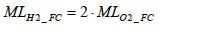 (2)
(2)
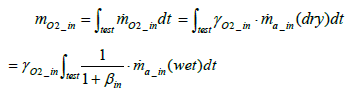
Calculation of intake oxygen amount: The total mass of oxygen fed into the fuel cell stack mO2 _ in during a running test (under a certain driving cycle) is expressed by the following equation:
 (3)
(3)
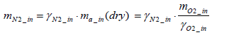
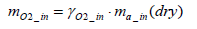
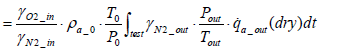
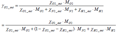
Where the mass fraction of oxygen in intake air γO2_ in is expressed by Equation (4) below.
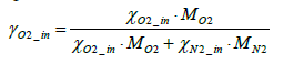 (4)
(4)
The total mass of oxygen fed into the fuel cell stack mO2 _ in is expressed by Equation (5) below in terms of intake air density  and the flow rate of instantaneous intake air
 (dry) :
 (5)
(5)
As the above equation suggests, the value of mO2 _ in can be determined by measuring the amount of intake air flow rate (dry).Nevertheless, the installation of a flowmeter in the intake system would require vehicle modifications which may affect the vehicle’s performance. Moreover, it is preferable to keep measurement items as few as possible in order to minimize total measurement errors. In this paper, therefore, we proposed a method of determine the amount of intake oxygen mO2 _ in via the measurement of only the exhaust flow rate and concentration.
Assuming that nitrogen mass is conserved between inlet and outlet of the fuel cell stack, Equation (6) below stands valid:
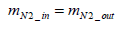 (6)
(6)
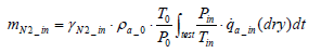
Consequently, the mass of nitrogen intake per test mN2_in (dry ) can be expressed by Equation (7) below.
 (7)
(7)
Then from Equation (5), the following equation holds valid:
 (8)
(8)
On the other hand, the mass of nitrogen exhaust per test mN 2 _ out is expressed as per the following equation:
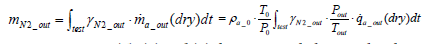 (9)
(9)
From Equations (6), (8) and (9) the equation below can be obtained.
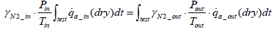 (10)
(10)
Assuming that intake air pressure pin and intake air temperature Tin remain constant during the test period, then Equation (11) below stands:
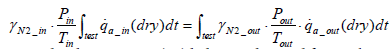 (11)
(11)
Accordingly, Equation (12) below is obtained for intake air volume ma_in(dry ).
 (12)
(12)
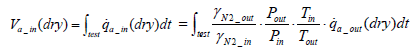
Also the mass of intake air per test ma_in(dry ) can be expressed by Equation (13) below:
 (13)
(13)
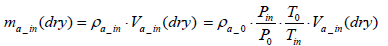
The equation for the mass of intake oxygen mO2 _ in can be substituted as follows:
 (14)
(14)
From the above equation it is clear that the mass of intake oxygen can be derived by measuring the concentration, pressure and flow rate of exhaust gas.
Calculation of oxygen emission amount: The mass of oxygen emissions per test mO2 _ out is expressed by the equation below.
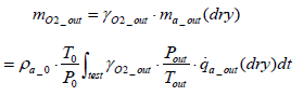 (15)
(15)
Calculation of the amount of hydrogen used for power generation: Assuming the mass of oxygen used by the fuel cell stack for power generation to be mO2 _ in , the following equation is obtained in terms of intake oxygen amount mO2 _ in and emitted oxygen amount 
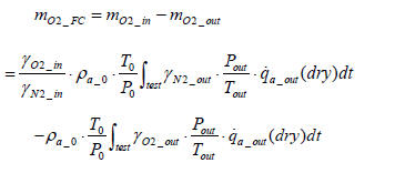 (16)
(16)
Assuming that 
 and that the exhaust gas consists of oxygen, nitrogen and hydrogen, the following equation stands valid:
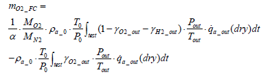 (17)
(17)
Where
 (18)
(18)
Accordingly, the molar number of oxygen MLO2 _ FC consumed through the power generation work of the fuel cell stack can be determined by Equation (19) below.
 (19)
(19)
Thus the molar number of consumed hydrogen mH 2 _ out is obtainable through the multiplication of Equation (19) by 2.
Calculation of hydrogen emission amount: With the oxygen balance method, it is impossible to measure the consumption amount of those hydrogen emissions that have not been involved in the power generation function of the fuel cell stack, such as leaked, cross-over and purged hydrogen. Although varying according to fuel cell designs, operation durations and driving conditions, the proportion of these non-working hydrogen is expected to be reduced by future technological improvements but at present remains an unneglectable factor for accurate fuel consumption measurement. In this study, therefore, we estimated the amount of hydrogen emissions by measuring the exhaust flow rate and hydrogen concentration in exhaust gas, and added the estimated amount of hydrogen emissions to the amount of hydrogen consumed for power generation.
The equation for the mass of hydrogen emissions per test mH 2 _ out is as shown below.
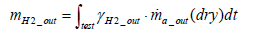
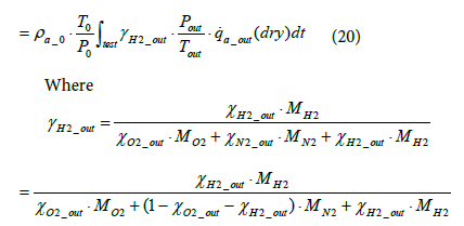 (21)
(21)
The molar number of hydrogen emissions not involved in power generation MLH2 _ out can be derived using Equation (22) below.
 (22)
(22)
The molar number of total hydrogen consumption per test MLH 2 _ total is determined by Equation (23) below.
 (23)
(23)
Correction of time lags in analyses
In the case where the exhaust flow rate and oxygen concentration vary with time, the exhaust flow rate shows the same value anywhere in the exhaust piping provided that the gas compressibility factor is not taken into consideration. Yet exhaust oxygen concentration varies according to the distance from the fuel cell system outlet. Consequently, in applying the oxygen balance method to transient fuel cell operation it is necessary to take account of the response of the gas analysis sampling system. In this study, we reduced time lags in the gas sampling system as much as possible and took the remaining time lag into consideration in conducting calculations.
Since the installation position of the flowmeter on the exhaust piping makes inevitable a delay in the measurement of oxygen concentration, the oxygen flowrate was calculated by assuming a time lag τ as shown in Equation (24), where τ represents the dead time required for the gas emitted from the fuel cell system to reach the flowmeter. The flowrate at the flowmeter position at time t was derived by mathematically integrating the value of time lag Vs under the condition where the integrated value became equal to the pipe volume of the piping section extending from fuel cell system outlet to the flowmeter. Equation (25) shows the relationship between Vs and τ .
 (24)
(24)
 (25)
(25)
Experimental equipment
Using a fuel cell system, an experiment was conducted to evaluate the effect of correcting analysis time lags in the oxygen balance method. The layout and photographic view (measurement setup) of the experiment are shown in Figures 2 and 3, respectively. To assess the measurement accuracy of the oxygen balance method, a hydrogen flowmeter CMS2000 of Yamatake was installed within the hydrogen supply line of the fuel cell system. Developed specially for the FCV hydrogen flow rate method, this flowmeter had been used in many FCV fuel consumption tests and had recorded a relative error of ± 0.5% as compared to the data obtained through the mass and pressure methods, thus proving sufficient accuracy for the evaluation of the oxygen balance method. While the exhaust pipe volume from the fuel cell system outlet to measurement position stood at approximately 19L in the FCV tests conducted in 2007, the exhaust pipe volume was reduced to 9 L and 3 L in this experiment. As a result the time lag in measurement line were slashed down to 1/2~1/6. Additionally, a Pitot flowmeter was installed in the exhaust line of the fuel cell system, and the piping was heated to or above the exhaust temperature to prevent condensation. Immediately downstream of the Pitot flowmeter, a gas sampling line was created for exhaust gas analysis. This sampling line had a branch for capturing room air and for measuring the oxygen concentration of room air before and after each test. As the FCV in its driving operation casts away a small amount of hydrogen to keep a high hydrogen purity inside the fuel cell (hydrogen purge), in our oxygen balance method the hydrogen content in exhaust gas was measured and added to the calculation of hydrogen consumption.

Figure 2: Schematic of oxygen balance method equipment.

Figure 3: Configuration of exhaust measurement setup.
The oxygen analyzer
Because the reported oxygen utilization rates of FCVs are 20% ~ 30%, it would be difficult to make full use of the oxygen analyzer’s dynamic range and high measurement accuracy is demanded for oxygen analyzers. Further, as the oxygen utilization of an FCV varies according to driving conditions, high-level responsiveness is required for oxygen analyzers. In this study, an oxygen analyzer of magneto-pneumatic detection type (MPA-720F model of Horiba) was employed. The error performances of this oxygen analyzer in comparison with standard gas are shown in (Figure 4). Test numbers 2 and 4 gave the smallest error of approximately -1.3% in reading value, but test numbers 1, 3 and 5 recorded larger errors thus pointing to some problems in its linearity, repeatability and drift deviation characteristics. On the other hand the responsiveness tests found a response time of 1.5s covering 10% ~ 90% of all response time. While oxygen analyzers of magneto-pneumatic detection type are known to be slow in their response, this study improved the responsiveness of its oxygen analyzer through the use of small-volume sampling equipment and a modified calculation circuit.

Figure 4: Error of MPD (Magneto-pneumatic detection) oxygen analyzer.
The exhaust flowmeter
Exhaust gas from FCV consists mainly of air emitted from the fuel cell stack’s air electrode (cathode), water via power generation, and purge hydrogen from the fuel cell system. Because the FCV often emits from its tailpipe water from the fuel cell system and condensation water from exhaust piping during its stop and acceleration operations, it is necessary that the flowmeter is mist-resistant and receptive to twophase flow. Also taking into account the characteristics of low pressure loss and pulsating flow responsiveness, we developed a Pitot flowmeter satisfying all the above requirements Equation (26).
Table 1 shows the major specifications of the exhaust flowmeter we developed, (Figure 5) the structure of the flowmeter’s measuring portion, and (Figure 6) the appearance of the exhaust flowmeter. While the flow range varies according to fuel cell system design and running conditions, the maximum flow was set at 3,000 L/min on the basis of driving cycles used in fuel consumption testing. The flow conditions were set at a 60°C temperature, 80% ~ 100% RH humidity, and a working pressure range from atmospheric pressure to tens of kPaG. Additionally the flowmeter’s heat resistance was enhanced considering the heating of the exhaust piping and the exhaust treatment on vehicle side. Based on Bernoulli’s principle, in order to derive the flow speed, the flowmeter was designed to measure the dynamic pressure of exhaust gas from the differential between the full pressure and static pressure in a Pitot tube inserted into the piping. The flowrate was calculated according to Equation (26) below.
| Type | Pitot Tube Flowmeter |
|---|---|
| Measurement range | Low range100L/min to 800L/min |
| High range600L/min to 3000L/min | |
| Accuracy | within ± 1.0% of readings |
| within ±2.0%of readings@ 100 L/minto 200 L/min |
|
| Response | Less than 1.0s (T10-90) |
| Heat-resistant | 100℃ |
| Pressure drop | Less than 10kPa@3000L/min |
Table 1: Specifications of exhaust flow-meter.

Figure 5: Structure of flow measuring part.

Figure 6: Appearance of exhaust flow-meter.
 (26)
(26)
As the differential pressure of the Pitot tube is proportional to the square of flow speed, in the case of a slow flow speed the differential pressure is small and the accuracy of flow speed measurement depends heavily on the accuracy of the manometer. Using differential pressure sensors of different ranges, therefore, the flow rate range was divided into low and high ranges to obtain a sufficient rangeability. While conventional Pitot flowmeters have their full pressure detection holes directed toward upstream, our flowmeter had its detection holes directed toward downstream for the measurement of negative pressures, thus structurally limiting the possibility of the detection holes clogged by the mist and dust contained in the exhaust gas. Additionally, the connecting pipe was given a purging function to carry out purging periodically.
The flow measuring portion incorporated a mesh-type current plate upstream of the Pitot tube in order to average out flowrates inside the piping. Temperature inside the piping was kept high with a heater and heat insulation covers to prevent condensation in the detection portion. Exhaust gas pressure, temperature and humidity were also measured, enabling conversion into flow rates in standard or postdehumidification state.
Effect of pipe volume reduction
We verified the effect of reducing the exhaust pipe volume between exhaust outlet and flowmeter on the improvement of time lags. Figure 7a and 7b shows the real time fuel consumption measurements for exhaust pipe volumes 9 L and 3 L, respectively, each comparing measurements between the oxygen balance method and the hydrogen flow method, the latter method employing a hydrogen flowmeter. In Figure 7b with a smaller exhaust pipe volume, the results obtained by the oxygen balance method more closely approximated the hydrogen consumption waveform recorded by the hydrogen flowmeter, thus confirming that the reduction of exhaust pipe volume is effective in increasing the measurement accuracy of the oxygen balance method.

Figure 7: Improvement of real time fuel consumption data by reducing the volume of gas sampling system and by correcting the time lag in oxygen concentration analysis.
Time correction in oxygen concentration measurement
Figure 7c shows the Figure 7b data modified through the correction of time lags in oxygen concentration measurement. As a result of the time lag correction, the modified data even more closely approximated the hydrogen consumption waveform recorded by the hydrogen flowmeter as compared to Figure 7b, thus confirming the effectiveness of lag time correction in oxygen concentration measurement.
Evaluation under JC08 mode
Figure 8 shows a part (test time from 1,020s to 1,180s) of the hydrogen consumption data obtained by applying a power output load to a fuel cell system according to the JC08 driving cycle under the same conditions as those of Figure 7c. Although failing to exhibit the spikes of hydrogen purges unlike the measurement data obtained by the hydrogen flowmeter, the oxygen balance method demonstrated a high level of overall trackability. Figure 9 shows the errors made by the oxygen balance method as compared to the measurement results of the hydrogen flowmeter where JC08 output loading cycle was repeated 35 times. While in the FCV test of 2007 the oxygen balance method recorded errors of -5% ~ -24%, the errors in this study declined to -3% ~ +1%. The remaining causes of errors may be accountable to the linearity, repeatability and drift deviation characteristics of oxygen analyzers, and improvements in these characteristics are expected to further upgrade the accuracy of hydrogen consumption measurement by the oxygen balance method.

Figure 8: Behavior of fuel consumption measured by oxygen balance method and Flow method during JC08 mode.

Figure 9: Variation in error of oxygen balance method at JC08 mode.
We devised an oxygen balance method for calculating the amount of FCV fuel consumption on the basis of the chemical composition of exhaust gas from its tailpipe. The oxygen balance method gives reliable data comparable with those of other fuel consumption measurement methods without necessitating vehicle modifications. Also we developed an exhaust gas flowmeter, derived the amount of intake air, and examined the applicability of the oxygen balance method using a fuel cell system. As a result its real time fuel consumption measurement characteristics were improved by reducing the volume of the gas sampling system and by correcting the time lag in oxygen concentration analysis.
Additionally the measurement of a fuel cell system’s hydrogen consumption by the oxygen balance method under the JC08 driving cycle gave errors of -3% ~ +1% as compared to the data obtained by a hydrogen flowmeter, thus substantially improving from the error level recorded in 2007.
In the future we will need to upgrade the linearity, repeatability and drift deviation characteristics of oxygen analyzers in order to further advance the measurement accuracy of the oxygen balance method.
We would like to express our appreciations to the new energy and industrial technology development organization (NEDO) of Japan for its support as part of its “hydrogen-based society infrastructure development project”.