Journal of Aeronautics & Aerospace Engineering
Open Access
ISSN: 2168-9792
ISSN: 2168-9792
Research Article - (2015) Volume 4, Issue 1
This study has been given prominence and confirmed by extensive documentation while recent visualizations observed in a wind tunnel have revealed that rectilinear vortex flows from different angles interacting with one another above warheads. My experimental research has indicated the many and very specific series, by visualizations of wisps of smoke trails, of vortex structures of a preferential nature above a warhead where β=68.6°. The positioning of those structures has thus been determined with regard to the application of very general criteria governing the stability of vortex flows. What have also been exposed are the specific aspects of vortex flows together with some comments concerning the bursting of vortices above the warhead. The purpose of this study is to optimize the connection between marine, air and land forms such as sails, the wings of aircraft, cars and trains – and the stability of fluid flows around such forms.
<Keywords: Visualization; Aircraft; Hydro-dynamics; Aerodynamic
θl, m : preferential angle associated with the whole numbers l and m;
l and m: whole numbers such as m>θ and l ≥ m;
β: apex angle;
Co: length of wing;
i: incidence;
Vo: speed of the flow at upstream infinite;
Re: Reynolds number;
α1: the main or interior inter vortex angle for warheads;
α2: the secondary or exterior inter vortex angle for warheads;
ω1: the main or inter vortex angle for warheads or cones;
ω2: the secondary or exterior inter vortex angle for warheads or cones
Quite a considerable number of studies have been carried out to date into delta wings, gothic wings, cones and also into more or less simple slender bodies formed from combinations of such components; the findings have dealt as much with the development of approximate theories [1] as with the definition of models specifying vortex lift by unit area.
Visualisations of hyper lifting vortex structures, mainly those carried out by Werle [2-8], the analysis of pressure and speed fields created by these vortices, with or without their bursting–notably the analysis by Solignac [9-11] provide quite outstanding studies that are the standard works in their fields. Already described fully in such papers as, for example, those by Werle, Solignac and Stahl [2-17], these findings offer today in their entirety a thorough knowledge of the properties of various types of slender bodies. However, given that the character of most of the aspects referred to remains empirical and limited to this or that degree of incidence [2-17] or to a numeric range [18], the way lies open, starting out from experimental data and various factors of analysis [19], for new attempts to be undertaken to examine the fundamental problems related to the position of vortices created by such slender bodies.
A large number of photographic visualisations, concerning vortex flows developed on the upper surface of delta or gothic wings and cones, have been carried out in the laboratory at Valenciennes University (France) [1,20] in such a way as to provide a better understanding of the development and positioning of vortex structures at not only low and mean incidence but also at high incidence. These visualisations have enabled priority to be accorded to the study of examples of the most elementary shaped bodies, i.e. delta and gothic wings. The results obtained in these two cases, and already fully described in previous papers [19,21], may be acknowledged to have remarkable simplicity and consequently convey the fundamental nature of these studies.
The angles between the vortices have been found, under experimental conditions, to have a preferential nature thereby underlining a simple angular characterisation of their positioning relative to single or double vortex torques.
The visualisations in their entirety were carried out within the dimensions of the air tunnel (45 cm×45 cm section) at the Valenciennes University Aerodynamics and Hydro-dynamics laboratory. The vortex systems developed on the upper surface were rendered visible by providing for emissions of wisps of white smoke at the tip of the warhead: these emissions were obtained by injecting oil under pressure through a tube of small diameter and then, by means of an integrated electrical system, vaporising the oil immediately as it left the probe.
The warhead was fixed onto an axis relayed to a cursor graduated from 0° to 360° which enabled the incidence of cone rotation to be varied. The visualisations were captured on photographs and video film which are today stored in the department’s data base.
Geometrical description
The profile under investigation in the wind tunnel is a warhead having an apex angle β=68.6° and a chord Co=240 mm. It is 1 mm thick. 11 and 12=vortex rotation in opposite directions. 1, 2 and 3, VO=speed (Figures 1a and 1b).
Figure 1a: Influence of the impact on the flow around the wing warhead legend.
Figure 1b: Inclination of the warhead wing.
1) Tablecloth horn wrapping around the main vortex from the apex
2) Low secondary winding around vortices in the same direction but opposite to the main vortex
3) Primary separation line and secondary line of separation
4) Areas swept by previous 1-2-3 vortices
5) Partitioning lines within the fluid
6) Allure lines parietal current.
The evolution of the vortex phenomena was traced in terms of that parameter which exerts the greatest influence on them, namely the angle of incidence of the configuration in relation to the flow. The visualisations were carried out at an upstream speed of flow of 3 m/s.
Reminder of the main phenomena taking place at low and mean incidences
incidence=0°: the flow is uniform on the upper side of the warhead. The boundary layer is observed but there is no flow separation as yet.
incidence=5°: the upstream flow skirts around the leading edges of the profile. Three zones become organised into a central zone and two external ones. The hyper lifting vortices, resulting from the separation of the boundary layer, begin to appear as increasingly organised structures.
incidence=8°: the main and secondary vortices are clearly detected and have now become individualised, concentrated and separated from the boundary layer. Visualization of the central zone has shown it to be gradually fading out.
incidence=10°, i=15°, i=20°: the vortices increase in strength. Both the vortex flow and the direction of the rotation of the vortices are clearly seen. The central zone has disappeared. The presence of tertiary vortices is to be noted although they are extremely difficult to visualise. There is no bursting as yet (Figure 2).
Figure 2: View of the upper surface: β=68.6°, i=3°, 41000
incidence=3°, i=5°: the upstream flow skirts around the leading edges of the profile. Three zones become organised: a central zone and two external ones. The hyperlifting vortices resulting from the separation of the boundary layer begin to appear as increasingly organised structures (Figure 3).
Figure 3: View of the upper surface: β=68.6, i=22°, α=45°, 41000
i=25°: the bursting phenomenon makes its appearance. The main vortices commence bursting a long way downstream from the profile: in fact, a more diffused mass of smoke is observed in this zone. The secondary vortices have burst upstream from the trailing edge; as for the tertiary ones, which are difficult to observe because of their positioning at the edge of the boundary layer, it seems that they burst in the area close to the apex and coil around the main and secondary vortices. Once the secondary vortices have burst, they also coil around the main ones. The asymmetry of the bursting point of the main and secondary vortices is to be noted (Figure 4).
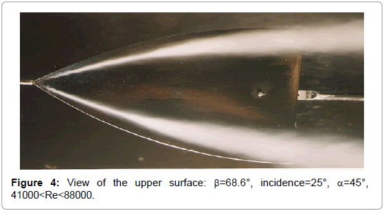
Figure 4: View of the upper surface: β=68.6°, incidence=25°, α=45°, 41000
incidence=40°: the secondary vortices burst near the apex whereas the point of bursting of the main ones has advanced to a third of the way along the chord. A sudden expansion at the core of the main vortices is still discernible, followed by an unstable zone showing quite considerable turbulence (Figure 5).
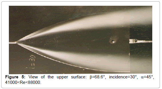
Figure 5: View of the upper surface: β=68.6°, incidence=30°, α=45°, 41000
incidence=30°: the tertiary vortices have now completely disappeared. The secondary ones commence bursting in the area of the trailing edge of the profile (Figure 6).
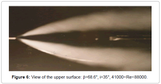
Figure 6: View of the upper surface: β=68.6°, i=35°, 41000
NB: the position of the bursting point is estimated on the basis of a mean reading of the respective bursting points of the right-hand and left-hand main vortices.
incidence=45°: the main vortices break down at the fore quarter of the chord; the secondary ones are absorbed by the main vortices at the apex and are no longer discernible.
incidence=50°: a total bursting of the vortices takes place at the apex. Intense turbulence is observed at about the trailing edge, entailing diffusion of the smoke trail.
Comments
The bursting of the secondary vortices is not as impressive as that of the main ones. In fact, the vortex cores of the latter, after having maintained a cone-shaped form increasing in diameter towards the downstream side, undergo a sudden expansion into a brush-shaped form (the rate of expansion is approximately three to four times the diameter of the vortex core upstream from the bursting point). The point of bursting is immediately followed by a zone in which the flow circulates again and by an area of intense turbulence. The thin wisps of smoke, indicating the main vortices, seem to change direction at the point of bursting and to follow a spiral trajectory downstream.
1. The pulsation phenomenon of the bursting of the vortex has become highly conspicuous from this point in time; the bursting points undergo quite considerable positional fluctuations. The burst vortices seem ″to dance″.
2. On placing an object in the axis of the burst vortices, it can be seen that the bursting points ″rise again″ in an upstream direction but it is also noticed that the bursting point of the secondary vortices is still located upstream from that of the main vortices.
The presence of preferential intervortex angles is observed. The intervortex angles on the warhead are: 10° ≤ ι ≤ 45° ⇒ α1=45°. The experiment has shown the following:
1. A flow on the upper surface of the warhead as regards low incidences;
2. The start of the formation of vortex structures with steadily flowing thin streams becoming separated from each other and heading towards the leading edges;
3. The formation of two vortex systems because the warhead under investigation has a non-preferential apex angle;
4. The deterioration of the systems occasioned by the bursting phenomenon;
5. The unsettling of the profile under investigation on the appearance of the torch phenomenon (i.e. the “cornet-like” spiral coiling of the flow) constituting the disappearance of the intervortex zone.
The exterior secondary system is less significant than, and not so dense, as the core system and is the first one to deteriorate.
The law of filiation is examined between the two systems: the angle of the secondary system is produced from that of the core system (akin to a “father and son” relationship). The bursting evolves in relation to the incidence. It is a function of the apex angle: the greater the apex angle, the sooner the bursting takes place. When the angle of attack increases, the vortices coming from the canard plan evolve closer to the surface of the rear section of the aerofoil wing and towards its exterior. As regard high incidence, the merging process of the two vortex structures begins at about the aerofoil wing: this leads to the fact that no more than one sole vortex structure exists on the surface of the aerofoil wing being the result of the joining of the other two structures (Figure 7).
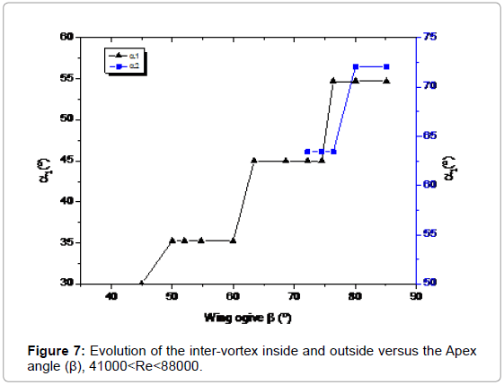
Figure 7: Evolution of the inter-vortex inside and outside versus the Apex angle (β), 41000
The vortex structures close to the warheads’s leading edges
The secondary vortex (II) flows in an opposite direction to that of the main one (I). As the structures are located at the top of the warhead, between S1 and S2, it is very difficult to visualize them by wisps of smoke trails, because their rotational forces, according to Solignac et al. are from 3 to 5 times lower than one of the main vortex (Figure 8).
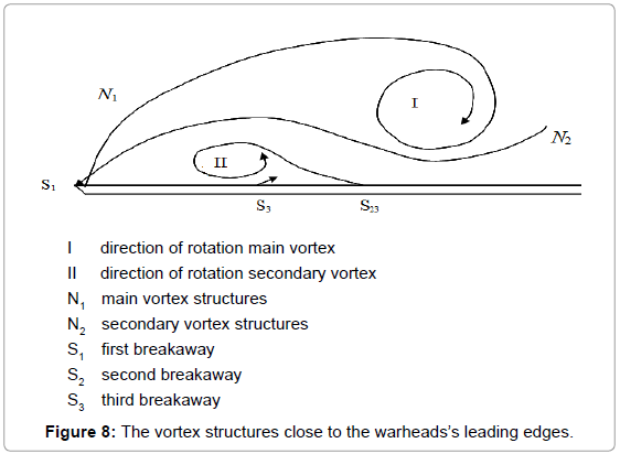
Figure 8: The vortex structures close to the warheads’s leading edges.
Comparison with vortex structures formed on the upper surface of thin gothic wings
The results of the study of the behaviour of vortex structures on the upper surface of gothic wings [13] can be compared with the findings which can be obtained through another examination of the photographs published by Werle [5]. The figures numbered 11a, 11c and 11e in that publication reveal that, for the apex angle β, those structures can easily be calculated from the constituents E (namely, the relationship between the median chord at the edges of the flow and the parabolic shape of the leading edges), each of which being individually and in the order mentioned 37°, 56.4° and 72.1° as indicated by Werle [8].
The progressive evolution from elementary vortices of the sheared flow before bursting towards a particularly stable vortex system, wherein spatial positioning reveals an original organisation, still remains today an enigma. As regards those warhead wings studied, which have included apex angles over a very wide range, the major results from visualisations–the latter made possible by producing smoke streams at the apex of those warheads may be resumed thus :
1. If the angle between the leading edge at their point of intersection (apex angle) β is a preferential one of the first grouping (i.e. 20.7°; 26.6°; 30°; 35.3°; 45°), only two curvilinear vortices are formed and these are to be found above the warhead starting from the apex and thereby constituting a preferential angle between them at the apex point.
2. However, where the apex angle β is either a non-preferential one, or a preferential angle of the second group (i.e. 54.7°; 63.4°), four vortices are observed, the two interior of which form between them a preferential angle α1, while the two exterior vortices form between them another preferential angle α2.
For example, above the warhead having an apex angle β of 52°, the interior vortices create an angle α1 of 35.3° (=θlm: this corresponds with l=m=1) whilst the exterior vortices also create a preferential angle, immediately inferior to the angle β, being an angle α2 of 45° (corresponding with l=m=1). The angle (or angles) between vortices is (or are) constant, either throughout the range of incidences – i.e. from the first appearance of the vortices up to their point of bursting–or at a maximum of two or three levels within the range [13,15].
However, it is important to remember that several of these preferential angles, either separately or in groups of two or three, are equally to be found in the widely accepted standard theories of hydrodynamics and aerodynamics such as those pertaining to the wake of ships and to aerodynamic drag.
One of the central ideas of this present paper is the following: the leading edge of the warhead is at the same time a line along which the borderline layer of flow is especially not very thick and this is because the leading edge is more often than not very close to the bursting point, or to the partitioning line along which the flow is divided between currents on the lower and upper surfaces. On the other hand, this same leading edge is equally a line along which the speed is very high at the boundary of the borderline layer. This is a result of the narrowing of thin fluid streams associated with the sharp curvature of the wall.
A leading edge is therefore a line around which the transverse variation rate of speed is especially high and where, consequently, is to be found a concentration of very high values of the module of the vortex vector whose direction should, in a stationary flow before bursting, coincide with that of the leading edge.