Journal of Physical Chemistry & Biophysics
Open Access
ISSN: 2161-0398
ISSN: 2161-0398
Research Article - (2023)Volume 13, Issue 3
The Young’s double slit experiment and the electron double slit experiment are generally considered to prove the wave nature of light and electrons. The most obvious sign of the double-slit experiment is that there are bright and dark stripes on the screen. However, people have not carefully studied the causes of the light and dark stripes. Here, we demonstrates that the light and dark fringe in Young’s double-slit experiment is not actually the diffraction and interference pattern of light wave, and tries to reveal the real reason for its formation. We have studied the scattering phenomenon of particle flow after passing through the gap, and found that the scattering type and scattering degree of freedom of particle flow are determined by the physical parameters of particles and the gap, and the uniform scattering of particle flow can form a “yes” and “no” discrete distribution pattern on the receiving screen. Based on the “diffraction like” and “interference like” mechanism of particle flow, this paper explains the electron diffraction and interference experiment, as well as the Young’s double-slit interference experiment and the diffraction of light through circular holes and plates. This paper negates the wave-particle duality and the de Broglie material wave hypothesis, fundamentally shaking the foundation of modern quantum mechanics, and has great scientific significance.
Electron diffraction; Double slit interference; Wave-particle duality; Quantum mechanics
In 1905, Einstein put forward the quantum explanation of the photoelectric effect, believing that light has wave-particle duality [1]. In 1923, de Broglie was inspired by this and put forward the material wave hypothesis, believing that all physical particles have volatility [2]. In 1927, Davison and Germer projected a 100 eV electron beam onto the surface of nickel single crystal to observe the scattering of the electron beam. It was found that the scattering beam intensity was discontinuous with the spatial distribution [3]. Almost at the same time, Thomson and Reid penetrated the polycrystalline film with an electron beam with energy of 20 keV, and also observed the discrete characteristics of the scattered electron beam in space distribution [4]. They interpreted the dispersion of the spatial distribution of the electron scattering beam as an electron diffraction phenomenon, similar to the diffraction pattern of light and dark. Therefore, people believe that their experimental results prove that electrons have wave properties, thus confirming de Broglie’s material wave hypothesis.
It is generally believed that since the electron beam can diffract, interference should also occur in theory. Although the electronic double-slit interference experiment is discussed as a fact in many textbooks, in fact, no one has actually done this experiment. As Feynman said, “Never try to do this experiment, because this device must be manufactured on an unimaginable scale” [5]. Until 1961, Jönsson of the University of Tubingen in Germany processed a set of 300 nm wide slits on the copper sheet, and then irradiated them with the 40 keV electron beam of the electron microscope, and finally got the bright and dark stripes similar to those seen by Thomas Young 160 years ago [6]. This bright and dark fringe has become a strong evidence of the interference of the electron beam, which seems to prove once again that the electron has wave property and the correctness of the de Broglie material wave hypothesis. It is generally believed that the electronic double-slit interference experiment has been completed. However, because the light and dark stripes are formed by electron beams, some people think it is difficult to prove whether a single electron also has wave-particle duality. Therefore, people began to challenge the so-called “single-electron double-slit interference experiment” [7-9] and claimed to have realized the single-electron double-slit interference thought experiment conceived by Feynman. They reached the same conclusion, that is, the experiment proved that a single electron has volatility. In 1909, Jeffrey Taylor conducted Young’s double-slit interference experiment with weak light (single photon) [10]. Dirac explained: “Each photon only interferes with itself. Interference will never occur between different photons.” Therefore, many people think that a single electron can also pass through two slits at the same time and interfere with itself.
Obviously, the reason for believing that electrons have volatility is the discovery of so-called electron diffraction and interference phenomena. However, the so-called electron diffraction and interference phenomenon is only the pattern of light and dark. This paper proves that the light and dark fringe in Young’s double-slit experiment is not the diffraction or interference pattern of light wave, so it cannot be considered that the electron has diffraction and interference phenomenon according to the electron beam crystal scattering and the light and dark fringe in the double-slit experiment, and it cannot be proved that the electron has wave motion. The research in this paper shows that the light and dark pattern in the double-slit experiment is the spatial distribution accumulated by the scattering effect of particle flow on the receiving screen after passing through the slit. In this paper, the formation mechanism of Young’s doubleslit experiment, circular hole diffraction and Poisson’s bright spot is explained from the viewpoint of light quantum flow, and the stereotyped cognition that light and dark fringe is diffraction and interference pattern is further denied. Our research shows that physical particles have no wave property at all, the so-called waveparticle duality of physical particles is not established, and the foundation of quantum mechanics is completely shaken.
The light and dark pattern in Young’s double-slit experiment is not the interference pattern of light waves
In Young’s double-slit experiment, the light and dark stripes are interpreted as interference patterns formed by the coherent superposition of waves. This explanation has never been questioned for more than 200 years since Thomas Young, so that people take the light and dark stripes as interference patterns of waves without thinking. People observed the pattern of light and dark when conducting the crystal scattering and double-slit experiment of electrons, so they took it for granted that this is the diffraction and interference phenomenon of electrons, and then believed that the electrons have wave characteristics, thus confirming de Broglie’s material wave hypothesis. However, is the pattern of light and dark in Young’s double-slit experiment really the interference pattern formed by the coherent superposition of waves?
The bright and dark stripes in Young’s double-slit experiment are considered as interference patterns of light waves, mainly because people have compared the bright and dark stripes with the interference patterns of water waves. It is possible to analogize light waves to water waves, but it is wrong to analogize light and dark stripes to interference patterns of water waves.
First of all, the diffraction phenomenon of water waves is that a series of water waves form a new series of water waves after passing through the gap. Therefore, the so-called diffraction pattern of water waves is the wave shape of a new series of water waves. If the light wave is compared with the water wave, the diffraction pattern of a light passing through a single slit should also be the wave shape of a new light wave. However, the wavelength of visible light is only a few hundred nanometres, which can’t be distinguished by human eyes. We can’t see the wave shape of light wave at all. Obviously, the light and dark stripes appearing on the screen after light passes through a single slit are not the diffraction pattern of light.
Secondly, the interference phenomenon of water waves is the coherent superposition of two water waves on the water surface, and the interference pattern that the amplitude increases after the superposition of wave crest and wave crest or wave trough and wave trough, and the amplitude cancels after the superposition of wave crest and wave trough. The interference pattern of water waves is presented on the water surface (we call it the interference surface), which is parallel to the propagation direction of water waves. However, due to the very small wavelength of visible light, we cannot see the wave of light, and the interference pattern of light wave cannot be seen on the interference plane after light passes through the double slit. Obviously, the light and dark stripes seen on the screen perpendicular to the propagation direction of light are not interference patterns of light waves.
Third, the movement of water waves can be seen by the human eye with the help of light, but we cannot observe the movement of light waves with the help of light. Even if the wavelength of light is very long, we can’t see the propagation of light in the vacuum. Only when the light enters the human eye can we feel its bright light. When light travels in the medium, the light propagation path we see is formed by the light scattered by the medium entering the human eye, and we can’t see the wave shape of the light wave on the propagation path. Therefore, even if the light wave interferes, we can’t see the interference pattern of the light wave at all. In the double-slit experiment, the bright lines on the screen are the images formed by the light scattering from the material on the screen and entering our eyes, not the images generated by the superposition of light wave peaks. The dark streak is that there is no light scattering and no light enters our eyes, not because the wave crest and wave trough of the light wave cancel.
Finally, since the light energy will not be offset due to the opposite phase, two beams of coherent light with opposite phase hit the same point on the screen, and the light intensity at that point should be enhanced. It can be seen that the dark stripe interpretation of Young’s double-slit experiment obviously violates the principle of energy conservation and basic experimental facts.
To sum up, the single-slit diffraction of light and the bright and dark fringe in Young’s double-slit experiment are not the diffraction and interference patterns of light. Therefore, the light and dark stripes cannot be used as the basis for wave diffraction and interference.
So how is the light and dark stripes formed? Next, we analyse the mechanism of light and dark stripes produced by particle flow through the gap.
The essence of particles passing through the gap is to interact with the gap
Suppose that the diameter of the particle is D and the width of the gap is d. Only when ≤, the particle can pass through the gap. When particles pass directly through the edge of the gap without collision, their maximum emission angle θ meets cos θ=D/d (Figure 1). Obviously, the smaller the D/d ratio is, the higher the θ value. When the diameter D of the particle is slightly smaller than the width d of the gap, the value of θ is very small (approaching 0 degrees), then the emission angle is slightly greater than 0 degrees, and the particle will collide with the edge of the gap, thus changing the direction of motion of the particle. If the particles have electromagnetic interaction with the material at the edge of the gap, even if there is no direct collision, the close interaction can change the direction of the particles. It can be seen that the gap provides a spatial constraint structure that allows particles to interact with the material at the edge of the gap. When a particle passes through a gap, it is essentially scattering after interacting with the material at the edge of the gap.

Figure 1: Maximum emission angle of particles directly passing through the gap.
Physical parameters of particle flow and gap
Because the essence of particles passing through the gap is that particles interact with the gap to generate scattering, the physical parameters of particle flow and the gap determine the direction and spatial distribution of scattering.
The physical parameters of particle flow include the particle’s material properties (particle type or material composition), shape, size, mass and particle motion speed. In addition, the emission angle and emission mode of particles are also important parameters that determine particle flow. From the quantity of each shot, it can be divided into single particle emission (or point emission) and multi-particle emission (or surface emission); from the perspective of whether the time interval (or frequency) of each launch is fixed, it can be divided into periodic launch and non-periodic launch. Suppose the particle diameter is D and the particle velocity is u. When particles are periodically emitted, the emission frequency is f, that is, the interval between each emission of particles is Δt =1/f . When Δt = D/u , particles are emitted continuously in series one by one, which is called periodic continuous emission; When Δt > D/u , there is a certain distance between the particles emitted before and after, which is called periodic interval emission. When surface emission is performed, particles on the emission surface can be emitted at the same time or not.
The physical parameters of the gap include the shape, size and scale of the gap and the physical properties of the material at the edge of the gap. When people consider the gap, they often only consider its shape and size, ignoring the physical properties of the edge material that forms the gap. In fact, the gap itself is not a physical entity, but the edge material that constitutes the gap.
Scattering degrees of freedom and scattering types of particle flow
The moving particles will change the direction of motion after colliding with the material at the edge of the gap, thus causing scattering. If the same particle collides with the same speed, direction and position of the same gap each time, the direction of motion changed after each collision should be the same. Then the particle flow of the same particle with the same velocity will have a fixed scattering direction as long as it collides with the gap in a fixed direction. If a launching device can launch in a fixed direction, the particle flow it emits will have only one definite particle flow parameter, and only one definite scattering direction after collision with the gap. If the emission device of particle flow is surface emission, then this set of fixed surface emission will form a set of determined particle flow parameters, and there will be a set of determined scattering directions after collision with the gap (Figure 2). If the launching device vibrates regularly during point emission, and the movement direction of particles emitted by point emission changes regularly, then the launching device will form a set of determined particle flow parameters within a certain time. When the particle type and emission device of particle flow are determined, the physical parameters of particle flow are determined; when the gap is determined, its physical parameters are also determined. Obviously, after a group of particle flows that determine physical parameters collide with a slot that determines physical parameters, a group of determined scattering directions will naturally occur. The number of scattering directions of particle flow is called scattering degrees of freedom. The number of scattering directions of particle flow is the number of scattering degrees of freedom. For example, if there are Ns discrete scattering directions in the range of maximum scattering angle α, we can say that the scattering degree of freedom of particle flow is Ns. Therefore, the scattering degree of freedom of particle flow is determined by particle flow parameters and slot parameters. That is to say, as long as the type of particles emitted and the device for emitting particles are selected, and the gap for experiment is selected, the particle flow emitted by the emission device will have a certain degree of scattering freedom after passing through the gap.

Figure 2: A set of determined particle parameters and determined slot parameters determine a set of determined scattering directions.
According to whether the spatial distribution of scattering direction of particle scattering is uniform within a certain range of scattering angle, it can be divided into two types of scattering: Uniform scattering and non-uniform scattering. Combined with the emission types of particle flow, uniform scattering can be classified into the following types: Simultaneous and periodic continuous scattering; Simultaneous and periodic interval scattering; Non-synchronous and periodic scattering; Nonsynchronous and non-periodic scattering.
Diffraction-like and interference-like of particle flow
Regardless of the shape and size of the gap: Assuming that the particle flow hits the gap S in the range of scattering angle α and uniformly scatters, with a total of Ns scattering directions (or scattering degrees of freedom), then uniformly spaced Ns particles will be formed at the receiving screen P. The motion path of particles in the scattering direction is called the scattering path of particles. There are Ns scattering directions, and there are Ns scattering paths. Figure 3A shows the uniform scattering of the particle flow after hitting the gap S. There are four scattering directions in a cross section, and finally the "diffraction like pattern" of four uniformly distributed particles appears on the receiving screen (Figure 3B).
Suppose there are two identical particle uniform scattering sources S1 and S2. When they are close to each other, the particle scattering path will have a crossing point (we call it an interferencelike point). The scattering path is also called the interference-like line. A receiving screen P is set near the interference-like point. The receiving screen will display the interference-like pattern with “yes” and “no” particle distribution, and more particles will accumulate at the interference-like point (Figure 3C).
Obviously, as long as the particle flow undergoes uniform scattering after passing through the gap, the diffraction-like pattern can appear on the receiving screen. If the uniform scattering occurs on the two adjacent slits, the uniform interfacelike pattern can appear on the receiving screen (Figure 3C). If it is non-uniform scattering, a non-uniform interference pattern is formed (Figure 3D).

Figure 3: Scattering type, diffraction and interference pattern of particle flow.
The particle flow will scatter after passing through the gap, and its degree of freedom depends on the physical parameters of the particle flow and the gap. As long as the scattering degree of freedom Ns of the slot is determined, its interference-like pattern can be predicted. Figure 4 shows the interference-like pattern of two uniform scattering sources S1 and S2 with 3, 4, 5 and 6 scattering degrees of freedom, with a maximum of 2, 3, 4 and 5 interference-like points respectively. In other words, the doubleslit interference-like pattern of particle flow is related to Ns, and the maximum number of interference points is Ns-1.

Figure 4: Relationship between scattering degrees of freedom of particle flow and interference points.
Assume that the scattering degrees of freedom of slot S1 and S2 are Ns, and the maximum scattering angle is α. Set the receiving screen at the interference point, and mark it as P1, P2, P3, ..., Pn, mark the interference-like point as fn-k (Figure 5). When the number of interference-like points n on the receiving screen Pn is an odd number, there is a case where the interference-like point is at the center O of the receiving screen, and k=0. The distance between the receiving screen Pn and the double seam is
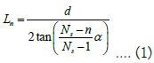

Figure 5: Schematic diagram of particle double-slit scattering interference.
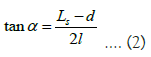
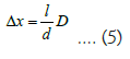
It can be measured that the distance between the receiving screen and the double slit is l, the maximum scattering width of particles on the receiving screen is Ls, and the distance between the two slits is d, then the maximum scattering angle can be obtained from the following formula:
It can be seen that as long as the scattering degrees of freedom Ns, the maximum scattering angle and the double-slit distance d of the slot scattering source are determined, the interferencelike pattern on the receiving screen Pn is determined. In fact, as long as the physical parameters of the experimental device and particles and gaps are determined, the double-slit interferencelike pattern of particle flow is determined. The interference-like pattern on the receiving screen is only related to the distance between the receiving screen and the double-slit.
We first consider the first case: The particle flow hits at the gap and generates uniform, simultaneous and periodic continuous scattering (Figure 6A). Assuming that the two particles emitted from S1 and S2 reach the same position P on the observation screen at the same time, the distance difference between the two particles to the same position is Δr (Figure 6B). From Figure 6C, it can be seen that
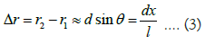

Figure 6: Double slit interference-like of uniformly, simultaneously and periodically emitted particle flow.
Obviously, when Δr is an integral multiple of particle diameter D, that is, Δr=kD (k is a positive integer), the two particles emitted from S1 and S2 reach P at the same time. When Δr=(2k+1) D/2, the time interval between the two particles reaching P is the longest, but the difference is only half a particle. Therefore, the two particles emitted from the two slits will accumulate more particles in the same time as long as they reach the same position (the intersection of particle scattering path), whether they reach the receiving screen at the same time or successively. Where the particle scattering path does not reach, particles will not accumulate on the receiving screen. In this way, in a certain period of time, evenly spaced particle stacks will be formed on the receiving screen. Since the intersection of particle scattering paths is in the middle of the receiving screen, there are more particle stacks in the middle. This is the interference-like pattern of particle double-slit scattering.
It can be obtained from formula (3)
Interval between interference fringes Δx is
The second case is uniform, simultaneous and periodic interval scattering (Figure 6B). Suppose that particles are emitted at a fixed frequency f, that is, the interval between each emission of particles is Δt =1/f . When Δt = D/v , it is obvious that particles are emitted continuously one by one. When Δt > D/v , that is, particles are not close to each other but have a certain interval. Let D' = vΔt , when Δr = kD' , particles from S1 and S2 reach P at the same time. If D’>D, the extension of the emission time interval is equivalent to expanding the particle diameter to D’, which we call “virtual particle diameter”. Therefore, no matter whether the particles are emitted one by one continuously or periodically, the interference-like pattern can be obtained.
The third case is uniform, non-simultaneous and non-periodic scattering. It is assumed that particles have Ns scattering degrees of freedom in the range of scattering angle α. Due to the uniform scattering of particles, the probability of particles reaching Ns positions on the receiving screen after passing through the gap is equal. Therefore, the probability of particles passing through each scattering path is the same regardless of whether particles are emitted at the same time and periodically. It can be seen that in the double-slit experiment with particles, the probability of particles passing through each scattering path is the same as long as the particles are uniformly scattered after passing through the slit. Even if only one particle is emitted at a time, the time interval of each emission is different. After a certain amount of particles are accumulated, a stable interference-like pattern can be formed on the receiving screen. Since S1 and S2 are uniform scattering sources within the range of scattering angle α, the probability of each particle passing through any scattering path after hitting S1 or S2 is 1/Ns. Assuming that the total number of particles scattered by S1 and S2 in the scattering angle range is Nt in T time, the number of particles passing through any scattering path is Nt/Ns. If the interference-like point is on the receiving screen, the number of particles at the interference-like point is 2Nt/Ns. Therefore, on the receiving screen, more particles will be accumulated at the position of the interference-like point, and it can be seen from Figure 5 that the central position of the receiving screen presents a clearer band.
The fourth case is non-uniform scattering. This situation can be divided into two types, one is deterministic non-uniform scattering, and the other is nondeterministic non-uniform scattering. Deterministic non-uniform scattering means that the spatial distribution of the scattering path is uneven, but the scattering path is determined. This kind of scattering source can also produce double-slit interference pattern due to the existence of certain scattering path, but the strip distribution is uneven. Non-deterministic non-uniform scattering refers to the uneven spatial distribution of the scattering path. The scattering of particles rarely has the same scattering path, and the particles passing through different scattering paths are also random. This kind of nondeterministic non-uniform scattering can be considered as random scattering with infinite scattering degrees of freedom. In general, it is difficult to obtain a stable doubleslit interference pattern. However, complete randomness rarely occurs.
When the gap is rectangular square hole: Assume that the gap is rectangular and the length is ‘a’ and the width is ‘b’. The particle flow is surface emission, and it is periodic continuous emission. The uniform, simultaneous and periodic continuous scattering occurs at the gap. The scattering path is a trapezoidal platform, and the scattering angle is α, the lateral divergence angle of each trapezoidal platform is θ, the longitudinal divergence angle is β. The scattering degree of freedom of the slot is Ns. The distance between the receiving screen and the gap is l. Then, the area of the “strip” displayed on the receiving screen is (Figure 7):
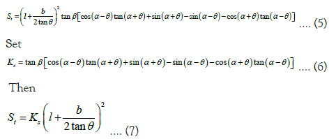

Figure 7: Particle flow diffraction pattern and schematic diagram of rectangular slot.
When the material and size of the gap and the particle flow are determined, the divergence angle α and β of the scattering path (trapezoidal platform), the scattering degree of freedom Ns and the maximum scattering angle are determined. When calculating the area of each strip on the receiving screen, the Ks value is only related to the scattering angle α of the scattering path corresponding to the strip. The larger the scattering angle α, the greater the Ks value. When the distance l between the receiving screen and the slot is fixed, the band area St increases with the increase of the scattering angle α. Assuming that the number of particles passing through the slot S per unit time is N, the number of particles in each strip on the receiving screen is N/ Ns. Then the particle density of each strip on the receiving screen per unit time is:
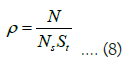
Obviously, the larger the scattering angle α of the strip, that is, the farther away from the central strip position O, the larger the area of the strip St, and the smaller the particle density ρ of each strip on the receiving screen per unit time.
When two identical rectangular slots S1 and S2 are used for the double-slit experiment, the number of particles received per unit time on the “strip” of the interference-like point is 2N/Ns, while the quasi-interference point is concentrated in the middle of the receiving screen, the “strip” area St is smaller, the number of particles received per unit time is more, the particle density is greater, and the middle “strip” of the interference-like pattern is more obvious.
Diffraction and interference of light
We have previously proved that the bright and dark stripes in Young’s double-slit interference experiment are not interference patterns of light waves. So how is the light and dark stripes formed?
According to the classical electromagnetic theory, light is an electromagnetic wave. According to our latest research, an electromagnetic wave with an electromagnetic oscillation period or a wavelength is an optical quantum, and its energy is ε (numerically equal to Planck constant h) [11,12]. Each photon is an independent energy unit, just as a particle has a certain amount of energy. Therefore, a beam of light can be regarded as a beam of light quantum flow moving at the speed of light. In this way, the light intensity can be expressed as the number of photons received per unit area per unit time. Therefore, when two beams of light hit the same place, the light intensity will increase with the increase of the number of photons. Even if the phase of the two beams of light is opposite, although the amplitude of the electromagnetic wave is offset, the electromagnetic energy will not be offset, the quantum of light will not disappear, the light intensity is doubled, and will not become dark. Therefore, in Young’s double-slit interference, the bright fringe is the place where the light quantum reaches, while the dark fringe is the place where the light quantum does not reach. It can be seen that light is regarded as light quantum flow, and the so-called diffraction and interference phenomenon of light should essentially be the diffraction and interference like phenomenon of light quantum flow after uniform scattering through the gap. In fact, Taylor’s weak light double-slit interference experiment proved that the light and dark stripes are formed by the gradual exposure of light quanta on the photographic film [10]. Some studies have found that when ultra-black materials are used for laser diffraction experiments, only one bright stripe appears on the fluorescent screen, and the usual light and dark stripes disappear (Yang Facheng, private communication). This experimental result shows that if the light quantum is completely absorbed by the material at the edge of the gap, there is no scattering effect of the light quantum flow, and the light and dark stripes disappear.
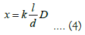
Double slit interference of light: If light is regarded as a quantum flow of light, then the monochromatic light passing through the gap or barrier conforms to the uniform, simultaneous, periodic continuous scattering of the particle flow (Figure 6). Without considering the size of the gap, the wavelength λ of the light wave is regarded as the diameter D of the particle, which is replaced by the formula (4) (5), i.e. the position x and the spacing of the interference fringe Δx:
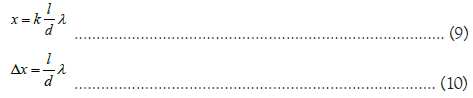
This is the same as the result obtained in the current textbooks. It can be seen that in the light diffraction and Young’s doubleslit experiment, the light and dark diffraction and interference patterns we see on the fluorescent screen are not actually the diffraction and interference patterns generated by light as an electromagnetic wave, but the “diffraction and interference like” patterns of light quantum flow.
If the gap is rectangular, suppose that the light intensity hit on the gap is I0, the frequency of the light is v, there are n beams of light with the same frequency passing through the gap with an area of S0, the total light quantum number passing through the gap is N0, the scattering degree of freedom of the gap is Ns, and the light quantum density of the bright lines on the fluorescent screen is given by formula (8). Because the energy of a photon is ε [11]. Therefore, the light intensity Ik of the k-th bright line on the fluorescent screen Pn is:
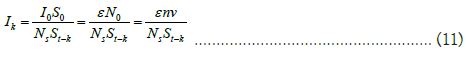
Where, St-k is the area of the k-th bright line on the fluorescent screen Pn:
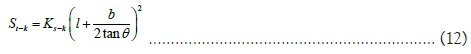
Ks-k is the Ks value of the k-th bright line on the fluorescent screen Pn:

With the increase of k, that is, the farther the bright line is from the central bright line, the larger Ks-k is, the larger the bright line area St-k is, and the smaller the light intensity Ik is, which is why the diffraction line of light is the brightest in the central bright line, and the brighter the light is on both sides.
When the “double slit interference” of light occurs, the light intensity on the “interference like point” is the “superposition” of the light intensity on the “diffraction like” pattern of two rectangular slits, so the light intensity on the “interference like point” near the central bright spot is greater. Because of the uniform scattering in the range of scattering angle, the light intensity of the interference-like point is twice that of the noninterference- like point.
Diffraction of light from circular hole and circular plate: When the gap is a circular hole, the two points where each section perpendicular to the circular hole intersects on the circular hole are equivalent to the two slits S1 and S2 of the particle flow double-slit experiment (see Figure 4). Obviously, when the gap is a circular hole, it is equivalent to countless double seams forming a ring. If the particle flow is evenly scattered on the wall of the circular hole, a concentric ring of particles with “yes” and “no” will appear on the receiving screen. If the interference-like point is at the center O, a central bright spot will be formed. If it is uniform scattering and there are Ns scattering degrees of freedom, then Ns-1 concentric rings will appear (Figure 8).

Figure 8: Diffraction pattern and schematic diagram of particle flow circular hole.
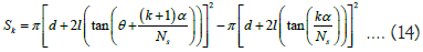
Assuming that the light intensity of the circular hole wall irradiated by light is I0, the thickness of the circular hole wall irradiated is d, and the circular hole wall is a ring with a width of d, then the width of the ring on the fluorescent screen is d ‘=d+2ltan θ. Assume that the ring scattering angle is θ, the ring scattering degree of freedom is Ns, and the maximum scattering angle is α, then the area of the concentric ring from inside to outside is Sk:
The light intensity of the ring is
The larger the k, the larger the Sk area, that is, the area of the outer concentric ring is larger than the area of the inner ring, the smaller the light intensity Ik of the ring, which can explain that the more outward the ring flare is, the darker the brightness is.
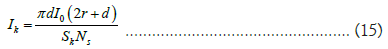
Assuming the radius of the circular hole is r, the maximum angle of light after directly passing through the circular hole is β,then the radius of the circular spot formed in the center of the fluorescent screen is R = r + 2l tanβ ,the area is π( r + 2l tanβ)2 . Assuming that the light intensity directly passing through the circular hole is I0, the light intensity of the circular spot on the fluorescent screen is
If the circular light spot formed by the circular hole wall scattering is within the circular light spot, the light intensity of the circular light spot shall be added to the light intensity of the circular light spot. Therefore, circular light spots are often bright.
The ratio of circumference to area of circular hole is C/S = 2 r . The smaller the radius r is, the larger the C/S ratio is, which means that the more particles that pass through the circular hole and interact with the edge of the circular hole to produce scattering, and the more obvious the diffraction-like phenomenon is in a certain time; On the contrary, more particles directly pass through the circular hole, less scattering particles, and the diffraction like phenomenon is not obvious within a certain time. Therefore, when light is diffracted by a circular hole, the smaller the radius of the circular hole is, the more obvious the diffraction pattern of the circular hole is. When the radius of the circular hole is large to a certain extent, it is not obvious.
The circular plate diffraction of light is similar to the circular hole diffraction. The difference is that the light is blocked by a circular plate and cannot hit the receiving screen, while a circular shadow is formed on the fluorescent screen (Figure 9). Because the circular aperture diffraction time forms a bright circular spot on the fluorescent screen through the circular aperture, it cannot be observed that the interference point forms a central bright spot at the central O. If it is a circular plate diffraction, because the center of the fluorescent screen is just a circular shadow, the concentric halo and the central bright spot can be observed. This central bright spot is called Poisson’s bright spot. In fact, with the movement of the phosphor screen Pn, the interference-like points at the center O of the phosphor screen appear alternately. This can explain that the so-called Poisson bright spots appear alternately with the moving of the fluorescent screen, and concentric halos appear in the shadow.

Figure 9: Circular plate diffraction-Poisson bright spot.
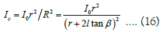
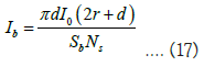
When the light shines on an opaque circular plate obstacle, like circular hole diffraction, the circular plate diffraction will also appear on the fluorescent screen with bright and dark concentric rings. These bright and dark rings can also be seen in the shadow of the circular plate. The light intensity of the bright rings can be calculated according to formula (16). If the interference-like point is at the center O of the fluorescent screen, the so-called “Poisson spot” will appear. If the area of Poisson’s spot is Sb, the light intensity of Poisson’s spot is:
The results of electron beam scattering experiments by Davidson and Gamer et al. [3] found that the scattering beam intensity was discontinuous or discrete with the spatial distribution, and the results of the electron double-slit experiment by Jönsson, et al. [6], showed light and dark stripes, which were interpreted as electron diffraction and interference phenomena. However, we have proved that the light and dark interphase fringe in Young’s double-slit experiment is not the diffraction and interference pattern of light waves, so we cannot judge the existence of diffraction or interference phenomenon of electrons based on the light and dark interphase fringe. This paper reveals that the essence of particle flow through the gap is that particles collide (interact) with the material at the edge of the gap to produce scattering. The physical parameters of particles and slots determine the spatial distribution of scattering direction and scattering degree of freedom of particle flow. As long as the experimental device is determined and the physical parameters of particles and gaps are determined, the determined light and dark patterns can be obtained on the receiving screen at a specific distance. The particle flow diffraction and interference like mechanism explained in this paper can not only explain the socalled diffraction and interference phenomena of electrons, but also explain the diffraction and interference phenomena of light, including the famous Young’s double-slit experiment, circular hole diffraction and Poisson’s bright spot.
Since the “light and dark fringe” is not the diffraction and interference pattern of light waves, the results of the electron beam double-slit experiment by Jönsson, et al. [6], cannot prove that the electron has volatility, so it is obviously meaningless for Tonomura, et al. [7], and Bach, et al. [8], to attempt to use the “single electron double-slit interference experiment” to obtain the light and dark fringe to prove that a single electron has “volatility”. In fact, they made a film of the experimental process, which clearly showed that a single electron hit the screen like a random white dot. With the continuous emission of electrons, more and more electrons are detected on the receiving screen, and the pattern of light and dark gradually emerges. The experiment lasted for 20 minutes [7], or 2 hours [8]. It can be seen that if only one electron is emitted, only one white spot can appear on the receiving screen, and the light and dark stripes cannot be formed at all. The bright and dark pattern on the receiving screen is formed by the accumulation of white dots formed by countless electrons hitting on it. Obviously, this experimental result just proves that a single electron is a particle rather than a wave, and it is impossible to draw the absurd conclusion that a single electron has volatility and interferes with itself. The research in this paper is of great significance for correcting people’s wrong understanding.
Electron diffraction and interference experiments are believed to confirm de Broglie’s material wave hypothesis. However, the research in this paper shows that the so-called electron diffraction and interference experiments are wrong interpretations of the patterns of light and dark, so the hypothesis that the material wave hypothesis is confirmed is not true. Based on the basic concepts of particle and wave, Einstein’s view of wave-particle duality of light is not rigorous, or it is a literary rhetoric rather than a scientific language, because its so-called light-particle nature is only a metaphor to describe the characteristics of its instantaneous and electronic interaction, and light is not a real physical particle. When de Broglie proposed the wave-particle duality of physical particles, the so-called wave-particle duality of physical particles was not a wave in the real physical sense, but an imaginary nonmaterial wave (phase wave) [2]. Therefore, the so-called wave-particle duality is not a scientific term in the strict sense. It cannot describe the physical particle is also a wave, or the wave is also a particle. Based on the basic logic, since the imaginary nonmaterial wave (phase wave) proposed by de Broglie is not a wave in the physical sense, diffraction and interference phenomena cannot occur. Therefore, the so-called electron diffraction and double-slit interference experiments have errors in physical interpretation.
Schrodinger established Schrodinger equation [13], on the basis of de Broglie’s phase wave hypothesis. In order to explain the physical meaning of wave function, he changed de Broglie’s “phase wave” to “matter wave”. Since then, de Broglie’s theory has also been called the theory of matter waves. However, the concept of matter wave itself is self-contradictory, because this socalled “wave” is actually de Broglie’s imaginary non-physical wave, which is not a real physical wave but a mathematical “wave”. In addition, Born put forward the interpretation of probability wave of wave function, and probability wave is a wave in mathematical sense, not a wave in real physical sense. Therefore, the foundation of the establishment of quantum mechanics is not the objective physical reality, but a mathematical model based on the analogy of “wave-particle duality”. Its various interpretations obviously fail to conform to the physical reality and often violate the common sense and logic, which has brought a lot of confusion to people. Einstein insisted that quantum mechanics was incomplete. Bohr said, “If anyone is not confused by quantum theory, he does not understand quantum mechanics at all”. Feynman admits that no one understands quantum mechanics. He said that electronic interference is the core of quantum mechanics, which contains the only mystery of quantum mechanics [5]. Doubleslit interference is considered to be the cornerstone of quantum mechanics, because it is considered to clarify the key features of quantum mechanics: Interference and wave-particle duality of matter [8]. However, our research shows that the light and dark fringe in the “double slit interference experiment” of particles such as light and electron is not the interference pattern of wave, but the interference-like pattern of particle flow. In fact, the diffraction-like and interference-like mechanism of particle flow can not only explain the Young’s double-slit interference and electronic double-slit interference experiments, but also explain the so-called diffraction and interference experiments made with any other particles, such as the diffraction and double-slit interference experiments made by neutrons [14], atoms [15,16], C60 [17], 810 organic macromolecules [18], and even bacteria [19,20]. These experiments were erroneously believed to prove de Broglie’s theory of matter waves, and now they have just become strong evidence to deny it.
Through the study of the diffraction-like and interference-like mechanism of particle flow, we found that the light and dark fringe in the double-slit interference experiment is formed by the uniform scattering of particle flow through the gap, not the diffraction or interference pattern of the wave. Therefore, it is proved that the physical particle does not have wave property, the so-called wave-particle duality of the physical particle is not established, and the foundation of quantum mechanics is completely shaken.
[Crossref] [Google Scholar] [PubMed]
[Crossref] [Google Scholar] [PubMed]
[Crossref] [Google Scholar] [PubMed]
[Crossref] [Google Scholar] [PubMed]
Citation: Zeng J, Zeng T (2023) Study on the Diffraction-Like and Interference-Like Mechanisms of Particle Flow. J Phys Chem Biophys. 13:351.
Received: 19-Apr-2023, Manuscript No. JPCB-23-23611; Editor assigned: 21-Apr-2023, Pre QC No. JPCB-23-23611 (PQ); Reviewed: 05-May-2023, QC No. JPCB-23-23611; Revised: 12-May-2023, Manuscript No. JPCB-23-23611 (R); Published: 19-May-2023 , DOI: 10.35248/2161-0398.23.13.351
Copyright: © 2023 Zeng J, et al. This is an open-access article distributed under the terms of the Creative Commons Attribution License, which permits unrestricted use, distribution, and reproduction in any medium, provided the original author and source are credited.