Journal of Aeronautics & Aerospace Engineering
Open Access
ISSN: 2168-9792
ISSN: 2168-9792
Research Article - (2015) Volume 4, Issue 1
The airline industry has been marked by numerous incidents. One of the first, who accompanied the start of operation of the first airliners with jet engines, was directly related to the portholes. Indeed, the banal form of the windows was the source of stress concentrations, which combined with the appearance of micro cracks, caused the explosion in flight of the unit. Since that time, all aircraft openings receive special attention in order to control and reduce their impact on the aircraft structure. In this paper we focus on the representation and quantification of stress concentrations at the windows of a regional jet flying at 40000 feet. To do this, we use a numerical method, similar to what is done at major aircraft manufacturers. The Patran/Nastran software will be used the finite element software to complete our goals.
<Keywords: Aircraft; Bay; Modeling; Portholes; Fuselage; Pressurization; Loads
There are some methods to realize the appearance of additional expenses at the window. The calculation by finite element is one of the main methods used [1], particularly by aircraft manufacturers in the interests of economy, speed and reliability [2]. This case will have to obtain internal loads and levels constraints from well-defined external loads [3-6]. To do this, Figure 1 shows the process of generating internal loads. Thus, the action plan is shown in the following figure.
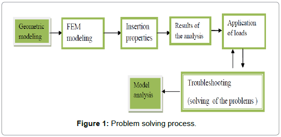
Figure 1: Problem solving process.
To do this, we will use the calculation by finite element software Patran/Nastran, which is considered standard in the aerospace industry and is used in all major aerospace companies [7]. The launch into the heart of this paper will be done after an upgrade on the operation of this software. Geometric modeling is the most important step in the process of degeneration of internal forces, to the extent that it serves as support for the creation of the finite element mesh [8]. Thus, our body is composed of frames, stiffeners, coating and finally the floor. The stiffeners support larger primary times, resume compressiontension efforts, and are guarantor of the overall stiffness. Frames give the external shape of the fuselage and support, in large part, the circumferential stress upon pressurization. The coating shows a part of shear efforts then distributes to the stiffeners, which in turn transfer them to the frames. The floor, meanwhile, adds to the rigidity on the transverse and longitudinal planes [9-12]. Table 1 below summarizes all the geometric data used for modeling.
| Objet | Value |
| Diameter | 96 in |
| Distancebetween the floor andthe fuselage | 79,8 in |
| Framelocation | 16 in |
| Overalllength | 112 in |
| Number ofwindowframes | 1 |
| Number ofstringers | 54 |
Table 1: Geometric Data
The issue is part of a structural analysis context. Indeed, aircraft are subjected to various loads and load cases during their flight cycles. Then there exists in each flight phase, one, or even several cases of loading. It is then necessary to situate our study, Phase flight on which you will base our analysis. In our case, we focus on the “cruise” phase of a commercial flight. During this phase of flight several loading cases may exist depending on the portion to be analyzed on the aircraft. In our case, we will analyze the fuselage. A major case of loading in the fuselage pressurization. This usually occurs in the cabin given its importance to the survival of the passengers, at high altitude. Indeed, taking the altitude the air is thinner and lower atmospheric pressure gradually. It is then necessary to pressurize the cabin to the survival and passenger comfort. However this pressurization is not beneficial to the structure as it involves additional structural loads. The first airliner to experience the consequences of these additional expenses is the Dehavilland Comet 1. This aircraft was the first commercial aircraft to fly with jet engines, allowing pressurization of the unit. However, the first version of this unit possessed rectangular windows, which were the cause of many accidents. Indeed, the banal form of the windows was the stress concentration source combined with the appearance of micro cracks caused the explosion in flight of the unit.
The windows, like other openings in an aircraft when receive special attention. Among the openings, gates, baggage doors, cut-out for kerosene tanks, or openings for antennas, etc., are all sensitive parts on aircraft.
In this project we focus on the representation and quantification of stress concentrations at the windows of the aircraft flying at 40,000 feet above sea level. It should be noted that during the initial presentation of the project, the subject referred to “openings” in their globalities. Given the impossibility of treating all types of possible openings for this project, I chose to restrict and deepen my study of the case of the portholes. We will analyze first place pressurization and now and then twisting the fuselage.
The objective is to achieve the most important two stages namely obtaining a finite element model of integrity, and the calculation of internal forces as shown in the examples in the Figures 2 and 3.
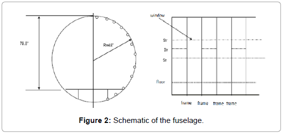
Figure 2: Schematic of the fuselage.
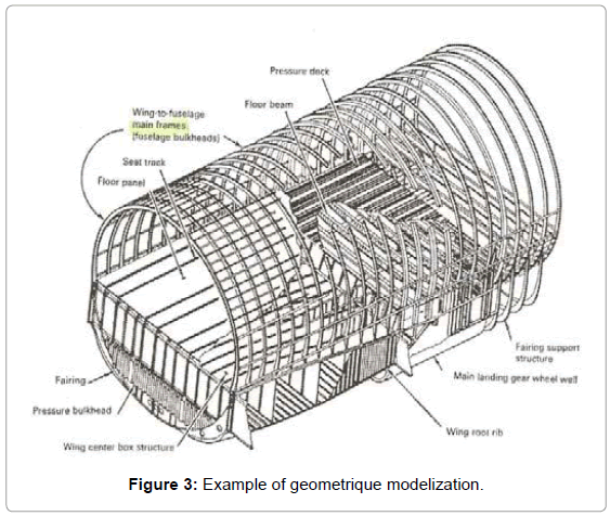
Figure 3: Example of geometrique modelization.
As stated previously, the modeling by finite element based on the geometry, to be defined. Due to the CQUAD4 surfaces elements are obtained and through the curves, CROD elements. The frames are made of soles, modeled by CROD elements, and their soul is modeled with CQUAD4 elements, their normal pointing backwards to ensure consistent results. The stiffeners are modeled by CROD elements, the coating of CQUAD4 elements. Normal of these elements should always point outwards from the cabin. The floor beams are made of soles and souls. The soles are then modeled by CROD elements and the core elements by CQUAD4 with their normal pointing backward or outside of the aircraft. As regards the properties of the elements, the coating is made of aluminum alloy Al 2024-T3 having a thickness of 0.06 ‘’, the frames are Al 7475-T7351 (with a thickness of 0.06 ‘’ for CQUAD and an area of 0.2508 in2 for ROD) along the floor (with a thickness of 0.1 ‘’ and for CQUAD 0.51in2 area for ROD). Finally the stiffeners are made by 2024-T62 (0.1272 in2 for the area) to those of the upper crown of the fuselage and Al 7475-T7351 for those of the lower crown (0.1676 in2 for the area). Regarding the portholes thereof are in fact methyl polymethanecrylate (PMMA or Perspex with 0.02” thick).
The fuselage will be subject to pressurization loads firstly, then torque secondly. We are part of a cruise context to 40,000 feet, and we assume the cabin altitude of 6,000 feet. Thus, a closed cylinder pressurization in induces the appearance of a circumferential stress (hoop stress σH) and longitudinal (σL) as shown in Figure 4.
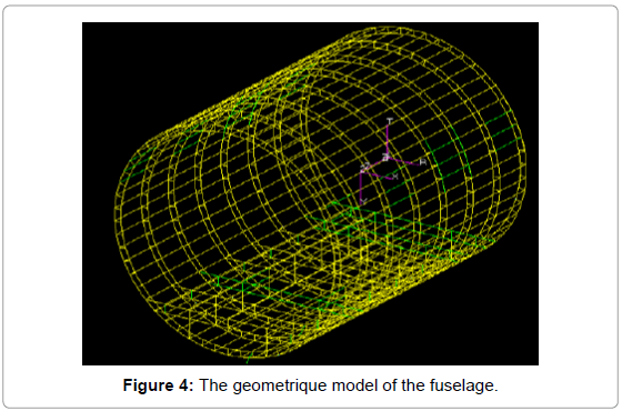
Figure 4: The geometrique model of the fuselage.
To represent the loading on the finite element model, we have to manually apply the longitudinal stress, through MPC, because our body is not closed. This σL stress is 3624 psi and strength associated 65578,359 lbs. An internal pressurization 9.06 psi is then applied to all the plates of the covering. The results speak for themselves. Regarding the stiffeners, we note that height openings in a baie without openings, they do not include any load, their presence in this area is therefore virtually useless. By against the stiffeners located immediately above and below the openings experimenting stress concentration factors of up to 1.56. For managers we can say that the plates are at the openings, the top of the fuselage and about at the floor, undergo an increase in internal stress with a stress concentration factor of up to 1.29. In addition, it appears that top plates immediately resumes lower fewer loads (Figure 5).
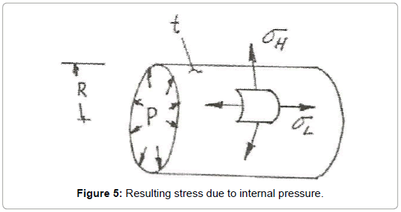
Figure 5: Resulting stress due to internal pressure.
Geometric modeling
Firstly revisit the structure of a fuselage. Airliner fuselages are very similar. The type of the most commonly used structure is the semimonocoque, that is to say, an enhanced cell. The semi-monocoque structure is effective for its weight compared to its rigidity. It allows among other things, to tolerate a crack avoiding the whole structure is affected by the redistribution of loads in other members. Thus, partitions (bulkheads), frames, stiffeners (stringers) and spars are regularly used to give support to the structure. Figure 6 highlights the set of these components.
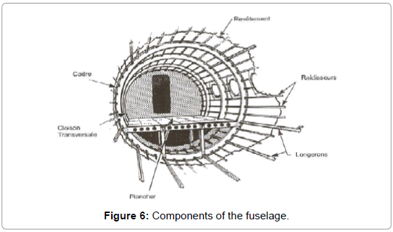
Figure 6: Components of the fuselage.
The rails placed lengthwise, bear the brunt of the primary bending loads (bending moment). Stiffeners show the compression tension forces along the rails, and are guarantees the overall stiffness. Management sets the external form to the fuselage and largely repeats the circumferential stress during pressurization. The coating bears part of shear efforts and distributes them to the stringers which in turn transfer them to the frames. The floor in turn adds to the rigidity of the transverse and longitudinal planes.
Finally the transverse walls are of “plug” at the front and rear of the pressurized section and are located at places subject to larger stresses (location engine, wing roots of the wings, landing gear, etc.) [5]. for this study we model almost all the components of a conventional fuselage except for longitudinal and transverse bulkheads (because we have no large loads on the fuselage). The choice not to model the beams from the fact that all the geometric information needed to model the structure come from aircraft models, and that they do not use rails for their regional aircraft. In fact every time efforts are then taken up by the stringers.
We define the word ‘bay’ all items between two frames. The purpose of this study is to find the distribution of stresses at the windows, so we better model several bay, to obtain a faithful model that either disturbed by the boundary conditions. A choice of seven (7) bays seems so sensible. Thus Table 1 summarizes all the geometric data used for modeling. On Patran we obtain a suitable cross-section of the fuselage, as well as our seven bays desired (Figure 7).
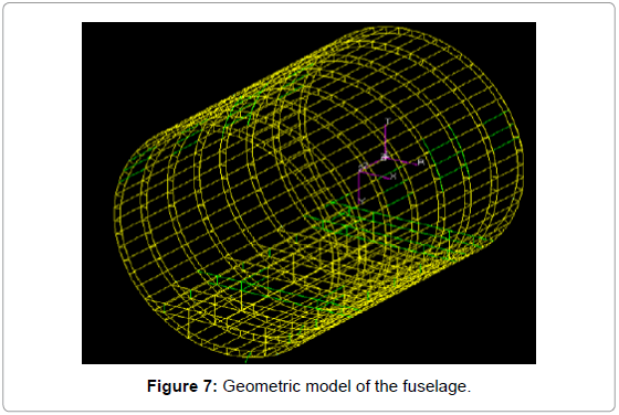
Figure 7: Geometric model of the fuselage.
Finite element modeling
Now the geometric model is completed, it is time to create the finite element model; this model is based on the geometric structure to generate the information necessary for the resolution of the problem. To do this, we have several types of elements used in the construction of a global finite element model of an airplane. Table 2 describes these types of items.
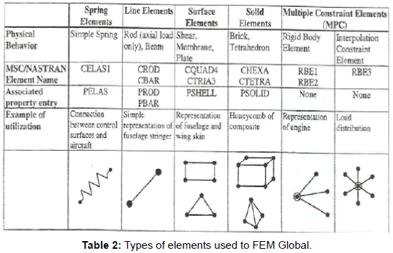
Table 2: Types of elements used to FEM Global.
The frames are made of soles, modeled by CROD elements, and their soul is modeled with CQUAD4 elements, their normal pointing backwards to ensure consistent results. The stiffeners are modeled by CROD elements, the coating of CQUAD4 elements. Normal of these elements should always point outwards from the cabin. The floor beams are made of soles and souls. The soles are then modeled by CROD elements and soul by CQUAD4 elements with their normal pointing backward or out of the plane. The next step would be the mesh. However, before creating the mesh, we must control the way of subdividing the geometric elements like surfaces and curves. For this, we use the ‘Mesh Seed’. Since our geometric model is detailed enough, we just need to do a subdivision for all components.
We can now mesh the model: mesh curves CROD elements and elements CQUAD surfaces. We note that for the representation of portholes we remove CROD elements stiffeners#10, 11, and 12 on either side of the fuselage. We obtain the finite element model (Figure 8).
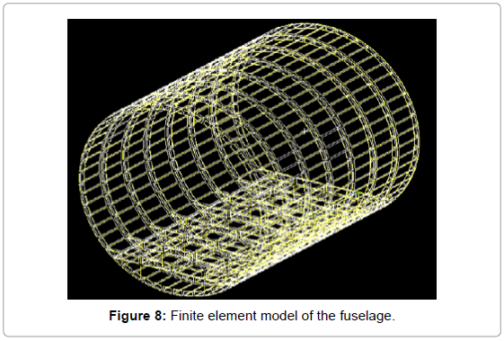
Figure 8: Finite element model of the fuselage.
Setting properties
The definition of property covers of all the elements that we just created. Indeed, it is essential to combine these elements of geometric and material properties. The coating is made of aluminum alloy Al 2024-T3 with a thickness of 0.06 ‘’, the frames are Al 7475-T7351 (with a thickness of 0.06 ‘’ for CQUAD4 and an area of 0.2508 in2 for CROD) as well as the floor (with a thickness of 0.1 ‘’ and for CQUAD4 0.51 in 2 area for CROD). Finally the stiffeners are in 2024-T62 (0.1272 in 2 for the area) to those of the upper crown of the fuselage and Al 7475 T7351 for those of the lower crown (0.1676 in 2 for the area). Regarding the portholes thereof are in fact methyl polymethanecrylate (PMMA or Perspex with 0.02 “thick).
Definition of loadings
As previously announced the fuselage will be subject to pressurization loads first, then when and torsion second. Indeed, we are part of a cruise flight at 40,000 feet context, and we assume the cabin altitude of 6,000 feet. And atmospheric pressure to 40,000 foot being of 2.72 psi and the 6000 foot being of 11.78 psi, then we obtain an internal pressurization 9.06psi cabin. This case of loading in a closed cylinder induces the appearance of a circumferential stress (hoop stress σH) and longitudinal (σL) as shown in Figure 9.
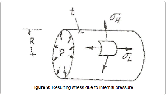
Figure 9: Resulting stress due to internal pressure.
The longitudinal stress is calculated according to the formula [12]
 [12]
[12]
And the longitudinal force exerted on the surface is expressed. With t being the thickness of the coating and r is the radius of the cylinder, it can be deduced that; σL=3624 psi and FL=65578,359 lb.
Things are slightly different for the circumferential stress. Indeed if the body was not made up of reinforcements (frames and stiffeners) equation of this constraint would be
[12]
So we get σ = 6565.83 psi instead of 7248 psi without reinforcement. To represent as closely loading into Patran, then we must apply the longitudinal force on the nodes of both ends of the fuselage, and the internal cabin pressure is 9.06 psi. For not applying the longitudinal stress at each node, we create a RBE3 element connecting each end of the fuselage, taking as the central node depending on each end of the fuselage, and the independent nodes are all other nodes to devices both ends. Finally, we can apply the force dependent node for transmission to turn to independent nodes. We choose to allow all the translations and rotations of the dependent node, while the rotations are blocked for independent nodes because our focus righteous in their translations (all in the global coordinate system). As regards the internal pressure, it is applied to each of the coating panel (Figure 10).
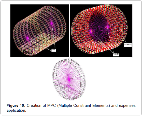
Figure 10: Creation of MPC (Multiple Constraint Elements) and expenses application.
Furthermore, for the purposes of the moment and the torsion, we define a moment of 5,000,000 in lbs, corresponding to a lateral gust for example, and a torsion 1,000,000 in. lbs. which corresponds for example to forces from the rudder when it is pressed.
We also need to apply boundary conditions to ‘fix’ the model. So we choose a node located at the junction between the floor and an extreme environment, where we block all translations (relative to the global benchmark). Then on vis-à-vis node that shares the same framework, we block the translations in Y and Z (relative to the global benchmark). Finally, we are left with only one degree of freedom: the model can still move in rotation on the Y axis (relative to the global benchmark).
To solve this, we then choose to block the translation of Y node in the middle of the floor on the two end frames (Figure 11). The model is thus ‘fixed’.
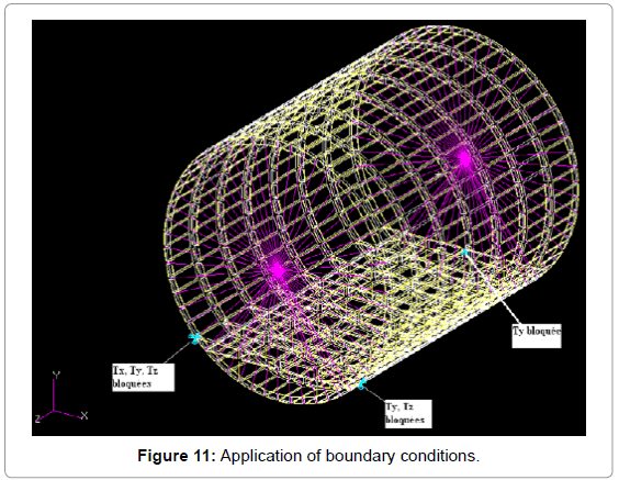
Figure 11: Application of boundary conditions.
We note that a finite element model ‘without porthole is also created in order to make comparisons, and better assess the effect of openings on the fuselage. This model is created from the modification of the one with windows, changing the properties of the surfaces of the windows that become identical to those of the coating. Then adding stiffeners which had been removed at the windows, taking care of their applied the same properties as the upper stiffeners.
General comments in such an analysis (static), the Nastran solver generates several files including a file whose extension F06. This is the file that will allow us to get detail results of the internal efforts. But before that, we can get an overall view of the effect of external load on the structure. For this, we need only read a Patran result files and then display the results in the form of color variation (color plot). By posting Von Mises stress, we get the equivalent stresses (Figures 12 and 13).
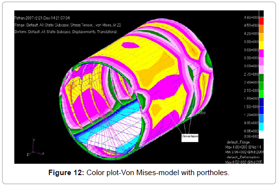
Figure 12: Color plot-Von Mises-model with portholes.
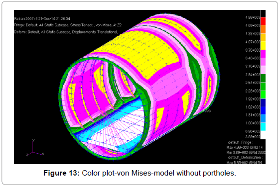
Figure 13: Color plot-von Mises-model without portholes.
We note that the application of SPC has effects on the surrounding structure, since the stress distribution is not symmetric with respect to the normal plan Z. Thus for better correlation of the results will be analyzed rather berries plants, that is to say those far boundary conditions.
In analyzing the results of the model with portholes, we can make some general remarks:
1) The distribution of equivalent stresses is not very uniform
2) The internal forces are small at the openings (about 3390 psi) as opposed to the rest of the coating (about 3690 psi)
3) The upper and lower surfaces of the bays where the openings are topics found to stress concentrations (approximately 3990 psi)
4) The adjacent frames are subject to stress concentrations (approximately 4590 psi)
5) The resulting σx=2300 psi average (which represent the longitudinal stresses) and σy=3260 psi average (which represents the circumferential stresses) are lower constraints previously calculated in the methodology section (Figures 13).
This can be explained by the presence of the floor, which includes part of these constraints (Figures 14 and 15).
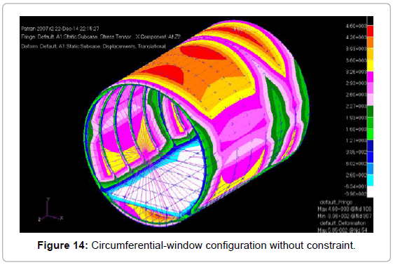
Figure 14: Circumferential-window configuration without constraint.
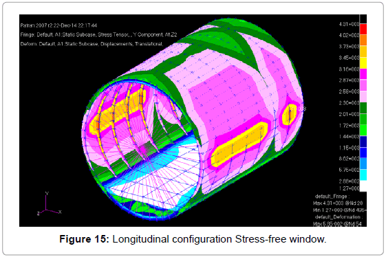
Figure 15: Longitudinal configuration Stress-free window.
Unfortunately this color distribution does not allow us to visualize the effects on the stiffeners. For this, we must look directly internal loads stiffeners result in the fo6 file.
The stiffeners
The internal loads in the ROD elements are represented in several ways. For our analysis we will use the ‘end loads’, which are made by a summation of “grid points balance force’, the balance of all the loads acting on a node in a given direction. This is basically free body diagram of a node; the sum of forces acting on a node must always be zero, giving a steady state to the node between the external loads and internal forces. And to realize the distribution of internal loads, we will seek end loads stiffeners bay 3 (adjacent to the central bay), and the bay 4 for configurations with and without openings (Figures 16 and 17).
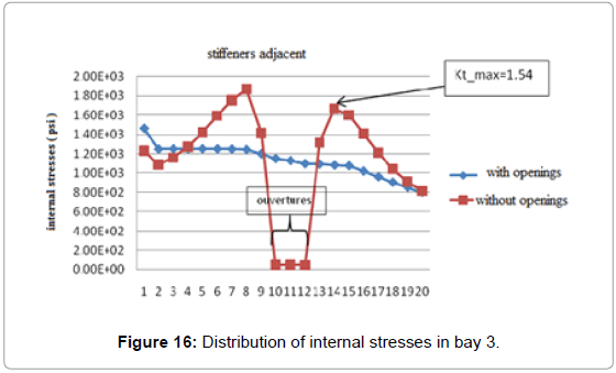
Figure 16: Distribution of internal stresses in bay 3.
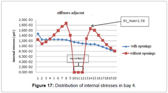
Figure 17: Distribution of internal stresses in bay 4.
The origin (0) represents the top of the fuselage, while the end (20) is the floor level. This reference system will be the same for all analyzes.
By analyzing these graphs and specifically the case with openings, we note that the stiffeners at the openings in the berry 3 do not include any load; their presence in this area is therefore virtually useless. By against the stiffeners located immediately above and below the openings experimenting stress concentration factors of up to 1.56. A strengthening structure at this level is then highly desirable. The frames are modeled by CQUAD elements and to know the internal efforts, we will seek, always in the f06 file, in the category ‘strengths in quadrilateral element’. This gives us the forces Fx, Fy and Fxy [12] (Figure 18).
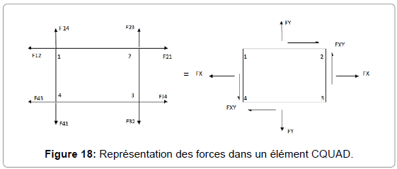
Figure 18: Représentation des forces dans un élément CQUAD.
 [12]
[12]
Once obtained these strengths, we calculate the maximum principal stress in order to have a comparison tool. This constraint is obtained as follows:
 [12]
[12]
In calculating the bending stresses it is usually assumed that the elementary beam theory is sufficiently accurate resulting in a bending distribution given by the equation  [12]
[12]
In order to agree with the bending theory the fuselage shear distribution over the frames should be in accordance to the shear equation  [12]
[12]
It is common practice to use the simplified beam theory in calculating the stresses in the skin and stringers of a fuselage structure. If the fuselage is pressurized, the stresses in the skin due to this internal pressure must be added to the stresses which resist the flight loads (ie σsk = σb + σL.) (Figure 9) illustrates a distributed stringer type of fuselage section.
Up to the point of buckling of the curved sheet between the skin stringers, all the material in the beam section can be considered fully effective and the bending stresses can be computed by the general flexure formula  [12] where Iy is the centroid moment of inertia of the section.
We analyze the frames 4 and 5 by comparing the configurations with and without openings (Figures 19 and 20).
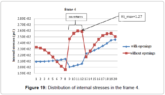
Figure 19: Distribution of internal stresses in the frame 4.
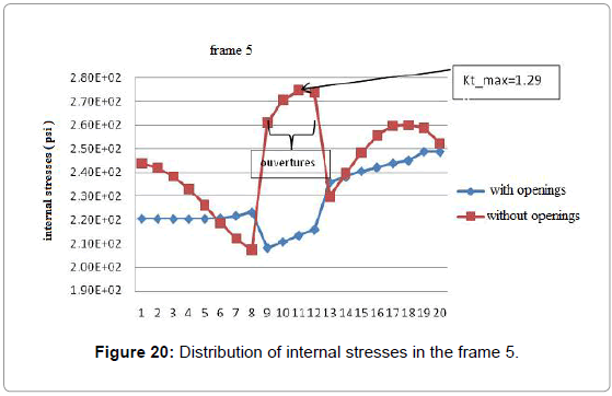
Figure 20: Distribution of internal stresses in the frame 5.
Compared to these two graphs and specifically the case with openings, we can say that the plates are at the openings, the top of the fuselage and about at the floor, undergo an increase in internal stress with a concentration factor stress up to 1.29. In addition, it appears that top plates and immediately resumes lower charges.
The skin
Compared to managers, the coating is composed of CQUAD elements. Thus the extraction method of internal forces will be the same. We analyze the plates of the bay 3 and 4 for the two configurations. Unlike following graphs, the latter two are a little different. This is explained by the fact that the bay 4 has possessed of openings unlike the bay 3. Thus, these openings due to their properties show fewer charges than the rest of the coating. Thus, we note the adjacent bay increased the internal stresses at the openings with a maximum stress concentration factor of 1.42. At the bay 4 additional charges are transferred immediately to the plates of the upper and the lower coating (stress concentration factor of up to 1.11) (Figures 21 and 22).
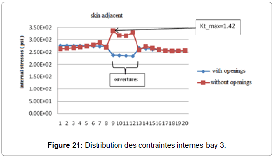
Figure 21: Distribution des contraintes internes-bay 3.
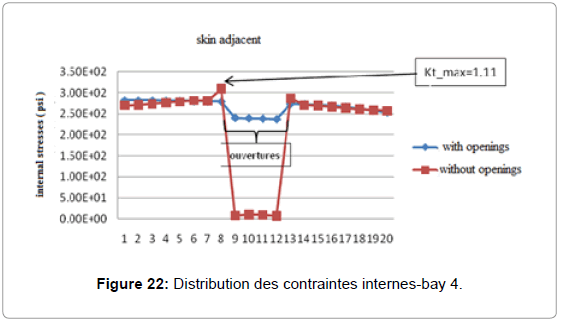
Figure 22: Distribution des contraintes internes-bay 4.
Effects of the moment with pressurization
(Figure 23 and 24) From these graphs, we clearly distinguish the effect of the openings increases of the internal stresses, up to about 1,14E4 psi instead of 8.29E3 psi below the openings (with a moment of 5000000 lbs.in). There has also reduced of the internal stress at the openings.
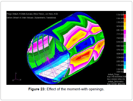
Figure 23: Effect of the moment-with openings.
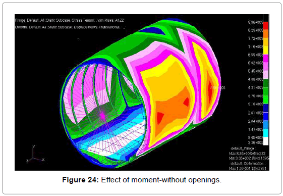
Figure 24: Effect of moment-without openings.
Effects of torsion with pressurization
(Figure 25 and 26) The openings effect when the body is subjected to pressure and torsion is less obvious to notice. Indeed the major changes taking place at the management level as shown by the figures. The openings level executives note that the plates show more charges if there are no openings.
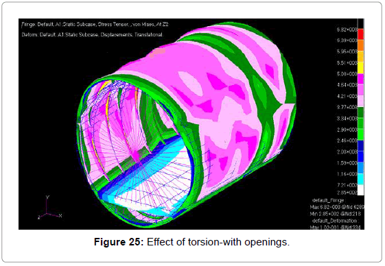
Figure 25: Effect of torsion-with openings.
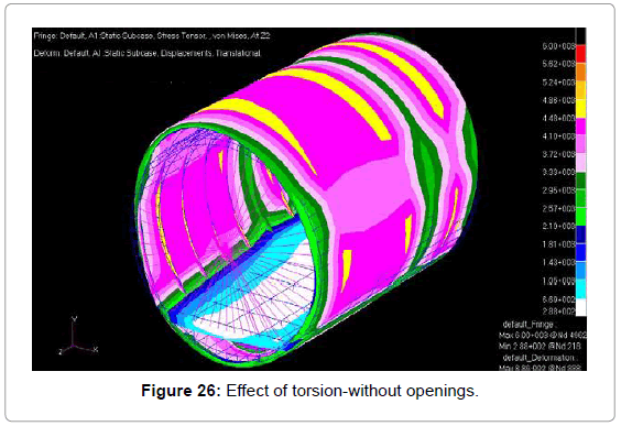
Figure 26: Effect of torsion-without openings.
Previous results are quite consistent, in that we realize the overall effect of the openings of the surrounding structure. Indeed, we can point to the views of different graphs, the new internal load distribution, and also the occurrence of stress concentration. The model constructed by finite element seems to be quite faithful to the only global representations of these effects. However, this model has some weaknesses, such an asymmetry with respect to the XY plane. Given that the fuselage has a symmetrical distribution of these elements (windows, frames, charges ...) we would have expected the same way to a symmetrical distribution of internal stresses. However we see from the above figures that it’s not really the case, contrasting the consistency of results. After investigation we realize that the application of travel restrictions (SPC) greatly influences the stress distribution. Made in the characterization made of the SPC is not really realistic. In flight, the fuselage is supported by the wings that generate lift, so it is normally at the junction between the fuselage and the wings that we would have the force displacement. But this is beyond the scope of our study, we decided to keep the boundary conditions as have already been established and defined above. Another weakness of the model is that when analyzing the results, we reported a flaw in the model with the configuration without openings. Indeed, as shown in (Figure 27), we notice at the openings, an abnormal decrease of the internal forces to the configuration without opening. A thorough investigation will probably solve this problem.
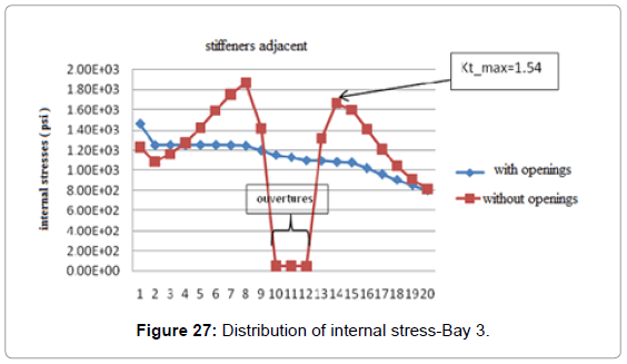
Figure 27: Distribution of internal stress-Bay 3.
The largest model of limitation lies in the fact that illustrates the overall effects and non-local. Indeed, the model is not refined enough to highlight precisely the value of internal efforts. We can only simulate the magnitude of the consequences of the openings in the fuselage structure.
Related to the aviation industry, the aim of the project was to realize the scale, and try to quantify stress concentrations at the openings, through a numerical method: finite elements. So from a geometric model, properties for elements and different load cases, 30 related to real situations in flight, we were able to visualize the phenomenon of stress concentrations. Thus we can realize the significant effect of openings in the structure of an aircraft. Indeed, these stress concentrations can be fatal if not pay attention. It is therefore essential to develop the structure accordingly to the most likely places to reduce the risk of damage. We tried to explain and comment on the phenomenon through this report, however, this study is only a first step to try to get closer to reality. In the future, it would be interesting to conduct a refining model to quantify precisely the stress concentrations. Or, to modify the boundary conditions to define those that best represent the reality for a given body structure. Finally, it could also be interested in the influence of the shape of the openings on the distribution of stress concentrations and thus devise solutions to reduce these concentrations and model them.