Journal of Aeronautics & Aerospace Engineering
Open Access
ISSN: 2168-9792
ISSN: 2168-9792
Research Article - (2023)Volume 12, Issue 1
A solid motor is a widely used propulsion system in the industry of aerospace. The application of solid propulsion has a wide range of advantages and disadvantages in space exploration and defence systems. The rocket performance is mainly described by the specific Impulse (Isp) produced by the propulsion system. The specific impulse has a very high significance in the design of a rocket and missile system. The paper is aimed to develop a numerical model for the prediction of specific impulse in a dual bell nozzle. The dual bell nozzle is a mostly used rocket that is used wide range in the industry of space exploration. The CFD simulation has been performed on the nozzle at different altitudes such as at the sea level, 4 Km, 8 Km, 12 Km, 16 Km, 20 Km, and vacuum. The simulation is performed with an inlet pressure of 7.34 MPa and inlet Temperature of 3410 K. and has a mass flow rate of the combusted gasses of 5.96 Kg/s. The simulation is performed that to observe the specific impulse of the solid motor rocket at different altitudes.
Computational fluid dynamics; Dual bell nozzle; Specific impulse; Pintle; Solid propulsion
P1: Pressure at the inlet; P2: Pressure at the outlet; ρ: Density; v1: Velocity at the inlet; v2: Velocity at the outlet; g: Acceleration due to gravity; y1: Height at the inlet from the ground; y2: Height at the outlet from the ground; HL: Head loss due to friction on walls in Bernoulli’s equation; Ω is the control volume with the surface 𝟃Ω; Vt: The contravariant velocity; nx, ny, and nz represent the cartesian components; Ln Length of the nozzle; K: Constant value; e: Area ratio of the nozzle; Rt: Radius of the throat; Re: Radius at the nozzle exist; qe: The angle of flow deviates ; F: Thrust; m: Mass flow rate; P3 Ambient pressure; Isp: Vacuum specific impulse
Propulsion is the act of changing the motion of a body. The propulsive force of a solid rocket motor is obtained by ejecting the propellant at high velocity. Accurate prediction of propulsion parameters is important for designing of solid rocket motor. CFD is a useful tool for the prediction of propulsion parameters. Many researchers have made use of CFD for their research work to study, design, analyze or predict solid propulsion elements and parameters.
CFD has a significant role in solid propulsion. Chongan Kim, et al. [1] explained the significance of CFD in the design and development of rocket propulsion. The nozzle is a component that is designed to increase the performance of air breathing and non-air breathing engines. Jiri blazek, et al. [2] described a solver useful to simulate the fluid in rocket motors. The reliability of code is of utmost importance for the analysis of flow in nozzles. Bogdon Alexandru Belega, et al. [3] used fluent 6.3 software for analysis of C-D nozzle with GAMBIT 2.4 software for numerical modeling and generation of mesh. Nathan Spotts, et al. [4] used Metacomp CFD++ software to conduct the study on compressible flow through convergent conical nozzles. A good comparison with experimental data is observed.
Laura, et al., [5] used Hopsan a multi domain software to study the performance of the sounding rocket. The results obtained are comparable with real performance. The simulations were further useful for the improvement of performance and increasing in altitude a rocket can reach. Supersonic exhaust diffusers were also analyzed using CFD. M Srinivasa Rao, et al. [6] performed numerical simulations for various rocket chamber pressures. The results have a good comparison with experimental data. K. Schomberg, et al. use CFD for the design of high area-ratio nozzle contours using circular arcs. The design offers an improvement in thrust coefficient and a reduction in average length. S. Saha, et al. analyzed combustion instability using CFD in solid rocket motors. The analysis was validated against motor test data available in the literature. Venkata Naga Mohan Manchiraju, et al. have performed a numerical investigation for predicting the specific impulse. It stated that the numerical data is almost similar to the experimental data. Jithendra Sai Raja Chada, et al. have studied the performance of nozzle with pintle with two different shapes.
The study stated that the nozzle with a prudent multi convex ramped shape has shown the best performance. Jiri Blazek has studied the flow simulation in solid rocket using advanced CFD, he had derived the equation for the rocket solid rocket motors. The study of the development of the test using modern Computation Fluid Dynamics (CFD) modeling of the engine workflow can be reduced the CFD-solver requirements a lot of the mathematic equation the set of combustion reaction and the design parameters are considered consist of 24 equations to solve the model the gas combustion equation and the chemical composition are observed in the paper and the design of the solid rocket motor and the rocket nozzle and the innovation in solid rocket motor and the design of the nozzle from the paper for this Study we had considered the different paper for the study for the obtaining the optimal result and the boundary condition of the simulation.
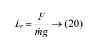
Specific Impulse is one of the important characteristics of rocket propulsion. It is a measure of fuel efficiency of the rocket, that is, the thrust imparted to the rocket per kilogram of the propellant expelled. If two different rocket motors have two different values of specific impulse, then the motor with a higher value of specific impulse is treated more efficiently. This is because the motor will produce more thrust for the same amount of propellant. It gives us an easy way to size a motor during preliminary analysis. The rocket weight will define the required value of thrust. Dividing the thrust required by the specific impulse will tell us how much weight flow of propellants our motor must produce. This information determines the physical size of the motor. Accurate prediction of specific Impulse (Isp) is important for the design of a solid rocket motor.
The designed nozzle is flow simulated in solidworks 2020. Solidworks uses navier stokes equations to solve the given model. In the engineering stream of study, fluid dynamics play e utmost role. And in fluid dynamics, Bernoulli’s theorem is a very salient concept. This theorem is uttered by a swiss mathematician Daniel Bernoulli. He expressed that if the flow of the fluid is horizontal i.e. not experiencing any alter in gravitational potential energy then reduction in the pressure of the fluid is correlated with the rise velocity of the fluid. He declared this theorem as during the effect, the entire mechanical energy of the streaming fluid containing the energy related to fluid pressure, the potential energy of elevation of gravitation, and fluid kinetic energy rest unchanged. Energy conservation is the concept to gives rise to Bernoulli's theorem. If the fluid is streaming between a horizontal tubes unlike a cross-sectional area, the fluid exercises a minimum pressure at the smallest area and vice versa.
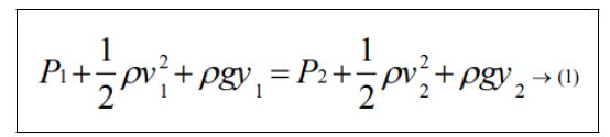
Where, P is the pressure, ρ is the density of the fluid, v is the velocity, g is the acceleration due to gravity, and y is the height. Subscripts 1 and 2 are for inlet and outlet respectively. Bernoulli's equations have the limitations as steady flow, incompressible flow, frictionless flow, and flow along streamline. But, the practical problems are analyzed by using extended Bernoulli's equation:
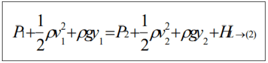
Where, HL is the head loss due to friction on walls. The navier stokes equation was named after the two scientists “Claudelouis Navier and George Gabriel Stokes”. These equations came to light by appealing to newton's second law of motion. Both in the scientific the engineering stream these navier stroke equations play a distinctive and functional role. In video games also these are used very massively. The connection between the pressures, temperature, density, the velocity of a streaming fluid can be studied. Navier-stokes equations re the addition and the extension of Euler’s equations which cover the upshot of the viscosity of the stream fluid. Continuity, three time-dependent, three time-independent equations together constitute the navierstroke equation.
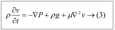
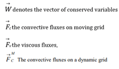
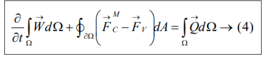
These equations are sometimes combined with additional equations called energy equations to solve typical applications. Equations being solved are the time-dependent Navier-Stokes equations in integral form on moving and/ or deforming grid.
The convective fluxes MFC → become on a dynamic grid.
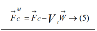
Vt being the contravariant velocity of the face of the control volume.
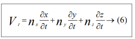
Where nx, ny, and nz represent the cartesian components of the outward facing unit normal vector of the surface. In order to avoid errors induced by a deformation of the control volumes, the Geometric Conservation Law (GCL) must be satisfied. The integral form of the GCL reads.
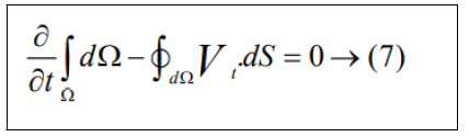
Additional equations have to be solved along with Equation (1) and (4) in the case of a multi-phase flow and for the species concentrations.
Design of dual bell nozzles
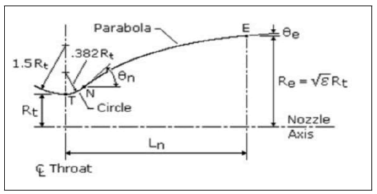
Jithendra Sai Raja Chada, et al. explained the design of a dual bell nozzle is constructed using a convergent part and the divergent forms from four curves: an initial, large circle coming from the inlet to the throat, a smaller circle exiting the throat, and a parabola to extend the approximated bell contour to the start of the second bell or counter to extend the approximated contour to exist plane is designed in the model (Table 1). The length of the nozzle is determined by the equation.
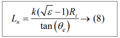
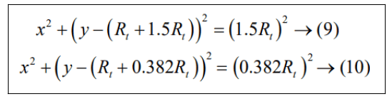
Where k is a constant value based up on the present of length of the nozzle. The flow deviates with an angle of θe. The radius of the throat is to be considered to be Rt. And e is considered as the area ratio of the nozzle. The center of the throat is described in two curves which the first curve and the second curve are defined as the entrance and exist of the throat respectively where the equation of the two curves is defined as the following:
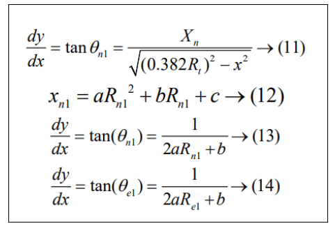
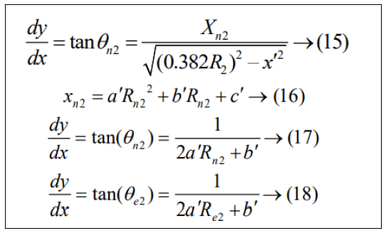
The equational coefficients are described with help of derivatives at the portion where the circle from the throat and the parabola coincidence, Xn, and the nozzle length. To describe Xn, the angle, Өn is mandatory to defined, the second curve equation must be equal to its tangent. Then the following equation is described as follows:
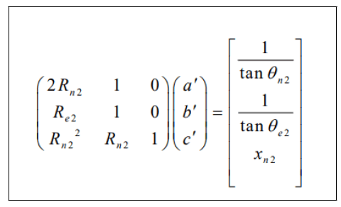
The equation can be described as matrix as the follow:
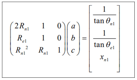
Which can then be solved for the coefficients.
The design of the nozzle is similar to the second counter also so we can:
And there matrix form is to be consider as follow:
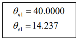
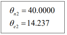
The convergent part is designed based on the area ratio and the angle is maintained at 45 degrees as constant and area ratio is defined consider as 11.2983 and the radius of the throat radius is 0.0305 m (Figures 1 and 2). As it is considered Dual-Bell Nozzle (First Contour) is the throat radius is 0.0305 m length of first contour is 0.3673 m. The angles of nozzle are:
The area ration with ε131.47 for second contour is as it considered Dual-Bell Nozzle (second contour) is the Throat Radius is 0.0305 m Length of first contour is 0.2732 m the angles of nozzle are:
The area ration with ε2=64.5603
The dimensions are indicated as follow:
| Type of Nozzle | Convergent part | first Contour | second Contour |
|---|---|---|---|
| a | - | 11.2983 | 21.8315 |
| b | - | 0.5084 | -4.7223 |
| c | - | -0.0208 | 0.5362 |
| Throat radius(m) | 0.0305 | 0.0305 | 0.0305 |
| Length(m) | 0.3673 | 0.2732 | |
| Theta_N | 45˚ | 40.00˚ | 20.0˚ |
| Theta_e | - | 14.23˚ | 9.58˚ |
| Area ratio | 11.2983 | 31.4754 | 64.5603 |
Table 1: Design dimensions of dual bell pintle nozze.

Figure 1: 2D geometry of dual bell nozzle.

Figure 2: 3D geometry of dual bell pintle nozzle.
Boundary conditions
The CFD setup contains boundary conditions and gas properties as inlet pressure is 7.34 MPa, inlet temperature: is 3410°K, outlet pressure: Are considered based upon the altitude, Nozzle wall: No-slip and adiabatic heat flux, and inlet mass flow rate are 5.96 kg/s.
Meshing and validation
The fine mesh is applied to the computational domain in which it is divided into 2,26,500 cells and simulation is carried out. The simulation took 7,680 iterations after which there is no change in the parameters under study.
Thrust force calculation
The thrust force obtained by the nozzle is calculated by the formula:
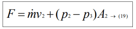
By using this formula, we had observed the thrust force produce by the solid rocket the thrust force is used to calculate the specific impulse of the solid rocket nozzle by using the formula:
The simulation is performed in manner at different altitudes the ambient pressure is considered below graph the altitude considered are 0 (Sea level), 4 Km (above the sea level), 8 Km, 12 Km, 16 Km, 20 Km, and vacuum pressure the bellow graph show that pressure (Psi and KPa), altitude in the ( feet and meter) (Figure 3).

Figure 3: The graph between the pressure and the altitude.
The simulation is performed in the boundary condition mention above the simulation performed the result are obtained are as bellow (Table 2).
| S.No. | Altitude | velocity | Pressure | Force (N) | specific impulse | Density | Mach no | Temperature | ||||
|---|---|---|---|---|---|---|---|---|---|---|---|---|
| outlet | max | min | outlet | N | (Isp) | min | max | Max | Min | |||
| 1 | Sea level | 2643.69 | 5639255 | 1661.297 | 930244 | 15008.81 | 256.7364 | 0.01283 | 5.7663 | 6.667651 | 3756.252 | 267.6512 |
| 2 | 4 Km above | 2616.029 | 5515115 | 992.5236 | 53570.37 | 14748.65 | 252.6683 | 0.007882 | 5.637845 | 6.608457 | 3794.279 | 232.2984 |
| 3 | 8 Km above | 2839.019 | 55562451 | 408.0269 | 24306.36 | 1575385 | 270.3836 | 0.004319 | 5.676321 | 11.10958 | 3769.765 | 140.5068 |
| 4 | 12 Km above | 2637.938 | 55782681 | 299.4557 | 3832.42 | 14187.72 | 243.8177 | 0.00348 | 5.69774 | 7.485914 | 3846.969 | 145.7563 |
| 5 | 16 Km above | 2539.255 | 55831220 | 210.6049 | 2390.81 | 14315.32 | 246.3183 | 0.002759 | 5.702667 | 7.6649 | 3750.53 | 235.6567 |
| 6 | 20 Km above | 2539.383 | 55831220 | 212.0018 | 2387.19 | 14780.8 | 254.6474 | 0.00277 | 5.702667 | 7.64365 | 3750.537 | 235.6894 |
| 7 | vacuu m | 2721.687 | 56666790 | 3308.974 | 1424270 | 28039.68 | infinity | 0.01962 | 5.78814 | 7.783673 | 3771.537 | 215.4443 |
Table 2: The obtained values of the simulation.
The Figure 4 represent the graph between the altitude and specific impulse the graph indicate that the specific impulse of the solid rocket apper in the way that the how the rocket motor that the specific impulse varyed the major specific impulse has been obtained at the altitude of 8 Km above the sea level.
The graphical representation is as follow:

Figure 4: The plot between altitude and specific impulse (Isp).
The Figure 5 represents the graph between the altitude and the thrust force. The maximum thrust force is also obtained at the 8 Km above the sea level.

Figure 5: the plot between altitude and force (N).
The Figure 6 represent the graph between the altitude and the outlet velocity of the rocket. The maximum outlet velocity is obtained at the altitude of 8 km above the sea level.

Figure 6: The plot between altitude and outlet velocity (m\s).
The Figure 7 represent the graph between the maximum pressure and the altitude the maximum pressure is the highest pressure which is obtained in the combustion process. The highest pressure is obtained in the vacuum.

Figure 7: The plot between altitude and max pressure (pa).
The Figure 8 represent the graph between the minimum pressure and the altitude the minimum pressure is the lowest pressure which is obtained in the combustion process. The lowest pressure is obtained in the 20 Km above the sea level. The simulation counter picture:

Figure 8: The plot between altitude and Min Pressure (pa).
The Figure 9 represent the how the flow occur in the simulation at the sea level and the velocity variation in the nozzle at the sea level similarly the Figures 9-12, represent for the 8 km above the sea level, 16 Km above the sea level, and at the vaccum.

Figure 9: The velocity counter at the sea level.

Figure 10: The velocity counter at 8 Km above the sea level.

Figure 11: The velocity counter at 16 Km above the sea level.

Figure 12: The velocity counter at the vaccum.
CFD is a useful methodology for predicting the rocket motor/ nozzle performance. The CFD results can be used to accurately predict other parameters like temperature, pressure, velocity, and density at any point in the nozzle. This data will help designers in the selection of appropriate materials for nozzle fabrication. Flow features like expansion waves and oblique shocks occurring inside the nozzle can be captured accurately. This will help the designer to design the divergent contour free of any flow irregularities and flow separation. After simulation we got how the specific impulse of the solid motor is varying at different altitude. We know as the specific impulse increases the trust and efficiency of the rocket increases. The design can be further modified to increase the specific impulse. Also, chamber pressure and burn rate are also very important parameters and they depend on the propellant chosen for the system and chamber dimensions. So, a good selection of these parameters is a determining.
Mr. Jithendra Sai Raja Chada is an under graduate scholar pursuing his Bachelor’s Degree (BTech) in mechanical engineering at Pragati Engineering College. His current research interests include CFD, industrial design, nano materials, manufacturing. He have published 17 research articles in various international journals and published 3 monograph. Mr. Sri Ram Deepak Akella. Is an undergraduate research scholar who is perusing his bachelors in the field of mechanical engineering at Pragati Engineering college his area of research is His current research interests include CFD, aircraft and rocket design, thermal engineering, heat transfers, combustion and propulsion systems, nanomaterials, and robotics. He had published 12 research articles and had published 1 monograph.
Jithendra SR Chada: Design, methodology, simulation, visualization, conceptualization. Sri R D Akella: Formulation, paper writing, resource and data collection.
Citation: Chada JSR, Akella SRD (2023) Prediction of Solid Rocket Motor Performance in a Pintle-Dual Bell Nozzle Using Computational Fluid Dynamics. J Aeronaut Aerospace Eng. 12:298.
Received: 09-Oct-2022, Manuscript No. JAAE-22-19509; Editor assigned: 11-Oct-2022, Pre QC No. JAAE-22-19509 (PQ); Reviewed: 25-Oct-2022, QC No. JAAE-22-19509; Revised: 10-Jan-2023, Manuscript No. JAAE-22-19509 (R); Published: 17-Jan-2023 , DOI: 10.35248/2168-9792.23.12.298
Copyright: © 2023 Chada JSR, et al. This is an open-access article distributed under the terms of the Creative Commons Attribution License, which permits unrestricted use, distribution, and reproduction in any medium, provided the original author and source are credited.