Advances in Automobile Engineering
Open Access
ISSN: 2167-7670
ISSN: 2167-7670
Research Article - (2016) Volume 5, Issue 2
Diesel fuel is injected into the combustion chamber by the use of injectors. Atomization process is characterized by directing extremely pressurized fuel into the injector orifices in modern injectors. However, this high pressure level, which exceed 1300 bars in some cases, causes cavitation before discharge nozzle and results in mechanical wear. In air assisted atomizers, pressured air is utilized for atomization. This type of injectors eliminates cavitation erosion by reducing injection pressure and they create finer spray geometry. Mixing process of air and fuel has a vital importance since it directly affects level of atomization in air assisted atomizers. Therefore the aim of this study was determine influence of different inlet port geometries on flow characteristics of a specially designed diesel injector which is developed for diesel fuel atomization, by using computational fluid dynamics techniques.
<Keywords: Diesel engines; Injector; Spray; CFD
Now-a-days, there are number of expectations from diesel engines; such as running over a wide operating range with high efficiency and generating low exhaust gas emissions. This will require high combustion technologies such as turbocharging and high pressure injection. Fuel injection process is the most important phenomena that control combustion and emission formation. In order to ensure efficient combustion; fuel should be perfectly atomized during injection process. With today’s injectors atomization is commonly realized with highly pressurized common rail diesel injectors. However, cavitation occurs in the injector nozzle due to high pressure gradients within the injector. It is very difficult to observe the turbulence created within the diesel injector nozzle and its effects on cavitation formation with experimental techniques due to extremely small size of the holes, the existence of a multiphase flow and the high velocities created near the discharge orifices [1]. Several efforts have been expanded in order to explore effects of cavitation phenomena on spray characteristics of diesel injectors by several researchers [2-4]. Despite its advantages such as keeping the nozzle free from deposits, generating the spray [5]; cavitation unfortunately may lead to mechanical failures. Therefore, it is very important to reduce injection pressure by the use of second atomizing gas.
There are number of advantages of utilization of air in diesel engine injectors, such as lowering engine emissions, providing fuel economy and enhancing volumetric efficiency with extra air addition into combustion chamber. In addition, assisted atomizers are able to provide the finest degree of atomization for a given flow capacity and supplied pressures. The spray pattern remains stable as far as the velocity of the atomizing air is maintained. Air assisted atomizers are widely used in the combustion applications. Compared to pressure atomizers which require high pressures for atomization; air assisted atomizers can provide a fine spray at relative lower supply pressures [6]. There are many studies focus on air assisted atomizers [7,8].
Therefore, this work focuses on simulation of the internal flow of an air assisted diesel injection device which improves combustion by mixing air and fuel inside itself at optimum ratio. Air is directed to diesel fuel within the injector in order to increase atomization level of diesel without extremely pressurizing the fuel. Effects of varying fuel inlet port geometries on flow characteristics within the designed diesel injector were examined, by this way mixing process of air and diesel within the injector was explored.
The structures of different air assisted injectors designed in the present study are shown in Figure 1. The design parameter of this study about the injector was the fuel inlet port geometry. The structure of fuel inlet port of the injector is very important since it provides fuel into the mixing chamber and mixing chamber arranges fuel air mixing process which has a vital importance for spray formation. Three different numerical models have been developed in order to study the influence of different fuel inlet port geometries on flow characteristics of the injector. In the first design the angle between fuel inlet and air inlet (α) was set to 90 degrees (Case 1). In the second design α was set to 60 degrees in order to identify effect of different contact angles on mixing characteristics of diesel and air (Case 2). Finally, two symmetric fuel inlet ports were used in the third design.

Figure 1: Demonstration of the injector assemblies used in simulations.
The CFD analysis has been carried out in CFX software, which is available in ANSYS Workbench 14. In order to simulate mixing of diesel fuel and air phases to the program, diesel fuel and air properties from the program library were used. Diesel phase is introduced to the mixing chamber via fuel inlet. The following equation was used in order to calculate the amount of fuel injected per cycle:
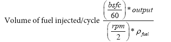 (1)
(1)
If BSFC (Brake Specific Fuel Consumption) of the engine is considered as 0.3 kg/kWh and specific gravity of the diesel fuel is considered as 0.87; the volume of diesel fuel injected per cycle at 1500 rpm will be:
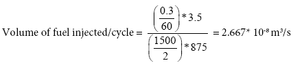
Therefore, initial volumetric flow rate of diesel fuel is taken as 2.667 × 10⁻⁸ m3/s for all simulations [9].
The air is supplied at 60 bars through air inlet port. By the effect of vacuum created by relatively high pressure air, fuel is sucked in to the mixing chamber where air and diesel phases are mixed together. This two-phase flow comes out from the injection orifice of the injector.
CFD simulations obtained from three different inlet port geometries were discussed in this section. CFD studies helps at further understanding of air and fuel flow structure. The mixing process of fuel and air phases was explored and optimum fuel inlet port was selected. The analyses are realized on the basis of turbulence intensity and velocity profiles of diesel and air phases.
Turbulence intensity analysis
The mixing efficiency is very important for quality of combustion. Diesel and air phases should be mixed perfectly at molecular level in order to provide better atomization which results in high quality combustion. Turbulence level created within the mixing chamber is very important since it enhances mixing. Turbulence is created mostly due to fluctuations in the flow field. Figure 2 shows turbulence intensity contours of different fuel inlet designs with 90o (Case 1) and 60o (Case 2) contact angle and double fuel inlet (Case 3). Figure 2 displays that 60o inclined fuel inlet enhance turbulence level within the injector whereas 90o contact angle results in non-uniform turbulence which causes non-uniform mixing of diesel and air phases. In Case 3, turbulence level within the injector is found to be higher compared to Case 1 and Case 2. This enhanced turbulence level owing to the geometry of inlet provides better suction of the diesel fuel into the mixing chamber.

Figure 2: Contours of air turbulence kinetic energy within the injector.
Velocity analysis
Diesel velocity contours generated within the injector for different fuel inlet port geometries are shown in Figure 3. Diesel velocity distribution along the injector should not decrease below a certain level in order to obtain desirable level of atomization. Figure 3 shows that low velocity zones are created within the injector for Case 1, and Case 2; whereas there are no such zones for Case 3. The study of velocity contours within the injector revealed that only a weak velocity stream is created within the mixing chamber for Case 1 and this velocity stream slowly disappears close to nozzle entrance channel. Similar trend is also obtained for Case 2, velocity of diesel decreased within the injector compared to mixing chamber. However, as shown in Figure 3, for Case 3, the velocity of diesel is kept constant until the nozzle as demonstrated by velocity profile? Therefore, the results showed that there will be an enhanced mixing of the diesel with air for Case 3.

Figure 3: Contours of diesel velocity within the injector.
Velocity distribution within the injector is quantitatively shown in Figure 4. Figure 4 expresses that; velocity of diesel shows similar trends for all of the designs. Diesel velocity decreases inside the mixing chamber and it is kept constant until the nozzle. Maximum velocity is obtained at the exit orifice of the injector. Maximum injection velocity is obtained for Case 3 at about 1200 m/s whereas minimum velocity value is occurred for Case 1.

Figure 4: Variation of diesel velocity throughout the injector.
Three different air assisted diesel injectors are developed in this study and their atomization performance are estimated by conducting flow analysis within injector by the use of CFX software of ANSYS Workbench 14. It is seen that the double fuel inlet provides a higher turbulence at the mixing chamber and ensures a better suction of fuel which ultimately enhances the mixing of air and fuel phases. The velocity contours analysis indicated that; there are low velocity zones for the single fuel inlet having injectors whereas there are no such zones are occurred for double fuel inlet having injector. Finally; air assisted fuel injector with double inlet is advised in order to provide proper air fuel mixing and create proper atomization.