Journal of Aeronautics & Aerospace Engineering
Open Access
ISSN: 2168-9792
ISSN: 2168-9792
Research Article - (2018) Volume 7, Issue 2
The present project sets out the analysis of mechanical behaviour of a carbon-epoxy stiffened panel under bending load. For this purpose, the National Polytechnic Institute of Mexico counts with a non-airworthy B727-200 as experimental platform. The first step was to calculate the aerodynamics loads and flight envelope of the aircraft. Secondly, the selection of the fuselage section is performed in order to identify an adequate stiffened panel for the study. The structural elements of the panel, skin and stiffeners were manufactured by VARTM and glued with high strength adhesive. The load, in bending condition, was imposed by a structural testing machine in order to emulate, at lab scale, the flight conditions responsible for debonding the stiffeners from the skin. The displacement field was determined by Digital Image Correlation (DIC) and the strains values at key zone of the fuselage by gages measurements. Finally, the failure mechanisms were analyzed with the goal to improve the knowledge of the stiffened-skin glued joint solution.
Keywords: Aircraft structures, Bonded joints, Carbon/epoxy, Debond crack, DIC
Now-a-days, aircraft companies find technological challenges in order to satisfy simultaneously technical, economical and logistical requirements of commercial airplanes with more than 50% mass in composite materials. The aeronautics design methodology, known as the pyramid of tests [1], deals with new structural concepts which post several questions that are not still fairly answered on the design, manufacturing and repairing processes.
The pyramid of tests deals with five levels of mechanical tests, according with the size and complexity of samples [1,2]. In the first step, simple coupons are tested with the aim to obtain baseline properties for materials. The second level is committed to basic elements such as shells, beams and stiffeners. After that, the third level is defined by the union of two or more basic elements to create structural details such as stiffened panels or wing-boxes. The fourth level is then dedicated to gather several details to assembly a structural component like a wing, elevator, or fuselage sections. At the end, the fifth level considers testing of the whole aircraft in order to obtain airworthiness certification, which includes testing under real service conditions with destructive techniques [3].
Dealing with any aeronautical structural detail involves four aspects: 1) composite structure with singularity details; 2) multi-axial modular testing machine; 3) multi-scale numerical modeling and 4) multisensor instrumentation [4]. Concerning the composite structure, this one has to be created case by case, in a representative scale, in order to regroup the specific singularity details of interest, such as stiffener–skin interfaces. For the multi-axial modular testing machine, this must have the means to apply mechanical, thermal and/or electrical loads very similar to those found on the real composite structures [5,6]. One of the many advantages to build an in-house testing machine is the capability to design it with the specific needs of the research. The aspect of multi-scale numerical modeling, concerns Finite Element models (FE-models) of the composite structure and the application of boundary conditions estimated from aerodynamics and structural calculations [7,8]. Finally, the multi-sensor instrumentation, takes advantage on placing sensors inside and outside the composite structure. The instrumentation can be done by using multiple devices (optical fibers, piezoelectric, tunneling sensors, thermocouples, and strain gauges) combined with non-contact technique such as Digital Image Correlation (DIC) [4,9,10]. By confronting the numerical and experimental data sets an accurate calculation/test correlation can be achieved. All these interactive tasks provide a better back-feed to improve the structural design of the next generation of aircrafts.
Now-a-days, stiffened panels offer competent performance for aeronautics applications. The study of stiffened panels on composite materials takes place at the third and fourth level of the pyramid of tests, due to the bolted/fastened/glued joints to bond the skin and the stiffeners. During the last decade, glued joints solutions have been on discussion, in order to establish the best design, analysis and repair practices [11,12]. During service, the stiffened panels are submitted to combined stresses state which cause a complex interaction of failure modes leading to the ultimate failure of the structure. Moreover, current studies relate the deboned size with crack initiation, not necessarily propagating, and the damage tolerance of the panel [13]. Additionally, due to the geometric imperfections of the singularity details, the stiffened panels are more bound to present local and global buckling [14,15].
Because the new trends on aeronautics design and repairs, research is conducted on the residual capabilities of stiffened structures containing prior delamination’s and associated damage. In order to evaluate the mechanical performance of stiffened panels and its intrinsic failure modes, technological approaches according to the pyramid of test need to be proposed.
In this sense, Mexican institutions have gathered scientific efforts to develop their own aerospace hard patch initiatives to repair primary structures. This strategy consists in designing a set of composite panels based on B727-200 non-airworthy aircraft to test optimized bonded repairs. The design of the repairs for the stiffened panels will be done using the innovative philosophy of the Multi-Instrumented Technological Evaluator Toolbox [4,16]. Based on limited-sized specimens called Technological Evaluators, the MITE Toolbox is conceived for monitoring structural components from the very beginning of the manufacturing process till the in-service condition, with the aim to study bonded, riveted and bonded/riveted interfaces, to optimize stress transfers during mechanical tests, or to design new repairing configurations.
Thanks to the MITE Tool-box, this project wants to take advantage of this aircraft as experimental platform which premises representative loads that can be applied for an extremely low cost compared to the investment for typical scale one tests. Therefore, it is a major opportunity to validate the mechanical performance of bonded composite panels as primary structures and to demonstrate, if possible, that these new structures could be certified.
Aerodynamic and structural calculations for the fuselage stiffened panel
The IPN of Mexico has a non-airworthy B727-200 aircraft, which can be used as scale-one experimental platform (Figure 1a). This aircraft offers the opportunity to study representative scenarios for designing, repairing and replacing large zones on the nose radome, fuselage, wing and elevators. As initial study case, the approach was to select a fuselage panel candidate, first to be reproduced at lab scale, and then, to be evaluated in-situ on the aircraft. The selected panel belongs to section 43, between the 720 and 720-A frames (Figure 1b) [17].
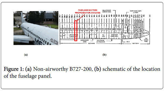
Figure 1: (a) Non-airworthy B727-200, (b) schematic of the location of the fuselage panel.
Previous work has been done to calculate the aerodynamic and structural forces acting on the selected fuselage panel. The loads relevant to the fuselage are caused by three sources: 1) aircraft maneuvers, 2) aircraft weight distribution and 3) cabin pressurization. Following the weight fractions method [18], the weight for all components of the aircraft was estimated using the maximum take-off weight. The basic engineering criterion to design a fuselage is to consider it as a balanced beam under distributed load with only one middle support. For the aerodynamic forces, the maneuver and gust envelopes were calculated to identify the critical design scenario for the fuselage panel, resulting on cruiser speed and maximum load factor (Figure 2a). Additionally, the cabin differential pressure at cruiser altitude is taken into account for the stress calculation. The effect of all these loads can be summarized in a load distribution diagram through the length of the fuselage (Figure 2b).
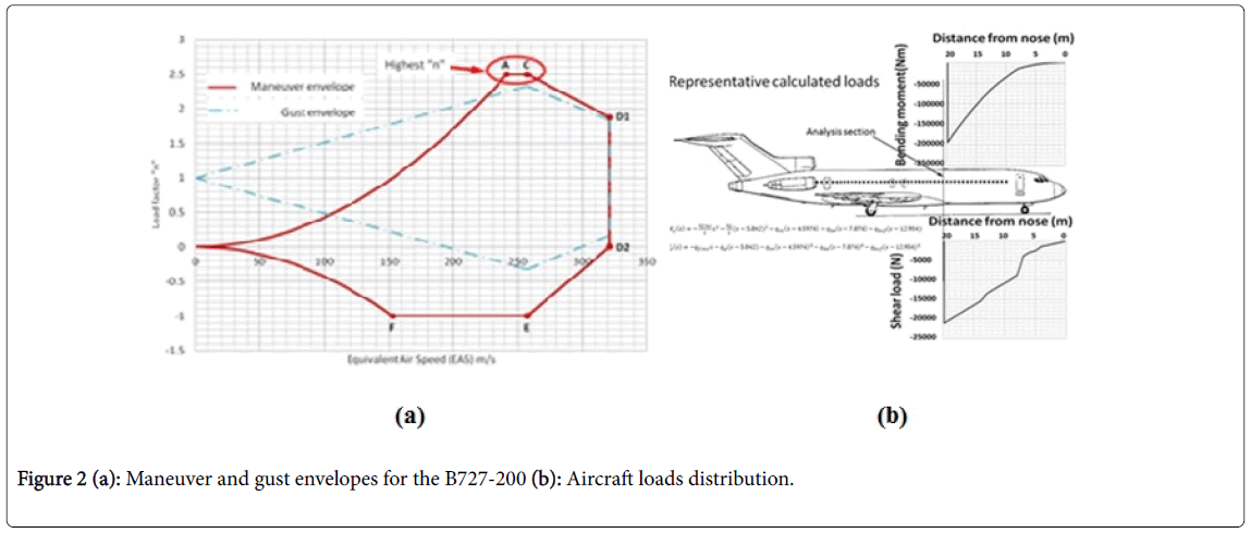
Figure 2: (a): Maneuver and gust envelopes for the B727-200 (b): Aircraft loads distribution.
Once the loads for the fuselage’s section were determined, the stresses for the panel were calculated. Because the fuselage section is located at the body crown just before the rear front spar attach frame, the panel stress state is caused by the cabin pressurization plus the bending moments. For this particular section, the panels are submitted to three different stress states: 1) maximum axial stress and minimum shear stress, 2) average shear and axial stresses and 3) maximum shear stress and average axial stress. As example, three different panels, one for each stress state, were calculated (Table 1).
| Panel | Axial stress (σx, MPa) | Hoop stress (σc, MPa) | Shear stress (τxy, MPa) |
|---|---|---|---|
| 01-Feb | 180 | 160 | 10 |
| 08-Sep | 140 | 160 | 50 |
| 15-16 | 60 | 160 | 60 |
Table 1: Stress state for different panels from B727-200 section 43, between 720 and 720A frames.
The three cases are representative conditions for fuselage panels during cruiser. However, because of the labs infrastructure, accessibility and scope of the global project, it was decided to keep a fuselage panel submitted to maximum axial stress and minimum shear stress; therefore, the selected panel is located between stiffeners 1 and 2, placed on the top of the 43 cross-section (Figures 3a and 3b) [19]. Also, this load configuration is the most adapted to induce debonding between the stiffeners and the skin of the fuselage.
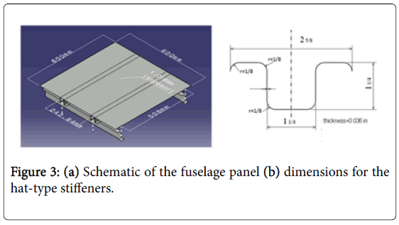
Figure 3: (a) Schematic of the fuselage panel (b) dimensions for the hat-type stiffeners.
Design and manufacturing of the fuselage stiffened composite panel
In the last five years, the exponential increment of composite based aircrafts have led to the airlines and MRO companies to treat with composite elements, which have much more complex failure mechanisms on metallic parts.
Due to airworthiness constraints, the composite structural components are riveted. Numerous efforts are being done in order to reduce the induced damage caused when composites are drilled and riveted.
Nonetheless, in order to take profit from optimized designs of composite parts and to reduce the number of rivets, the glued/bonded joints have gained major interest [13-17]. The main difficulty is to demonstrate, to the airworthiness agencies, the validity of the bonding solution for designing or repairing an aircraft component.
For these reasons, it was decided to fabricate the selected fuselage panel with composite materials. As first approach, the fuselage panel was manufactured with 3K-70-P carbon plain weave plies and EPOLAM 2015 epoxy system provided by Axson®. Both skin and tophat stiffeners have a [0/90]4 layup and were manufactured by Vacuum Assisted Resin Transfer Moulding (VARTM), where curing last 16hrs at RT (Figures 4a and 4b). After demolding and cutting to have appropriate dimensions, stiffeners were glued with MP 55300 methacrylate-based structural adhesive from ASI® (Figure 4c).
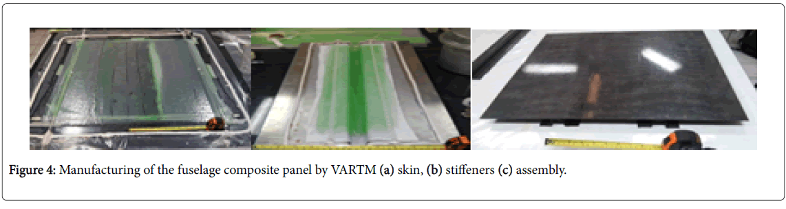
Figure 4: Manufacturing of the fuselage composite panel by VARTM (a) skin, (b) stiffeners (c) assembly.
Mechanical testing of the fuselage stiffened composite panel
As first approach, the stiffened composite panel was tested in an inhouse built representative structural testing banc (BESTER) designed for the test of UAV’s structures (Figure 5a).

Figure 5: Mechanical test of the composite panel (a) in-house testing banc, (b) and (c) DIC setup.
The Bester has two modular servo-hydraulic actuators providing a maximum loading capacity of 20 kN (2 Ton). At full range, the BESTER is capable to reproduce 1/10th (20 kN-m) of the calculated bending moment for the fuselage’s 720-720A cross-section (200 kNm).
In order to represent at lab-scale the stress condition calculated (cf. section 2), the composite panel is constrained in cantilever condition, fixing one side of the panel and applying the bending load on the other side with one servo-hydraulic actuator through a metallic brace (Figure 5b).
This loading condition is the best fit to emulate, at lab-scale, the bending moment acting on the fuselage panel. As we want to induce debonding on the stiffener-skin interface, this configuration is the more suitable to pursuit this objective, according to size and technical limitations of the structural testing banc.
The instrumentation of the composite panel consists in three strain gauges; two located on the stiffener-skin zone near the fixed side and one located at the center of the fuselage panel. Additionally, the skin was painted with a white speckle pattern with the aim to employ Digital Image Correlation (DIC) during the test (Figure 5c). A set of two CCD cameras is placed and calibrated for making image acquisition without visual alterations.
The CCD cameras had lens with 2.4 mm of diameter and 70 mm of focal distance. The region of interest selected (ROI) is the total surface of the skin of the panel. Once the images are captured, the software GOM-Aramis is used for the images post-treatment.
The fuselage stiffened composite panel subject to bending condition presents a linear behavior prior to failure, caused by debonding of the stiffener-skin interface. The load-strain curves, obtained by strain gauges measurements, show that the stiffener-skin zones near the fixation (Gauges 1 and 3) are the most constrained when the composite panel is under bending moment.
The skin zone (gauge 2) is less deformed; as the mid-zone of the panel carries a lower load compared to the stiffeners reinforced zones (Figure 6). As it can be seen, strain values from digital image correlation are over-estimated compared with the strain values obtained from strain gauges. As stiffener-skin zones are symmetrical, only one DIC strain-load curve is showed.

Figure 6: Load-strain curves for the fuselage panel by strain gauges measurements.
For all displacement fields obtained by DIC, the most elongated areas are the zones between the stiffeners and the two free-edges of the composite panel, near the fixation. On first place, the displacement field perpendicular to the stiffeners (Figure 7a) shows a small displacement variation between the two free-edges zones, which can be related to in-plane shear strains caused by a misalignment between the fixation’s center and the metallic tensile brace.
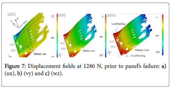
Figure 7: Displacement fields at 1280 N, prior to panel’s failure: a) (ux), b) (vy) and c) (wz).
On second place, the displacement field parallel to the stiffeners (Figure 7b) reveals a negative displacement on the loading side, inherent to the compression stresses that the composite panel suffered during the bending test. This displacement field also reveals that the zones between the stiffeners and the panel’s free-edges are the most constrained. Because the panel is under compressive stress state, the skin between the stiffeners and the free-edges presents local buckling. On third place, the panel’s out-of-plane displacement field (Figure 7c) proves that the fixed side exhibits a lower displacement than the loaded side, as expected.
As the skin is mostly submitted to compressive stresses, the analysis of the strain field (εyy) parallel to the stiffeners (Y-axis) is the more relevant for this study. The evolution of the strain field (Figure 8) clearly shows that the fixed side of the panel is the most strained, where strain concentrations appear between the stiffeners and the panel’s free-edges.
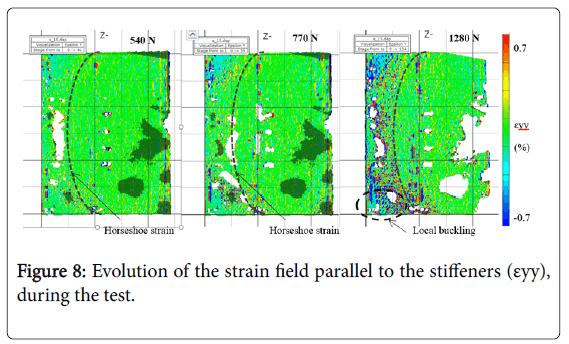
Figure 8: Evolution of the strain field parallel to the stiffeners (εyy), during the test.
The strain field shows a horseshoe type morphology which is related to the skin’s local buckling due to the combined shear and bending condition to which the upper surface of the fuselage panel is submitted. The skin being under compressive stress causes the panel’s geometric instability, leading to stiffeners-skin interface’s debonding which results in a complete loss of the panel’s load-carrying capacity.
The current work summarizes the calculation, design, manufacturing and testing of a scale-one B727-200 fuselage stiffened composite panel to evaluate the performance of stiffener-skin bonded joints. As the composite stiffened panel is subject to bending load, the out-of-plane shear stresses on the stiffener-skin interface, combined with the skin’s local buckling are the main source of the stiffener-skin debonding. Strain gauges measurements and DIC displacement and strain fields prove that the boundary between the skin and the stiffener are the most constrained zone of the panel. Further work includes a quantitative comparison between the strain values obtained by DIC and strain gauges, in order to fulfill the calculation-test correlation. Additionally, a buckling analysis of the fuselage composite panel is being done in order to estimate the load-carrying capacity of the panel before and after instability. This first study case gives us more experience in defining the mechanical performance of glued joints for fuselage structural elements. The ultimate goal of the project is to perform a one-scale test, substituting a metallic panel with a composite panel, on the B727-200 platform.
The authors convey their special appreciation to the National Council of Science and Technology of Mexico (CONACYT), the National Polytechnic Institute of Mexico (IPN) for their financial support. Grant numbers related: CONACYT 251208 and 271817, IPNSIP 20151776.