Journal of Theoretical & Computational Science
Open Access
ISSN: 2376-130X
ISSN: 2376-130X
Research Article - (2015) Volume 2, Issue 4
The most effective simulations of complete physical problems consist of the evaluation of maximum water levels and discharges that may be attained at particular locations during the development of an exceptional meteorological event. There is also the prevision of the scenario subsequent to the almost instantaneous release of a great volume of liquid. The situation is that of the breaking of a man made dam. There is therefore a necessity to develop a model capable of reproducing solutions of the complete equations despite the irregularities of a non-prismatic bed. This requires the development of efficient and effective numerical schemes able to predict water levels and discharges in hydraulic systems. The use of mathematical models as a predictive tool in the simulation of free surface flows represents a good candidate for the application of many of the techniques developed in fluid dynamics. In this paper we develop a 1-D complete model of shallow water equations with source terms using both conservation of water mass and conservation of the momentum content of the water. We describe the Lax-Wendroff scheme for these nonlinear partial differential equations (PDEs) and we analyze the stability restriction of the method. This extends the nonstationary shallow water problems without source terms which are deeply studied in literature. Some numerical experiments are considered and critically discussed.
<Keywords: 1-D shallow water; Saint-Venant equations; Source terms; Lax-Wendroff scheme; Von Neumann or Fourier stability analysis; Stability restriction
Most open-channel flows of interest in the physical, hydrological, biological, engineering and social sciences are unsteady and can be considered to be one-dimensional (1-D). In unsteady flow, some aspects of the flow (velocity, depth, pressure, or another characteristic) is changing with time. In 1-D flow, longitudinal acceleration is significant, whereas transverse and vertical accelerations are negligible. Many interesting problems involving 1-D nonstationary flows have been approximated by assumption of steady flows (for example, constant peak discharges in flood plain delineation studies) or piecewise steady flows, where in storage outflow relations are derived for channel reaches from a steady flow hydraulic model and used in simple hydrologic routing methods. Piecewise steady flow analysis typically does not consider all the forces acting on the flow and only partially accounts for channel storage effects. The approximate solutions for steady flow and piecewise steady flow analysis are adequate for certain simplified planning or design problems but are inadequate for many others (for example, streams with rapidly rising and falling stage, flat slopes, and broad flood plains where storage and acceleration effects could be substantial). No criteria are available to guide researchers especially, when steady flow methods are acceptable and when a complete unsteady flow analysis is necessary. Further, problems such as tidally affected flows and sudden releases from power generation stations require 1-D unsteady flow analysis. In general only nonuniform unsteady flow is of interest in hydraulic analysis.
Three conservation principles: conservation of water mass, conservation of the mechanical energy content of the water and conservation of the momentum content of the water are available for analysis of 1-D unsteady flow. Conservation of thermal energy is not considered because temperature change and heat transfer effects do not affect flow depth and discharge. In some works [1-5] researchers provide a detailed list of differences between the energy and momentum approaches and argue for combined application of the conservation of mass and conservation of momentum principles as the equations of motion because this combination gives the correct wave speed and height should abrupt waves (hydraulic bores) form during the modeling of rapidly increasing or decreasing flow. In contrast, application of the conservation of energy principle provides no simple approximation that can be applied to yield the correct wave speed and height. The applicability of the conservation of momentum principle to the solution of lateral inflow problems has been demonstrated in modeling of side channel spillways and wash water troughs (for example, [6]), both of which cause much greater turbulence than normally results in unsteady flow. In order to take care of this problem we can follow different approaches: for instance in [7] the authors give further evidence for the choice of the momentum conservation principle. Further, because the use of Manning’s equation for resistance losses yields a better estimate of the resistance coefficient for the momentum principle than for the energy principle, methods based on momentum conservation yield better estimates of the water surface profile than do methods based on energy conservation, especially if Manning’s number n1 is calibrated to measured water-surface profiles or historic high water marks. In addition, the resistance coefficient estimated from the momentum principle was insensitive to variations in the velocity of lateral inflow (many applications of unsteady flow involve a wide range of lateral inflow rates). Finally, the equation obtained with the conservation of momentum principle is simpler than the equation obtained with the conservation of energy principle.
In the analysis of unsteady flow in open channels, using suitable assumptions [8], formal statements of the conservation of water volume (mass) and conservation of water momentum can be developed. No forces of any kind are considered in the conservation of mass. Forces, momentum fluxes and the momentum of water in storage are related in the conservation of momentum principle. If all the factors are included in the analysis, the equations are referred to as the complete Saint- Venant or shallow water equations with source terms
The 1-D complete Saint-Venant equations with source terms solved by analytical method is too complex that’s why in this note, we apply a numerical scheme known as Lax-Wendroff method. This algorithm is «super-convergent» when applied to some test examples to detect possible deterioration of accuracy due to strong oscillations in the parameters that determine the stencil [9-12]. So this scheme is compared to many numerical methods of high order of accuracy, such as, the linear Central Weighed Essential Non-Oscillatory (CWENO) scheme which is superior to full nonlinear CWENO method [13-15], to high-resolution TVD conservative schemes along with high order Central Schemes for hyperbolic systems of conservative Laws [9,16] and to Central-upwind schemes for the shallow water system [17]. In a search for stable and more accurate shock capturing numerical approach, the authors [16,18,19] have compared some numerical schemes, namely, Leapfrog, Lax-Wendroff, Lax-Friedrichs, and so on, for shallow water equations without source terms. Their results have shown that the Lax-Wendroff is an explicit second order method, is more efficient and effective than the others and the stability restriction of this scheme is given by the famous Courant-Friedrichs-Lewy (CFL) condition. Furthermore, Lax-Wendroff’s approach is one of the most frequently encountered in the literature related to classical Shockcapturing schemes. However, difficulties have been reported when trying to include source terms in the discretization and to keep the second order accuracy at the same time. For more detail we refer the readers to [14,18]. In this report the attention is focused on the complete Saint-Venant equations with source terms and, more specifically, we are interested in the following four items.
1. Mathematical modeling of 1-D complete shallow water equations with source terms;
2. Complete description of the Lax-Wendroff method for these complex nonlinear PDEs;
3. Stability requirement of this algorithm: this item together with item 2 are our original contributions and they represent a generalization of [16,18], where r considered as the lateral inflow per unit length along the channel (the so-called source term) is assumed to be identically equal to zero;
4. A wide set of numerical evidences concerning the simulations of the Lax-Wendroff approach for 1-D complete shallow water equations with source terms, and regarding the effectiveness of this scheme according to the theoretical indications given in the first three items.
In particular, we consider the case where the channel is prismatic and the interesting result is that the algorithm seems to be second order accuracy while the stability limitation is not the same as the CFL condition widely studied in the literature for hyperbolic partial differential equations (for example: linear advection equation, wave equation, inviscid burgers equations, etc.,). However, while the stability requirement is highly unusual, the result has a potential positive implication since the stability restriction obtained in this work controls the famous CFL condition. Indeed the nice feature is that, as required in a stability context, we normally find the stability condition from a Fourier stability analysis. On the other hand, it follows from this analysis that an instability occurs when Δt is greater than some | Δt |max which can be viewed as (Δt)CFL. We proceed as follows. Section 2 deals with the mathematical model of 1-D complete shallow water equations with source terms. The Lax-Wendroff scheme for Saint- Venant equations with source terms is completely described in section 3. In Section 4, we study the stability condition of the method. Some numerical experiments are considered and critically discussed in section 5. We draw the general conclusion and present the future works in section 6.
Mathematical modeling of 1D complete shallow water equations with source terms
In this section we give some useful definitions along with important tools which are crucial in describing the 1-D complete shallow water equations with source terms. First, we recall that in time dependent flow analysis, two governing algebraic equations must be explicitly solved because the flow and the elevation of the water surface are both unknown. One of the governing equations is the conservation of water volume and the other one is the conservation of water momentum. Moreover, a computational element with respect to time also must be considered: the time axis is divided into finite increments that, ideally, will be short enough so that the algebraic approximations of the differential and integral terms will be sufficiently accurate. However, a starting time for the computations when all the flow values are known at the computational nodes (ends of the computational elements) must be established.
Definition 4.1. The top width T[x,y(x,t)] is defined as the horizontal distance across the cross section at a given height in the plane (possibly curved) of the cross section. Furthermore, it is obvious that T[x,y(x,t)] is a function of the distance along the channel x and the height Y if the water in the channel. The water surface is assumed to be horizontal as required for 1-D open channel flow.
Definition 4.2. The area of flow in the cross section A[x,y(x,t)] is the integral of the top width function. More specifically is A[x,y(x,t)] given by
 (1)
(1)
where z is the height above the thalweg (the locus of the minimum elevation points in the main channel is a convenient choice for the distance axis). The integrand, T(x,z) varies only with the height z, from the minimum point in the cross section because the location along the channel x, and the time t, are held constant during the integration.
Definition 4.3. The hydrostatic pressure force on the narrow horizontal strip at height z, is approximately ρg[y(X,t)-Z]T(X,Z), where g is the acceleration of gravity. Thus, the pressure force Fp, on the cross section below y, is given by the integration of the pressure forces on many small horizontal strips as
 (2)
(2)
Definition 4.4. The first moment of area about the water surface is the ratio J[x,y(x,t)] of the pressure force to, ρg that is,
 (3)
(3)
Expansion of relation (3) and integration by parts yields

The qualifier that the first moment of area should be about the water surface is now dropped, because this is the only axis where moments are determined.
Definition 4.5. The wetted perimeter P[x,y(x,t)] is the length of the boundary of the cross section that is under water for a given height of water y. It can be defined in terms of an integral involving derivatives of the boundary shape (the mathematics will not be discussed here because the characteristic can be simply described).
Remark 4.1. The wetted perimeter is never less than the top width and is often nearly equal to the top width. However, there are cross sections for which the difference between top width and wetted perimeter is substantial. Therefore, the conveyance which includes the wetted perimeter implicitly, is used in FEQ and FEQUTL (Franz and Melching, [20]) simulations of a channel.
Definition 4.6. The conveyance is the simplest of the dynamic elements, at least if the Manning friction loss relation is applied. A compact channel is shaped such that the ratio of the flow area to the wetted perimeter (that is, the hydraulic radius) adequately describes the effect of channel shape on the friction losses. The conveyance for a compact channel is
 (4)
(4)
where R(x,y) is the hydraulic radius, which equals A(x,y)/P(x,y), and n1 is the Manning’s roughness coefficient. If the cross section is noncompact, it must be subdivided. The subdivision of compound and composite cross sections is discussed in Franz and Melching [20].
Definition 4.7. The effects of nonuniform velocity distributions are corrected with momentum and kinetic energy flux coefficients. In 1-D flow analysis, the average velocity is used to compute the flux of momentum and kinetic energy. However, these fluxes involve powers of the velocity at each point of the cross section (local velocities) so that an error results if the average velocity is used. The square of the average velocity does not equal the sums of the squares of the local velocities used to define the average. The average velocity is defined so that continuity is preserved. That is, the flow rate Q for the cross section is defined by
 (5)
(5)
where ν is the velocity at each point in the cross section. The average velocity is then simply defined as μ = Q / A .
Partial derivatives of the area and the first moment of area are needed for some derivations and for an understanding of some of the terms in the equations of motion. Among these necessary partial derivatives are the rate of change of area with distance at a fixed water surface height and the rate of change of the first moment of area with respect to the water surface with distance for a fixed water-surface height. The notation used should make clear which variable is held constant. For example
 (6)
(6)
indicates that the height, Y, is held constant and that the time variable is suppressed. A shorthand form for this notation is Tyx , where the subscript denotes the variable used in taking the derivative and the superscript denotes the variable held constant. On the other hand,
 (7)
(7)
Indicates that only t is held constant. The height Y can vary so long as the time is held constant.
Lemma 4.1. The derivatives of area and first moment of area with respect to the water surface with distance along the channel are given by,
 (8)
(8)
and
 (9)
(9)
Proof. The proof is obvious according to the Leibniz rule [21].
Remark 4.2. The terms Ayx and Jyx are not needed if the channel is prismatic. The last term in equation (9), Jyx , is related to the downstream component of the pressure force on the sides of the channel, which is given by the product of ρg and the derivative of the first moment of area at constant depth with respect to distance along the channel, that is ρgJyx . The effects of the curvature of the cross section and the flow in the channel are ignored in these derivatives. Addition of the directional effect substantially increases the complexity of the analysis.
Using the previous definitions together with Lemma 4.1, we are ready to describe the conservative form of 1-D complete Saint-Venant equations with source terms which is basic in our analysis. Various forms of the equations are presented. We start with the integral form of the equations that plays a crucial role to all forms and, is used as a basis for defining numerical approximations to shallow water flows applied in the full equation model. Detailed derivations of the unsteady flow equations are given in [4] and [22,1]. In [23] the authors present a detailed mathematical and philosophical discussion of these equations. The integral form of equations also is a macroscopic statement of the principles of conservation of mass and momentum for what is called a control volume. On the one hand, the conservation of mass principle for a control volume is given by
 (10)
(10)
Where xL, upstream boundary of the control volume; xR downstream boundary of the control volume ; t0 initial time; tf one time step later than t0, that is, tf > t0. The term I(t) denotes the inflow of water that enters the control volume through the sides of the channel and thus, is negative if the lateral flow is out of the channel. The left-hand side of equation (10) is the change in volume of water contained in the control volume during the time interval (t0,tf) while the right-hand side of (10) is the net volume of inflow to the control volume (inflow minus outflow) during the time interval. Thus, equation (10) indicates that the change in volume of the water in the control volume during any time interval is equal to the difference between the volume of inflow and the volume of outflow during that time interval. On the other hand, the principle of conservation of momentum includes the momentum flux and various forces on the boundaries of the control volume. In most basic fluid mechanics texts (for example, [24]), the conservation of momentum for a control volume in one dimension results in
 (11)
(11)
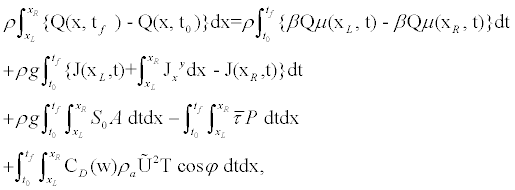
where Fx are the forces acting on the control volume (CV), νx is the velocity in the x -direction, d∀ is the volume differential, μ is the velocity vector and dA is the differential area taken as a vector normal to the control surface CS of the control volume. The first term on the right-hand side of equation (11) is the rate of change in momentum stored in the control volume and the second term is the momentum flux through the control volume. By moving the momentum stored in the control volume to the left-hand side and the sum of forces to the right-hand side and expanding the sum of forces, the conservation of momentum for the control volume becomes
 (12)
(12)
where S0 is the bottom slope of the channel,  is the average shear stress on the water from the channel boundary,
  is the wind induced shear stress on the water surface in the direction of the windvelocity vector, ρa is the density of air,
  is the wind velocity, CD(w) is the dimensionless drag coefficient for wind shear stress, and φ is the angle between the downstream flow direction in the channel and the velocity of the wind. Although complicated, equation (12) is a precise mathematical statement of the conservation of momentum principle. The friction force term simplifies if it is assumed that the relation between slope and boundary friction from steady uniform flow,
 (13)
(13)
can be generalized to unsteady flow by replacing the bottom slope S0, with the friction slope Sf given by relation (15). Applying this definition of the friction slope and dividing equation (12) by ρ yields the integral form of the conservation of momentum equation for open-channel flow. That is
 (14)
(14)
In equation (14), the momentum contribution from the lateral inflow is ignored. The friction slope must be estimated from the crosssectional characteristics and the flow. In terms of the total channel conveyance K, the friction slope is computed from

The use of the product Q |Q | instead of Q2 as normally seen in steady flow analysis gives the result that the friction is a retarding force on the water in the control volume for either direction of flow.
The differential form of equations derived by manipulating the integral form or an approximation of it by taking limits as the time and distance intervals approach zero. Approximating the integrals in equations (10) and (14) by finite differences and taking limits gives the following conservative system of time dependent partial differential equations
 (16)
(16)
where the wind stress terms are omitted in these developments to simplify the equations because these terms are not necessary for the general development of the differential equations of motion. In addition, the momentum flux correction coefficients β are assumed to be 1. Here r is the lateral inflow per unit length along the channel, defined as a function of distance and time such that
 (17)
(17)
The system of partial differential equations given by relation (16) is often called a 1-D complete shallow water problem with source terms. All the quantities in system (16) are algebraic expressions and can be positive or negative. Therefore, a negative outflow is an inflow. The first equation of system (16) is a statement of the conservation of mass principle (with ρ cconstant) on a per unit length basis. Similarly, the second equation of (16) is a statement of the principle of conservation of momentum per unit length. The terms involving derivatives of J on the right-hand side of the equal sign represent the net downstream pressure force per unit length. The derivative of μQ then moved to the right of the equal sign, represents the net efflux of momentum per unit length. Finally, the term gA(S0-Sf) is the net downstream force per unit length from gravity and friction forces.
Lemma 4.2.
The system of partial differential equations (16) is equivalent to the following conservative system

where  and
and  . Equation (18) emphasizes the conservative character of the system (16). Here,I1 represents a hydrostatic pressure force term as described in [23]
 (19)
(19)
in terms of the surface water level Y(x,t) and the breadth
 (20)
(20)
I2 accounts for the pressure forces in a volume of constant depth y due to longitudinal width variations
 (21)
(21)
In the particular case of prismatic channels of constant breadth (or top width), they reduce to the original equations
 (22)
(22)
Where
 and
and  (23)
(23)
Proof. The details of the proof is given in Appendix A.
In the particular case of prismatic channels of constant breadth (or top width), they reduce to the originale equations presented by St. Venant (for example [25], case where r=0). It is worth noting that they keep the nonlinear convective character and, therefore, admit discontinuous (weak) solutions [2]. In those cases in which F=F(U), it is possible to rewrite the conservative system in the form
 (24)
(24)
Where the Jacobian matrix J of the system (24) is given by
 (25)
(25)
where μ = Q/A is the cross section averaged water velocity and  is the celerity of the small amplitude surface waves. It is analogous to the speed of sound in gases and contains the essence of the compressibility associated to the deformability of the free surface. At the same time, it is the basis of the definition of the Froude number Fr=μ/c dimensionless number governing this kind of flow, which, also in analogy to the Mach number, allows for a classification in three flow regimes: subcritical (Fr<1) supercritical (Fr>1) and critical (Fr=1).
The system of equations (24) is a hyperbolic system of partial differential equations. Therefore, the Jacobian matrix J presents interesting properties closely linked to the physics of the problem represented by the mathematical model. The matrix can be made diagonal by means of the set of eigenvalues, which are real and represent the speed of propagation of the information. At the same time, the matrix has a set of linearly independent eigenvectors. The Jacobian’s eigenvalues can be obtained from det (J-λI2)=0 and are given by
 (26)
(26)
They represent the speed of propagation of the perturbations and hence are the convective wave velocities. If the Jacobian was a constant matrix, the system would be linear and decoupled. Being a variable matrix in terms of the dependent variables, the system is nonlinear and coupled, and the advection velocities can change of sign and value locally.
Lemma 4.3. The characteristic form of the system of equations (16) is obtained by transforming [8] the system of time dependent PDEs so that derivatives taken in the proper directions, called characteristic directions, can be written as ordinary derivatives and not partial derivatives. The result of this transformation is
 (27)
(27)
and
 (28)
(28)
Armed with the above tools, we describe in the subsequent sections the Lax-Wendroff scheme and we study in detail the stability of this algorithm.
In this section, we describe the Lax-Wendroff numerical scheme for 1-D complete surface water equations with source terms given by (16). This method seems to be the more convenient since it is one of finite difference schemes of second order accuracy for hyperbolic partial differential equations [26]. The development of this scheme for nonlinear PDEs follows from the Taylor series
 (29)
(29)
To approximate solutions of (22)-(23) (see appendix A) we discretize in both space and time assuming uniform mesh spacings of Δx and Δt, respectively. We denote the spatial grid-points by xj =jΔx and the time steps by tn =nΔt
Lemma 5.1. The Lax-Wendroff numerical scheme for 1-D complete Saint-Venant equations with source terms (22)-(23) is given by
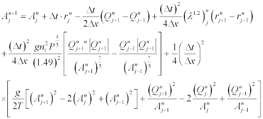 (30)
(30)
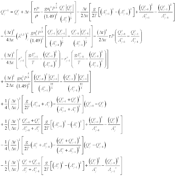 (31)
(31)
Proof. The proof of this Lemma is given in Appendix A.
Using Lemma 5.1 we are ready to analyze the stability restriction of the Lax-Wendroff scheme.
This section deals with the stability analysis of the Lax-Wendroff numerical scheme for 1-D complete shallow water equations with source terms in the case where the channel is prismatic. First, we present a rainfall hydrograph test, based on experimental measurements realized thanks to the SATREPS project METHOD in a flume at the rain simulation facility at Benoué-Garoua (Cameroon). The flume is 1150m long with a slope of 4%. The simulation duration is 40s. The rainfall intensity I(x,t)is described by
 (32)
(32)
For this test, as there is no rain on the last 150m, we have a wet/dry transition. The measured output is an hydrograph, that is a plot of the discharge versus time. The mathematical model for this ideal overland flow is the following: we consider a uniform plane catchment whose overall length in the direction of flow is L. The surface roughness and slope are assumed to be invariant in space and time. We consider a constant rainfall excess such that
 (33)
(33)
where I is the rainfall intensity and tf is the final time of the rainfall excess. According to relations (32) and (33) we assume in the following that r is more less that A and Q, i.e., r << A,Q . Furthermore, Lemma 4.1 gives the ”temporary” stability limitation of the Lax-Wendroff algorithm described in section 3.
Lemma 6.1. The numerical scheme (30) is stable if estimate (34) holds.
 ,
,
with the restriction:  . Here,
  and μ = Q/A .
Proof. Regarding the proof of this result we refer the readers in Appendix B.
In way similar, the following result gives the stability restriction of the numerical scheme (31).
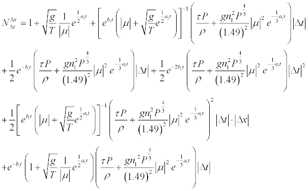
Lemma 6.2. The numerical scheme (31) is stable if estimate (35) holds.
 (35)
(35)
with the requirement:  Here,
Here,  and
and
 (36)
(36)
Obviously, 
Proof. The detail of the proof is given in Appendix B.
Now, using the above results (namely, Lemmas 4.1 and 4.2) we are ready to give the stability requirement of the Lax-Wendroff scheme (30)-(31) and to compare it with what is available in the literature (for example, Courant-Friedrich-Lewy condition for linear hyperbolic partial differential equations).
Theorem 6.1. The Lax-Wendroff scheme for 1-D complete shallow water equations with source terms (16) is stable if
 (37)
(37)
with the requirement:  : In relation (37):
  and
and  is given by relation (36).
Proof. The proof follows from both estimates (34) and (35). That is,
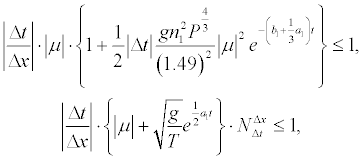 (38)
(38)
with the requirement:  . System of estimates (38) is equivalent to relation

In addition, it is obvious to see that estimate (39) holds
 (39)
(39)
Some important remarks on stability analysis
In the subsequent paragraphs we give some useful remarks on the stability restrictions obtained in this note and we compare it with what is known in the literature, for example, the Courant-Friedrichs-Lewy condition.
The stability restriction (37) shows that a small space step Δx forces the time step Δt to be more potentially small. This makes the Lax-Wendroff scheme extremely slow. For example, let us consider a spatial domain [0; 1] with space step Δx=5.10-2 Then, the required time step (Δt)req must be less than the maximum solution (in modulus) of equation:  . More especially, since
  , the required time step (Δt)req must be less or equal than
  .
.
The Lax-Wendroff scheme (30)-(31) for 1-D complete surface water equations has stability restrictions (34)-(35) that limit the maximum time step. The stability requirement given by estimate (37) does not coincide with the famous Courant-Friedrichs-Lewy (CFL) condition obtained for simple hyperbolic partial differential equations (for example: linear advection equation, wave equation, burgers equations, etc...) because the Lax-Wendroff scheme is applied to a more 1-D complex unsteady partial differential equations. As discussion on the stability restrictions one can refer to the stability analysis of the two step Lax-Wendroff method and the MacCormack scheme applied to complete burgers equations [26]. However, it is easy to show that the greatest eigenvalue (in modulus) λmax of the Jacobian matrix J of conservative system (18) is bounded by the positive quantities  and
and  . Thus it is obvious that inequality (40) holds
 (40)
(40)
which means that the stability limitation given by (37) controls the CFL condition, and so it is more restrictive. The stability restriction (37) is highly unusual. Since we normally find condition (37) from a Fourier stability analysis, it follows from estimate (40) that an instability occurs when |Δt| is greater than some |Δt|max which can be viewed as (Δt)req As observed in proving Lemmas 4.1 and 4.2, it was not easy to obtain the stability criterion for the Lax-Wendroff scheme applied to 1-D complete Saint-Venant equations (16). However, it follows from conditions given by relations (36) and (37) that the empirical formula
 (41)
(41)
can be used with an appropriate safety factor. The latter formula (41) reduces to the usual inviscid condition  (case where the right-hand side of equation (16) is assumed equals zero) when
  is set equal to 1. It should be remembered that the ”heuristic” stability analysis, i.e., equation (37), can only provide a necessary condition for stability. Thus, for some finite difference algorithms, only partial information about the complete stability bound is obtained and for others (such as algorithms for the heat equation) a more complete theory must be employed.
• Once the stability is assumed the Lax-Wendroff scheme is both convergent and an explicit one step two time level method.
• Relation (37) illustrates the effect that the choice in both space step and time step have on the stability of the Lax-Wendroff scheme.
In this section we simulate the Lax-Wendroff scheme described in section 4 for 1-D complete shallow water equations with source terms. We focus on a practical application of a shallow water flow based on the Benoué river. This river is a 7000m long reach of the upstream part (altitude=174.22 m) and it is located in Cameroon. Being a mountain river, it is characterized by strong irregularities in the cross section, by a rather steep part in the first kilometers and by a low base discharge (708m3/s) which, altogether, produce a high velocity basic flow, transcritical in some parts. More specifically, we consider the problem of floods observed in this river in 2012 because it is a classical example of time dependent nonlinear flow with shocks to expect floods and to test conservation in numerical schemes. Furthermore, we assume that this model is generated by the 1-D complete shallow water equations with source terms for the ideal case of a flat and frictionless channel with prismatic cross section, i.e., constants top width (T=348m) and wetted perimeter. (P=366.4m) Using the initial data provided by the river:  and A(0,t0=200)=635.8 straightforward computations show that the initial conditions are defined as follows
 (42)
(42)
where t0 is the initial time (t0=200s), A(x,t) is the area of cross section and Q(x,t) is the discharge.
The calculation times used are so as to avoid the interaction with the boundaries of the channel. So the boundary conditions are given by

and

Indeed, the study is done in the channel on 4 October 2012 and whose the purpose is to expect floods in the next years. Although the problem is defined by a system of shallow water equations with source terms, it is considered as a system of hyperbolic partial differential equations and can serve as a standard test case for validation of schemes whenever an analytical solution is known. Starting from initial and boundary conditions given by still water, the theory of characteristics can supply an exact evolution solution [27] that can be used as a reference. In the example presented, when using the initial and boundary conditions given by relations (42), (43), and (44), simple calculations yield the values of parameters a1, a2, b1, b2, tf, L, Kλ, defined in section 4, i.e.,
 , a2 = b2 =π ≅ 3.1416 ,
  , k =2 π ≅ 6.28 m and
  , where t0=200S is the initial time, tf is the final time, Kλ is the wave number, and
  is the time interval length. Using the definition of Q(L,t0) together with the boundary conditions we have
  , so we can take L=1000m where L is the rod interval length for the ideal case of a flat and frictionless channel with prismatic cross section. In addition, the averaged shear stress is assumed equals zero, i.e, τ=0, the manning’s number (n1) equals 0.025s m1/3 , and the rainfall intensity I(x,t) is described according to relation (32), i.e.,

where I is the rainfall intensity defined by relation (45), t0 =200S and tf =240S are initial and final time, respectively, of the rainfall excess computed above, and L=1000m is the rod interval length. The approximate solutions given by numerical schemes (30) and (31) obtained from 20 to 10850 iterations, respectively, are displayed in Figures 1 and 2. Using the experimental values of parameters a1, a2, b1, b2, P, T, n1 and g, computed above one easily shows, according to relation (36) that  for all values of Δt an
 d Δx satisfying Δt,
  and , for all t∈[200;240] . Different values of k=Δt=8.2×10⁻⁴S, k=Δt=8.2×10⁻³S and k=Δt=8.2×10⁻²S numbers obtained from (37) as the steady flow cases and both space steps of Δx=5m, Δx=2×10⁻¹m and Δx =10-1m in the mesh are used. Before 200 iterations are encountered, the discharge wave propagates with almost a perfectly constant value at different times (Figures 1 and 2). Further, after 200 iterations are encountered, the discharge wave also destroys at different times (Figures 1 and 2). So, the graphs show that the solution of the difference equations may grow with time (for example, Figure 1 (test 5) and Figure 1 (test 3)) and still satisfy the Von Neumann necessary condition. On the other hand, we obtain similar observations for the cross section. Furthermore, the figures indicate that the cross section starts to destroy after a fixed time and can become negative. Moreover, combining the different values of Δx and Δt we observe from the figures that the cross section also can become negative if the ratio
  is less than 1.64×10⁻³. Thus, it is not hard to see that good solutions are obtained for a small time step Δt and a mesh size Δx satisfying the stability limitation (37) along with the estimate
  Physical insight must be used when the stability limitation (37) of the Lax-Wendroff method is investigated. Finally, the figures show that the solutions do not increase exponentially with time. More specifically, they indicate that stability for the Lax-Wendroff scheme is subtle. It is not unconditionally unstable, but stability depends on the parameters Δx and Δt as show Figures 1 and 2. We conclude that the numerical examples indicate the crucial role played by the ratio
Similarly, the MacCormack method which is a predictor-corrector version of the Lax-Wendroff scheme provides a reasonably good result at discontinuities. This method is much easy to apply than the Lax-Wendroff scheme because the Jacobian does not appear. The amplification factor and stability requirement almost are the same as presented for the Lax-Wendroff method [26] case of inviscid burgers equation). It is important to note that the solutions obtained for the same problem at the same courant number are different from those obtained using the Lax-Wendroff scheme. This is due both to the switched differencing in the predictor and the corrector and the nonlinear nature of the governing PDE. One should expect results that show some differences, even though both methods are equivalent for linear problems. In addition, it should be noted that reversing the differencing in the predictor and corrector steps leads to quite different results. The best resolution of discontinuities occurs when the difference in the predictor is in the direction of propagation of the discontinuity [26]
In this paper, we have presented a mathematical model of 1-D complete shallow water equations with source terms and we have described the Lax-Wendroff scheme for these hyperbolic partial differential equations in the case of a prismatic channel. The stability analysis of the method is also considered and deeply studied together with some numerical experiments. From this analysis it follows that while the stability limitation is highly unusual, the result has a potential positive implication since the stability requirement presented in this work controls the famous Courant-Friedrich-Lewy condition which is well known in the literature. In the future, the following problems will be subject of our investigations.
1. Stability analysis and second order accuracy of the Lax- Wendroff scheme for 1-D complete shallow water problems in an open channel;
2. Stability analysis of two steps explicit MacCormack scheme for 1-D complete Saint-Venant equations with source terms in the case of a prismatic channel;
3. Analysis of stability and second order accuracy of two steps explicit MacCormack method for 1-D complete shallow water problems with source terms in the case of an open channel.
The authors appreciate the contribution of the editor and anonymous referees whose valuable and thoughtful comments have led to significant improvement of this work.
\begin{figure}
\begin{center}
Cross-section and Discharge profiles corresponding to Δx=5m and Δt=8,2.10-4S
\begin{tabular}{c c}
\psfig{file=fig1laxwend.eps,width=8cm}& \psfig{file=fig2laxwend.eps,width=8cm}\\
0≤ x (m) ≤ 103 & 0≤ x (m) ≤ 103 \\
\end{tabular}
\vskip 1cm
Cross-section and Discharge profiles corresponding to Δx=5m and Δt=8,2.10-4S \begin{tabular}{c c}
\psfig{file=fig3laxwend.eps,width=8cm}& \psfig{file=fig4laxwend.eps,width=8cm}\\
0≤ x (m) ≤ 103 & $ 0≤ x (m) ≤ 103 \\
\end{tabular}
\end{center}
\caption{Cross-section (in green) and Discharge (in blue) profiles obtained from the Lax-Wendroff scheme for 1-D complete
shallow water flow in a prismatic channel.}
\label{figure 1}
\end{figure}
\begin{figure}
\begin{center}
Cross-section and Discharge profiles corresponding to Δx=2.10-1m and Δt=8,2.10-2S
\psfig{file=fig5laxwend.eps,width=8cm}& \psfig{file=fig6laxwend.eps,width=8cm}\\
0≤ x (m) ≤ 103 & 0≤ x (m) ≤ 103 \\
\end{tabular}
\vskip 1cm
Cross-section and Discharge profiles corresponding to Δx=2.10-2m and Δt=8,2.10-3S
\begin{tabular}{c c}
\psfig{file=fig7laxwend.eps,width=8cm}& \psfig{file=fig8laxwend.eps,width=8cm}\\
0≤ x (m) ≤ 103 & 0≤ x (m) ≤ 103 \\
\end{tabular}
\end{center}
\caption{Cross-section (in green) and Discharge (in blue) profiles obtained from the Lax-Wendroff scheme for 1-D complete
shallow water flow in a prismatic channel.}
\label{figure 2}
\end{figure}
Appendix A
This part considers the proofs of Lemmas which have helped to analyze the main result presented in this report.
Proof. (of Lemma 4.2.)
Manipulating the integral form of the equations or an approximation of these equations and taking time intervals and distance close
to zero, omitting the terms of the wind force in order to simplify the equations and setting the flux dynamic correction coefficients
β=1 one obtains the differential form of conservative equations given by (46)
 (46)
(46)
According to relation (9) of Lemma 2.1, one has  , So, the system of equations (46) yields
 (47)
(47)
Differentiating the function I1 given by relation (19) (by use of the Leibniz rule [28]) with respect to the spatial variable and using
relation (21) yields
 which implies
Replacing  and μ by
  and Q/A, respectively, in the system given by relation (47) yield the result.
On the other hand, it follows from relation (8) of Lemma 4.1 that
 (48)
(48)
Since we are working in the particular case of a prismatic channel then  , which implies
  . Substituting this in (48)
results in  . So, the system of equations given by (47) becomes
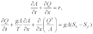 (49)
(49)
which is equivalent to
 (50)
(50)
Now, let us prove Lemma 3.1.
Proof. (of Lemma 3.1.) A combination of relations (22) and (25) yields
 (51)
(51)
In addition
 (52)
(52)
Partial derivatives with respect to time of relations (51) and (52) provide
 (53)
(53)
On the other hand
 (54)
(54)
where λ1,2 represent the eigenvalues of the Jacobian matrix J and are given by relation (26). So
 (55)
(55)
Combining the Taylor series (29) and both relations (52)-(53), straightforward computations give
 (56)
(56)
Since the Lax-Wendroff scheme is a second order scheme, the term  is approximated by using the central difference, i.e.,
  . Furthermore, the central difference for the source term gives
  Putting G=JS results in

In way similar
 (57)
(57)
Setting  and
and  , we have that
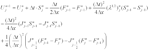
Recall that  and letting
  yields
  where
where  In addition,
  and
and  and
and  . Since
  , putting
  , the vector F becomes
  , using this we have
  , where
  On the other hand, it follows from relation (12) that
  , hence
  , where
  and
and  . A simple multiplication (matrix and vector) yields
  . Letting
  , one has
  So,
So,
 (58)
(58)
Where
 (59)
(59)
Furthermore, setting 
 (60)
(60)
with
 (61)
(61)
and
 (62)
(62)
a combination of relations (60)-(62) gives
 (63)
(63)
Combining relations (58), (59) and (26), with  , , we have
 (64)
(64)
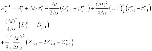 (65)
(65)
and
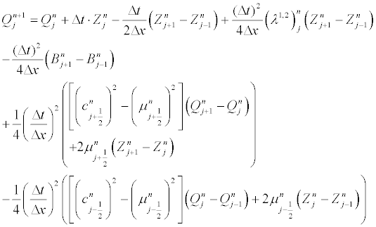
Closed form expressions of some terms
It follows from relations (13), (15), and (4) that 
where  is given by Definition 2.6, n1 is the Manning’s roughness coefficient, and τ is the shear stress. In addition, replacing K
and R by their values in relation (15) yields
 (67)
(67)
It follows from relations (13) and (67) that
 (68)
(68)
After straightforward computations, it follows from relation (67) and (68) that
 (69)
(69)
 (70)
(70)
 (71)
(71)
 (72)
(72)
and
 (73)
(73)
In addition, relation (61) yields
 (74)
(74)
So, the result follows from relations (69) to (74).
Appendix B
Below are the proof of both Lemmas 4.1-4.2. We start with the proof of Lemma 4.1. In the following C designates the set of complex
numbers while ℜ represents the set of the real one.
Proof. (of Lemma 4.1). Using relation (30), setting  and
and  (where a,b∈C and K is the wave length), then
  and
and  . In all this proof we consider the algebraic forms of complex numbers a and b i.e., a=a1+ia2
and b=b1+ib2. By straightforward computations we have,
 (75)
(75)
 (76)
(76)
and
 (77)
(77)
It follows from relations (76) and (77) that
 (78)
(78)
On the other hand, it is easy to see that

where the last equality of (79) follows from the equality:  for all
In way similar, simple calculations give

Setting  , a combination of relations (75), (78) and (79) provides
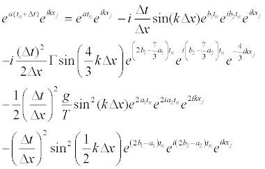
Dividing both sides of relation (80) by eatn eikxj , one obtains the amplification factor
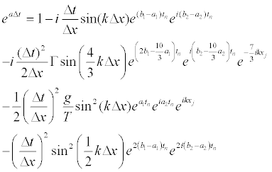
Putting
 ;
; 
 and
and 
where


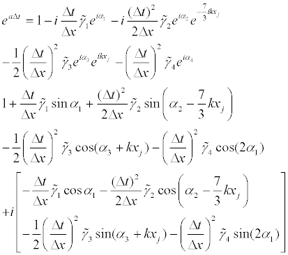
and using relation (81) the amplification factor becomes
Of course the aim of this report is to give the general picture of stability restrictions. Since the formulae can become quite heavy, for
the sake of simplicity, we consider in all the proofs the following remark which plays a crucial role in our study.
Remark 6.1. It is well known in the literature [26,10-12]) that for certain hyperbolic problems the diffuse effect is not much of an
issue since for those problems one is interested in the case where KΔx<<1.
According to remark 6.1 we assume that
 and we neglect the terms
of the form  and those of the form
  with respect to sin(βΔx) i.e.,
  , where f(x) and g(x) are functions of sin(β1Δx) and cos(β2Δx) (with n,m∈ N \ {0} and 1 2 β ,β ∈ℜ ). In other words, we need only retain the terms of first order in sin(βΔx) (with β ∈{k,4k 3,k 2} .
This fact along with relation (82) show that the squared modulus of the amplification factor is approximated by
 (83)
(83)
Using approximation (83), it is not hard to see that the numerical scheme (30) is stable if
 (84)
(84)
which is equivalent to write
 (85)
(85)
Estimates given by (85) are satisfied if relation (86) holds
 (86)
(86)
with the restriction :  . Since
  then
then
 (87)
(87)
So, the proof of Lemma 4.1 is completed thank to relations (86) and (87).
Now, let us prove Lemma 4.2.
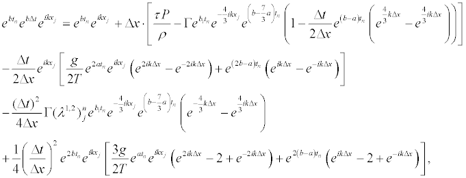
Proof. (of Lemma 4.2.) In all this proof, we consider the hypothesis r << A,Q , (where r is the rainfall excess given by (33)). As
already mentioned above, we recall that  , where k ∈ℜ is the wave length number and a,b∈C . So,
 (88)
(88)
where 
Dividing both sides of (88) by  and replacing
  by
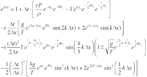
by  , a straightforward calculation provides the
amplification factor
 (89)
(89)
Designating by
 (90)
(90)
where

and

in way similar
 (91)
(91)
with

and

 (92)
(92)
Where


with  and
and
 (93)
(93)
Where

and

a combination of relations (90), (91), (92) and (93) gives

 (94)
(94)
So, using relation (94), the squared modulus of the amplification factor is given by

According to remark 6.1 we assume that  with
with  and we only need retain the terms of first
order in sin(βΔx), where  . Using this together with relations (90)-(93) and (95), the squared modulus of the
amplification factor becomes
 (96)
(96)
On the other hand, on account of equality  , straightforward computations yield
 (97)
(97)
 (98)
(98)
 (99)
(99)
Using approximation (96) the numerical scheme (31) is stable if
 (100)
(100)
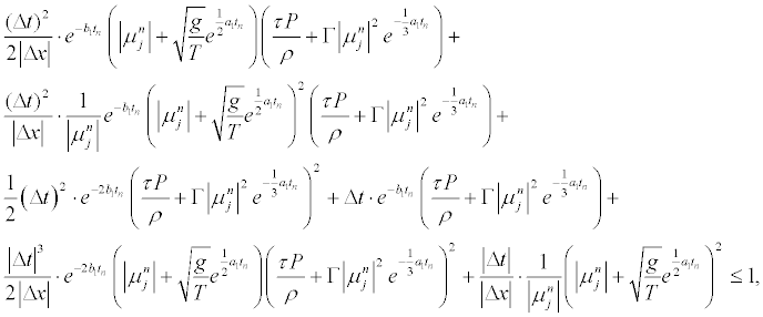
A combination of relations (97)-(100) gives estimate (101)
 (101)
(101)
where the following majorations were used:
 (102)
(102)
 (103)
(103)
So, the proof is completed thanks to estimates (101)-(103).