Journal of Osteoporosis and Physical Activity
Open Access
ISSN: 2329-9509
ISSN: 2329-9509
Research Article - (2015) Volume 3, Issue 2
Robotically-assisted surgical system is introduced to achieve safety and high accurate operation. However, its fixation to the patient’s bones requires bone stiffness and there are some problems to apply brittle or cracked bones such as in rheumatism. Metal pin screws are commonly used to connect a robot and a patient and not safe for brittle bones. In this research, we focus on the optimization of a body-mounted small robot system that assists spine puncture surgeries. The robot consists of a fixation part and a needle guide part. The fixing unit can be controlled the stiffness to contour the patient’s body surface tightly. At first, it deforms freely to conform to the surface of the target, and then transition to solid-like state to save the deformed shape by utilizing the jamming transition phenomenon. The guiding part employs a double 45˚ gear mechanism and designed to locate the three cylinder-shaped motors in parallel. It achieved 4-degree-of-freedom needle guidance, X-ray-transparent views in the surgical area and downsizing.
The fixing device is designed to be attached firmly to the human body with keeping the gravity center of the surgical assistance robot low. We designed tripod stand fixing device that can circumvent the unsuitableness area of the human back. The performance of the fixing device on a soft tissue is evaluated. The force to insert a needle into a porcine soft tissue was measured to evaluate the required strength for needle insertion. To penetrate the 30-mm-thick soft tissue, required force was 7.7 N in RMS (Root-mean-square). The fixing stability and the accuracy of needle guide was evaluated by measuring the displacement during needle inserting operation. The displacement to penetrate the 30-mmthick soft tissue was 1.13 mm and 0.38˚ in RMS. Finally, we evaluated the result of the fixing device on human shape target. The displacement of the fixing device on a soft tissue by the external force of needle inserting operation was measured. The displacement of the fixing device on a human shape phantom by the external force of needle inserting operation was 0.13 mm and 0.06˚ in RMS. The total displacement of needle guide was 0.73 mm and 0.59˚ in RMS.
<Keywords: Surgical robot; Percutaneous surgery; Bone fragility; Bone fixation; Body-surface fixation
The surgical robotic system works as the additional hand of surgeons or expansion of manual movement. The robot performs a surgical procedure with a high degree of accuracy. In the field of orthopedic surgery, surgical robotic systems such as ROBODOC [1] and Renaissance [2] have developed and are in widespread clinical use. These program-controlled robots works accurately through the use of the geometrical information of a surgical robot and a patient’s affected area that are acquired by medical image modality. Precise operation of surgical robots is premised on that the geometrical relationship between a surgical robot and a patient is maintained during surgery. The fixation between a robot and a patient is commonly achieved by metal pin screws that are inserted into patient’s bone. The metal pin connects a surgical robot to patient body during surgery. This method is used because bone is one of hard organs in the human body and useful as the place for fixation. Stationary clamp also can be used to connect a bone and a surgical robot. However, to grip a bone inside of a human body, a large sectioning is necessary to approach the surface of bone and invasiveness is increased. Thus, metal pin screws are conventionally used for a surgical robot system. Even though, metal pin fixation is not optimal method for a surgical robot. In the case of minimally invasive surgery, the amount of invasiveness of fixing pin is relatively large. For instance, puncture surgery is one of the minimally invasive surgeries. A surgeon operates percutaneous puncture with seeing the intraoperative X-ray photograph of the operative field. When comparing the invasiveness of puncture and fixing pin insertion for soft tissues and bones, the extent of latter cannot be ignored. In particular, when a patient develops osteoporosis or rheumatism, the Young’ modules and yield stress of bones decrease and destruction of bones tends to take place. Some small cracks and regional brittleness of bones also results in concentration of stress and bone fracture. Metal pin fixation is not optimal for patients because of not only the invasiveness for a patient’s soft tissues but also a great burdens on a patient’s bone.
A non-invasive fixing method: body surface fixation is introduced for each surgical robot developed by Walsh et al. [3] and Maurin et al. [4]. These robots are developed for a puncture surgery such as biopsy. The fixation between a surgical robot and a patient is achieved by a belt. However, its fixing performance was poor, due to easily sideslip. To achieve rigid fixation of a surgical robot to a patient’s surface, suction unit is one of the best methods. The suction unit works when the unit adheres tightly to the object’s surface. By vacuuming air from the enclosed space between the suction unit and the object, the suction unit is pressed into the target by atmosphere pressure. The fixation of suction unit is achieved by the air pressure and sideslip is prevented by the friction force between the suction unit and the target.
To utilize the suction device for the fixing device, the device has to contour a patient surface and becoming undeformable in the act of fixation. Tailor-made template [5] is one of the solutions to introduce an individualized fixing device. However, it takes time and financial cost to fablicate the tailor-made fixing device. In this research, we use the jamming transition phenomenon. This phenomenon is a phase transition from fluid-like to solid-like condition of the particle system. The phenomenon is controlled by increasing the density of particles. This phenomenon is adequate for the use on the body surface, because it can be controlled in a moment without reaction heat.
In this research, we developed a small surgical robot that assists spine puncture surgery, because spine surgery is one of the operation that require high accurate operation to achieve good surgical result. The incidence rate of vertebral body fracture increases with ages [6]. The basic treatment for vertebral fracture is conservative therapy with a corset. However, if the patients wear a corset at an old age, the risk of spine deformity and weakness of muscle increase. Thus, surgical therapy is selected for treatment. Recent years, percutaneous vertebroplasty is seleted to treat the fracture spine bone. For this surgery, a surgeon has to drill and penetrate puncture needle accurately. Conventionally, surgeons insert the surgical tool with half an eye on an intraoperative X-ray view. The required accuracy of the needle puncture is 3 mm and 3 degree in ptactice. To improve the surgical result, it is important to lead to great accuracy in operation. For this purpose, the acurate movement of surgical robotic system is adequate. Thus, we propose a surgical robot. The robot is composed by the driving parts that guide position and orientation of needle guide that assists needle puncture and the fixing device that connect the robot and the patient body surface. The guiding part has the X-ray transmission region at the center for the intra-operative X-ray view of the affected area. To ensure this region, actuators are separated from the center of the guiding part. The fixing device is attached bottom of the guiding part. It can contour the shape of a patient’s and transition to solid-like state to work as a sucking fixation device. We optimized the fixing device and evaluated the performance of the surgical robotic system.
The proposed device is applied to assist the spine puncture surgery as the percutaneous vertebroplasty as already stated. Referring to the methods of Koizumi [7], the procedure of the operation is given below. First, the patient’s vertebra is identified by using X-ray images. Next, an angle of needling is decided. Next, puncture needle is inserted under anesthesia. After puncturing, bone cement (such as polymethylmethacrylate) is injected into the vertebra. The function of our proposed device is to display the correct position and direction of puncture needle at the moment of needling. Thus, the geometrical stablity of the device on the body is necessary for our fixing device. To achieve high arrurate operation, we challenged to develop a device that adequately satisfies the required accuracy.
Spine punctures assistance robotic system
The needle guide control part for spine puncture surgery is overviewed as shown in Table 1 and Figure 1. It controls 2-degree-offreedom (2 DOFs) for position and 2 DOFs for orientation of a surgical tool. The robot consists of a orientation control part and a position control part. We designed spherical coordinate system of two crossing curved guides. α and β axes are coplanar and the intersection of these two axes is a pivot point of needle guide. According to the study of Chaynes [8], the transverse pedicular angle of spinal bone is ? 31° and the sagittal pedicular angle is ? 25° to a median position. Therefore, the angle of needle insertion is about 30 degrees [8] to a median position. α and β axes have to rotate more than 30 degrees. Because the distance from a pedicle of vertebral arch to the fixed-point of the crossing curced guides is about 100 mm, the required range of movement is defined as 30 mm to control the position of fixed-point. Actuators are separated from the curved guides, and the orientation control part is detachable. 45 degrees bevel gears are applied to transmit the rotation of the actuator to α and β axes. Actuators of α, β, t axes are located at the bottom of the needle guide control device with same directions to maintain low center of gravity and compactness. Because the largest part of lumber spine is L5 and the width of that is 52.2 ± 5.1 mm [9]. Thus, a hole of 70 mm in diameter is made at the center of the position control part for the X-ray view. Currently, curved guides and needle guide are fabricated with acrylic resin (Vero Clear, Stratasys Ltd.) by 3D printer (Objet CONNEX 500, Stratasys Ltd.). Hubell [10] showed the data of X-ray attenuation coefficient. The attenuation coefficient of acrylic resin ([CH2C(CH3)(COOH3)]n) is 0.248 cm-1 at the condition of 50 keV. When the thickness of the acrylic resin is 5 mm, the transmission of X-ray is 88 % and doesn’t disturb X-ray viewing.

Table 1: Mechanical specification of needle guiding device.
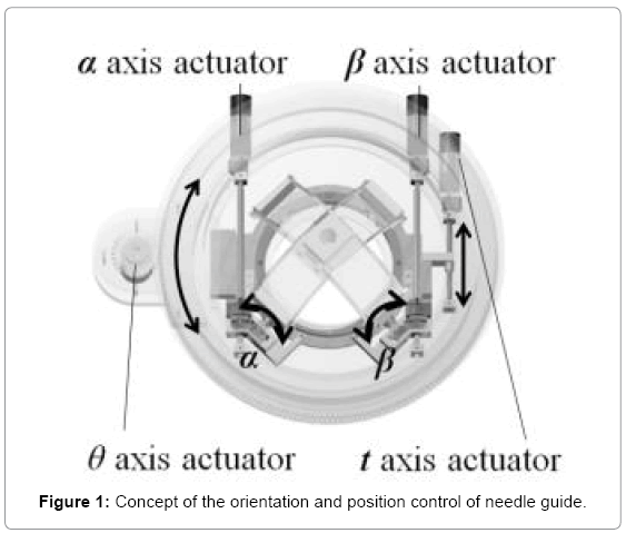
Figure 1: Concept of the orientation and position control of needle guide.
The orientation of needle guide is described as
 (1)
(1)
The position of the pivot point is controlled t and θ axes. The position is described as
 (2)
(2)
And the pathway of puncture needle is described as (3) by using an intervening variable n
 (3)
(3)
Where (image) is the pathway of a puncture needle.
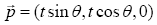
The proposed fixing device contour the shape of a patient’s body and is affixed to the body surface. The fixing device is composed of elastic container and fluidized particles. The container and particles’ aggregate deforms freely when the device is compressed to the target. After optional deforming, the device changes the hardness by incorporating jamming transition phenomenon. The hardened fixing device works as suction unit that fits the shape of patient’s body surface.
The process of fixation is shown in Figure 2. First, we ready the device above the target. Air pressure values inside and outside of container are almost same and the density of particle is low. The fixing device contains fluid-like-state particles and deforms easily. Next, we press the device against the target and start vacuuming from the suction ports. Inside of the elastic container, the air is decreased and the density of particles becomes high. The phase transition of the particles starts when the device keeps in close contact with the target and the vacuum pad becomes functional. Finally, the device that finishes contouring to the surface of the target hardens. The design of the device enables it to be strongly affixed to the surface of a target by the suction force.
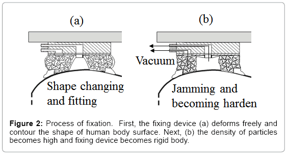
Figure 2: Process of fixation.First, the fixing device (a) deforms freely and contour the shape of human body surface. Next, (b) the density of particles becomes high and fixing device becomes rigid body.
Optimization of the fixing device
To introduce body surface fixation, the consideration for the shape of body is important factor. Thus, the design of the robot and fixing device should be optimized for a human back. In this research, we referred AIST/HQL measure of human body and shape data base 2003 [11]. The dimensional data of Figure 3 (a) chest breadth, (b) waist breadth and (c) waist belt are listed in Table 2. Thus, the width of the body-mounted surgical robot should be about 250 mm, because the robot should not interrupt approximation of a surgeon to a patient.
Figure 3: Definition of measurement parameter. (a) Chest breadth, (b)Waist breadth and (c)Waist belt.
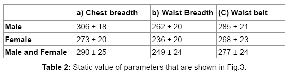
Table 2: Static value of parameters that are shown in Fig.3.
The fixing device can be affixed to the body surface when the proposed device adheres to a patient’s body surface. Thus, adequate amount of deformation margin is required for the proposed device. However, if the device is unnecessarily thick, the distance from the affected area to the surgical robot on the fixing device increases and the surgical precision is reduced. So, the design of the fixing device should be optimized: as thin as possible.
The main affected area of spine puncture surgery is a lumbar spine that exists between costal bone and iliac bone. To analyze the shape of the body surface around a lumbar spine, we extract 200 mm diameter area that includes a lumbar bone and develop an adequate design of the fixing device. The subject of this analysis is AIST/HQL measure of human body and shape data base 2003 and it contains 49 males and 48 females datasets.
The difference in height of body surface was evaluated by the following process. First, a plane fitting is applied to the extracted 200 mm diameter area (Figure 4). The plane doesn’t bisect with a body surface. The normal direction of fitted plane is the direction of approach.
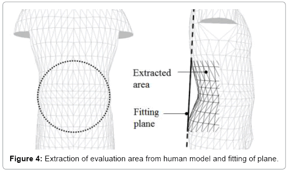
Figure 4: Extraction of evaluation area from human model and fitting of plane.
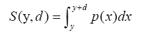
To evaluate the amount of area that d thickness fixing device can contour, we extracted the area of a body model that exist within a range of d from the fitted plane (Figure 5(a)). When the amount of area that exists at a distance of x from the fitted plane is p(x), the summation of contouring area S(d) is calculated by equation (4).
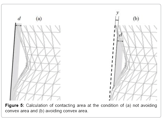
Figure 5: Calculation of contacting area at the condition of (a) not avoiding convex area and (b) avoiding convex area.
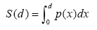 (4)
(4)
Next, we evaluated the relationship between the thickness of the fixing device and the contacting area when the fixing device avoids the convex shape (Figure 5(b)). When the thickness of the fixing device is d and the fixing device is moved y mm closer to the body surface, the summation of contouring area is S(y,d). The best approach distance y is calculated by equation (5) and (6).
 (5)
(5)
 (6)
(6)
We evaluated the amount of contacting area when the thickness of the fixing device is d = 5, 10, 15, 20, 25, 30 and 35 mm.
We measured the contacting area of each subject when the contouring area S(y) or S(y,d) are 25%, 50% and 75% of the total area on the subject’s surface. From 49 males and 48 females, we calculated the contact probability
Implementation of fixing device
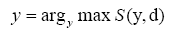
When the fixing device contours the area that includes convex shape of a body surface, the result of evaluation is shown in Figure 6. If the initial thickness of the fixing device is increased, the contacting area also become increased as Figure 7 and 8, because the area around a lumbar spine is concaving relative to the surrounding area. When the fixing device is selectively affixed to the no convex area of a body surface, the result of evaluation is shown in Figure 9. If the initial thickness of the fixing device is increased, the contacting area also become increased as Figure 10 and 11. By avoiding convex area, the required thickness of fixing device decrease. Thus, the fixing device should be designed to avoid the convex area. In this situation, the thickness of the fixing device is kept as low as possible.
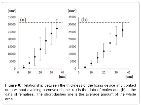
Figure 6: Relationship between the thickness of the fixing device and contact area without avoiding a convex shape. (a) is the data of males and (b) is the data of femaless. The short-dashes line is the average amount of the whole area.
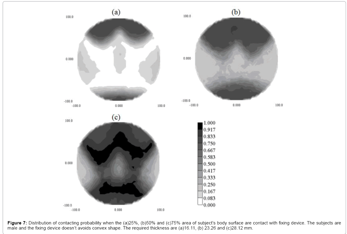
Figure 7: Distribution of contacting probability when the (a)25%, (b)50% and (c)75% area of subject’s body surface are contact with fixing device. The subjects are male and the fixing device doesn’t avoids convex shape. The required thickness are (a)16.11, (b) 23.26 and (c)28.12 mm.
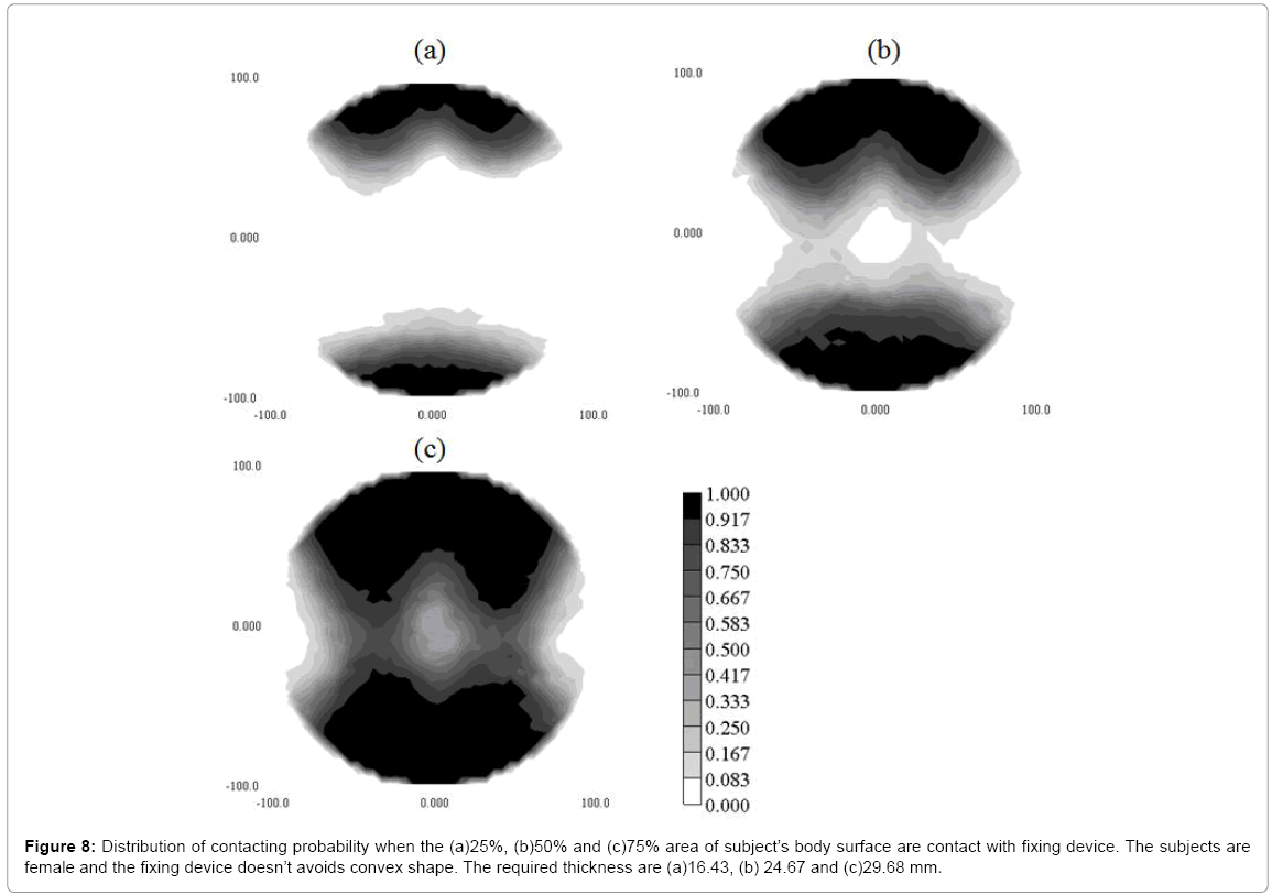
Figure 8: Distribution of contacting probability when the (a)25%, (b)50% and (c)75% area of subject’s body surface are contact with fixing device. The subjects are female and the fixing device doesn’t avoids convex shape. The required thickness are (a)16.43, (b) 24.67 and (c)29.68 mm.
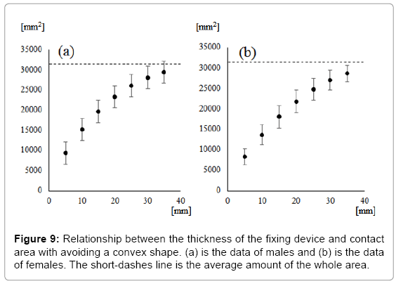
Figure 9: Relationship between the thickness of the fixing device and contact area with avoiding a convex shape. (a) is the data of males and (b) is the data of females. The short-dashes line is the average amount of the whole area.
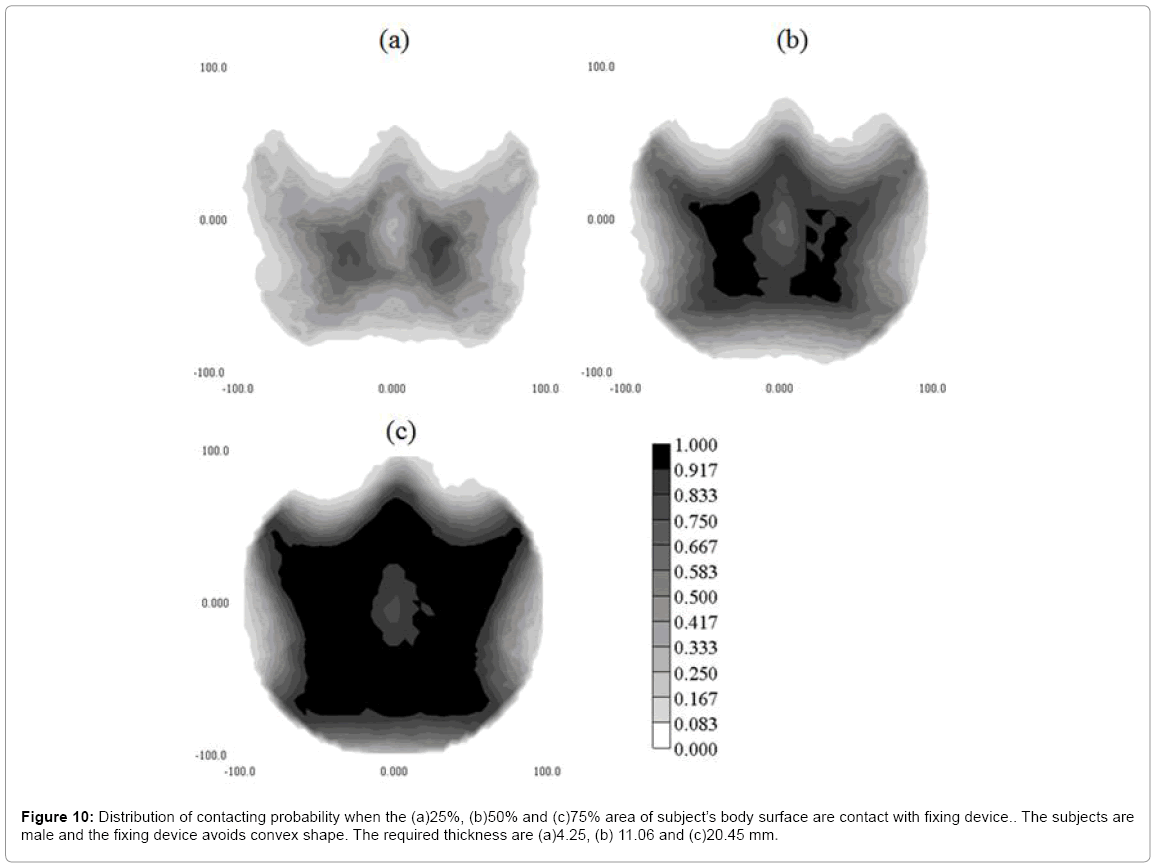
Figure 10: Distribution of contacting probability when the (a)25%, (b)50% and (c)75% area of subject’s body surface are contact with fixing device.. The subjects are male and the fixing device avoids convex shape. The required thickness are (a)4.25, (b) 11.06 and (c)20.45 mm.
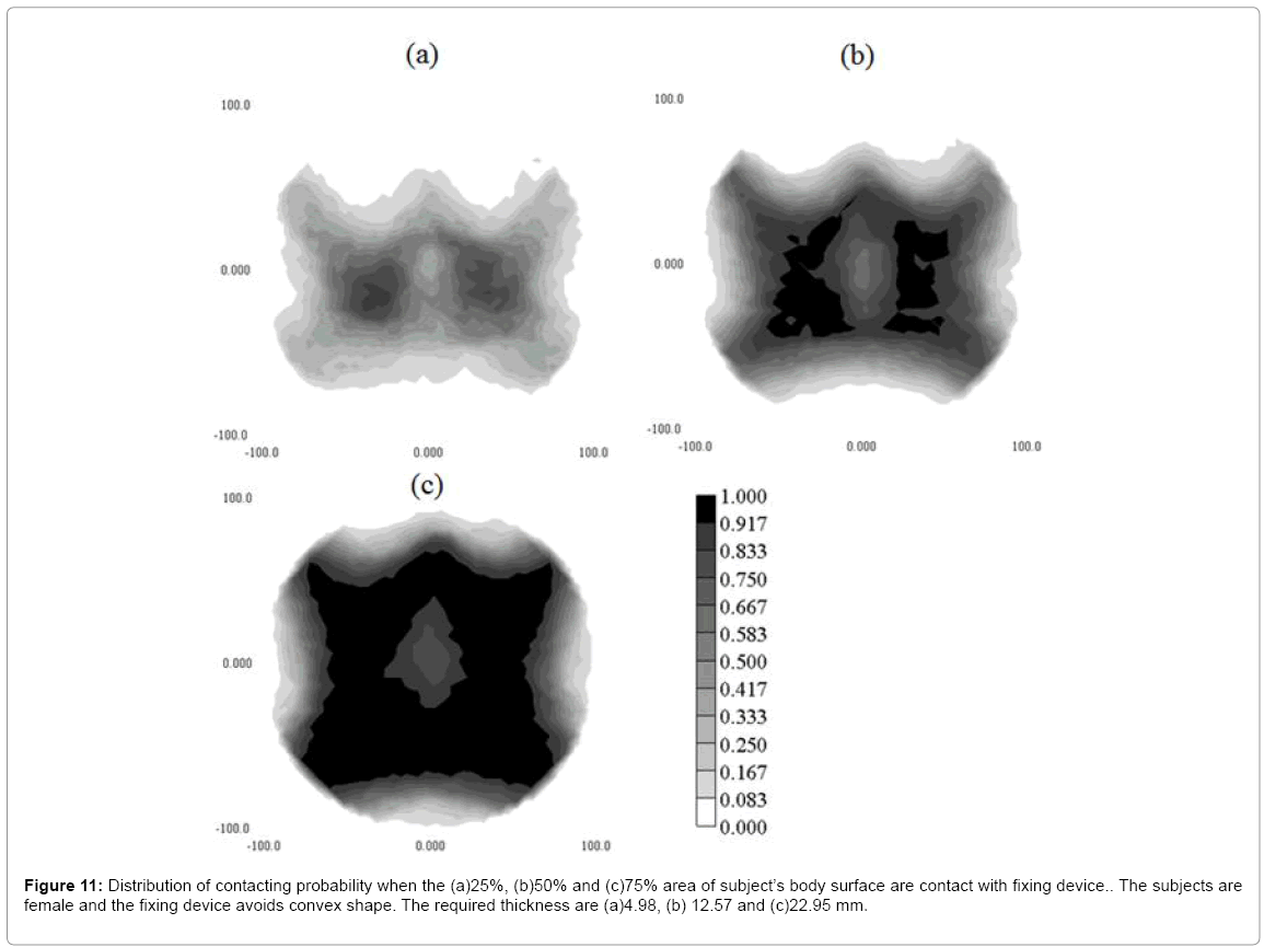
Figure 11: Distribution of contacting probability when the (a)25%, (b)50% and (c)75% area of subject’s body surface are contact with fixing device.. The subjects are female and the fixing device avoids convex shape. The required thickness are (a)4.98, (b) 12.57 and (c)22.95 mm.
To stabilize the fixing device in three dimensional space, more than three fixed points are required. Thus, we designed the tripod stand fixing device that can avoid convex part of a body surface. The initial thickness of the fixing device was set as 25 mm (deformation margin is 20 mm and air flow part is 5 mm), because 75 % of body surface can be used as fixing area when the thickness of the fixing device is 20 ~ 25 mm as shown in Figure 10 and Figure 11. The design of the surgical robot system for spine puncture surgery is shown in Figure 12. The fixing device is composed of a deformable pad that works as a sucking unit. The sealing gel that surrounds the external frame of the suction pad is a non-viscous gel seat (CRG-N0505, TANAC Co., Ltd.) that has over 1300% degree of extensibility. The area inside of the sealing gel is 7.2×103 mm2. We fabricated the elastic container with 0.5 mm thickness silicon rubber cloth. It has enough flexibility and the compressive elastic modulus of the silicon rubber (KE-12, Shin-Etsu Chemical Co., Ltd.) is 0.3 MPa. We fabricated particles of gypseous material (zp150, 3D Systems) by the 3D printer (ZPrinter450, 3D Systems) to ingenerate the stability of particles arrangement when jamming transition occurs.
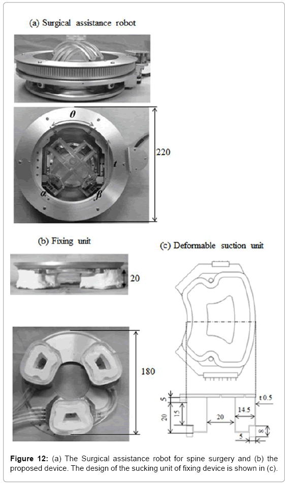
Figure 12: (a) The Surgical assistance robot for spine surgery and (b) the proposed device. The design of the sucking unit of fixing device is shown in (c).
Experiment condition
The body-mounted surgical robot is required to achieve noninvasive puncture surgery. In particular, it is beneficial for the patient whose density of bone is low. Usually, the density of cortical bone is around 0.9~1.0 g/cm3 if the patient is good health and young. The density of cancellous bone is about 0.2 g/cm3. As a patient get older, the density of cortical bone decrease and become around 0.8 g/cm3. The density of cancellous bone also decreases to 0.1 g/cm3. As is well known, the Young’s modulus of bone and the yield stress has relationship with the density of bone. Keyak et al. [12] showed that these relationship as Table 3 and Table 4. When the density of bone is low, the Young’s modulus and the yield stress is also low and the bone become breakable. To evaluate the safeness of metal pin fixation for a surgical robot, we designed a simple bilayer structure bone model and analyzed the loading behavior by using finite element method (FEM).
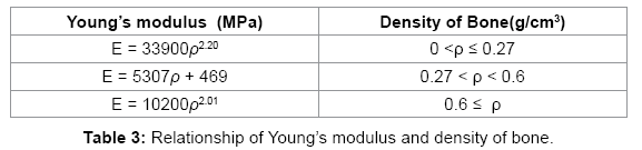
Table 3: Relationship of Young’s modulus and density of bone.
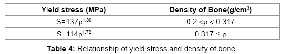
Table 4: Relationship of yield stress and density of bone.
We readied 40 mm square cancellous bone model and 2 mm thickness cortical bone model. 3 mm diameter metal pin is inserted in this model as Figure 13(a). As regards cortical bone, we readied two types of shape. One has no crack and another has small crack (Figure 13 (b) and (c)).
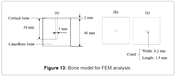
Figure 13: Bone model for FEM analysis.
A surgical robot is fixed onto a patient’s bone by more than 2 pins. So, we set three bone models and inserted pins to each model. These pins are connected by a beam as Figure 14. We calculated the von Mises stress of bone models by an external load and evaluated the safeness of metal pin fixation. The 10~40 N external loads were added to the beam and maximum von Mises stress of bone models were evaluated. The number of elements of no-crack and crack model is 93842 and 90789. The condition of constraint for the model was that only the bottom of the cancellous bone was fixed. The bottom of the cortical bone is constrained at the top of cancellous bone. The FEM analysis is calculated with the function of Inventor® (Autodesk Inc, U.S.A.).
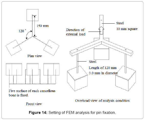
Figure 14: Setting of FEM analysis for pin fixation.
Next, we evaluated the loading behavior of a human body surface when the proposed fixing device is fixed onto the body surface. We designed a human body model by using AIST/HQL measure of human body and shape data base 2003. We extracted a part of a human back and separate it into 2 mm thickness skin, 13 mm thickness fat and muscle (Figure 15). From [13] and [14], the Young’s modulus of skin, fat and muscle are set as 0.2, 0.1, and 0.85 MPa. We connect the FEM model with the model of the proposed fixing device. The thickness of the device is 10 ~ 20 mm by location and the shape is tailored to the human body model. The Young’s modulus of this device is 0.72 MPa. We added 40 N external forces to the fixing device and evaluated the von Mises stress on the human body surface. The direction of external load is cranial, caudal end, right and left side of a patient body. The number of elements is 21947. The condition of contraint for the model was that only the bottom of the muscle part was fixed. The bottom of the fixing device is constrained at the surface of skin. The 10–40 N external loads were added to the top face of the fixing device and maximum von Mises stress of body models were evaluated. The FEM analysis is calculated with the function of Inventor®.
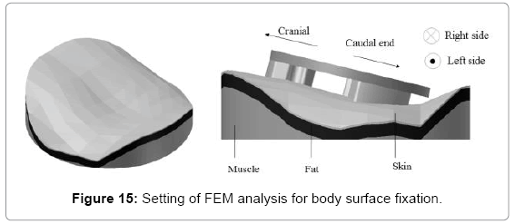
Figure 15: Setting of FEM analysis for body surface fixation.
Result
The result of FEM analysis is shown in Figure 16 and Figure 17. When a pin is inserted into the intact bone, the bone can withstands the concentration of stress, even if the density of the bone is lower than a healthy bone. However, when there is a small crack, the stress concentrates in the base of the crack and von Mises stress reaches to the yield stress of the bone. Thus, at the condition that the bone is easy to get cracked, pin fixation is not safe for the bone and there is a possibility of bone fracture.
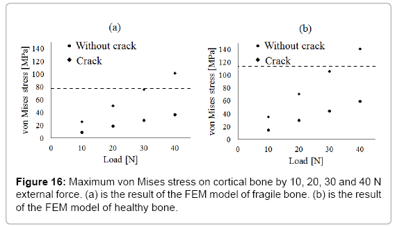
Figure 16: Maximum von Mises stress on cortical bone by 10, 20, 30 and 40 N external force. (a) is the result of the FEM model of fragile bone. (b) is the result of the FEM model of healthy bone.
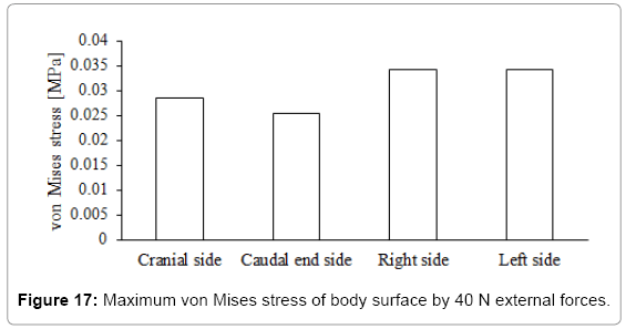
Figure 17: Maximum von Mises stress of body surface by 40 N external forces.
Maximum von Mises stress on the surface of a patient’s body is too small to injure the patient’s body surface when the proposed fixing device is fixed onto the body surface. The external force spread to the contacting area between the device and the patient. To avoid the risk of additional bone fracture, body surface fixation is adequate method.
Experiment condition
The stability of a surgical robotic system in surgery is an important factor for accurate surgical operation. We evaluated the stability and stiffness of the proposed system by measuring how well the geometrical relationship between the patient body and the proposed system is maintained during puncture operation.
To cofirm the effectiveness of the proposed fixing device for surgical assistance robot, we have to evaluate the performance of fixation on a body soft tissue and a particular shape of the affected part.
As the former target, we used the soft tissue of porcine (Figure 18 (a)). This target is abdominal tissue and consist of skin, fat and muscle. This target is punctured and fixed on a plate by a wire. In the experiment, we set the proposed fixing device and connect the proposed robot system with the target.
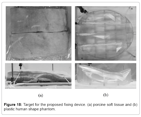
Figure 18: Target for the proposed fixing device. (a) porcine soft tissue and (b) plastic human shape phantom.
For the experiment, the load to penetrate a soft tissue is important to understand exactly the strength of the insertion force. The experimental setting condition is shown in Figure 19. We made cuts in the porcine tissue (Figure 20) and the distance from the surface of the skin to the incision are 10, 20 and 30 mm. In the experiment, we inserted the bone chip into the cut. The 3-mm-diameter needle is inserted through an incision on the skin and we measured the required puncture strength before the needle tip reach the buried bone. The maximum load in the direction of insertion that is expected during surgery is around 20 to 25 N [15,16]. Thus, after the needle hit the bone, we continue to drive the needle by the force of 25 N. The strength of loading force is controlled by monitoring 6-axis force sensor (IFS-67M25A50-I40, NITTA Co., Ltd). At the condition, we measured the maximum displacement of the fixing device from the target. The insertion direction of the needle is changed with respect to each trial. The number of trials are 6 times for each distance.
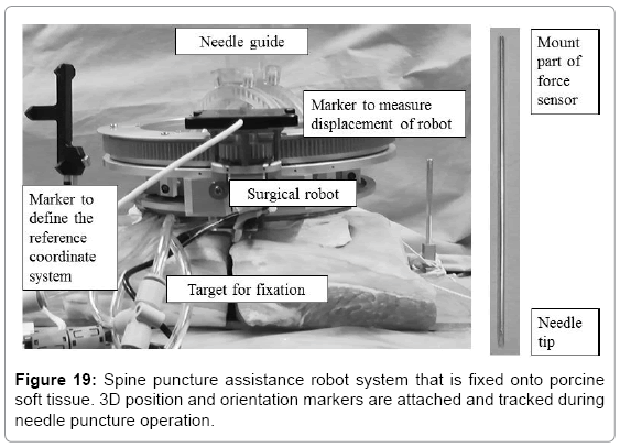
Figure 19: Spine puncture assistance robot system that is fixed onto porcine soft tissue. 3D position and orientation markers are attached and tracked during needle puncture operation.
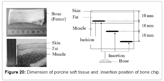
Figure 20: Dimension of porcine soft tissue and .insertion position of bone chip.
The latter target is a human shape phantom that is fabricated from acrylic resin (Fullcure720, Stratasys Ltd.) by 3D Printer (Objet EDEN260V, Stratasys Ltd.) (Figure 18(b)). The dimension data of this phantom is the dimension and shape model produced by Kawauchi; the homology average dimension and shape model. The experimental setting condition is shown in Figure21. We attached three-dimensional (3D) position markers (OPTOTRAK, NDI, Canada) to measure the displacement of the fixing device and the puncture tool during needle inserting operation. The diameter of puncture tool is 8 mm to eliminate the effect of needle deflection during this evaluation. The position displacement is calculated by the position of the needle tip before or after of applying 25 N puncture load. The insertion direction of the needle is evenly divided up 25 angles in working range, 2 times each direction.
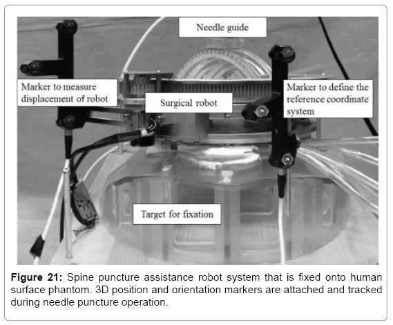
Figure 21: Spine puncture assistance robot system that is fixed onto human surface phantom. 3D position and orientation markers are attached and tracked during needle puncture operation.
Result
The insertion force that is required to penetrate soft tissue is shown in Figure 22. We evaluated the average load and the standard error of the mean. When the distance from the surface of the skin and the bone chip is 10 mm, the average insertion load was 5.0 N and the standard error of the mean (SEM) was 0.7 N. When the distance were 20 and 30 mm, the insertion loads were 7.5 ± 0.7 and 7.5 ± 1.6 N. The result of t-test is shown in Table 5. It shows that the required force to penetrate 10 mm thickness soft tissue was significantly smaller than that to penetrate 20 mm thickness soft tissue. However, we could not find the significant difference between 10 mm and 30 mm. When the distance from the surface of the skin and the bone chip is 30 mm, the amount of the distribution is bigger than that of others. The insertion force that is required to penetrate soft tissue does not depend strongly on the length of insertion pathway. So, the insertion force between 5 and 8 N is expected to penetrate soft tissue.
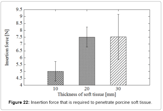
Figure 22: Insertion force that is required to penetrate porcine soft tissue.
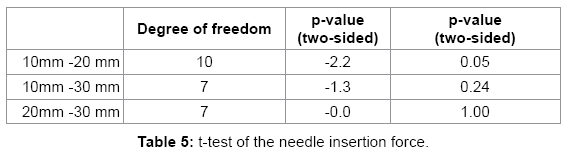
Table 5: t-test of the needle insertion force.
The displacement of the fixing device from the target is shown in Figure 23 and the result of t-test is shown in Table 6. Because the p-value of 10 mm- 30 mm test and 20 mm - 30 mm test are smaller than 0.1, we can find significant angular difference. Thus, when the thickness of the soft tissue becomes thick, the stability of the proposed fixing device decreases. When the distance from the surface of the skin and the bone is 30 mm, the average displacement were 0.87 mm and 0.37° and 1.13 mm and 0.38°in RMS.
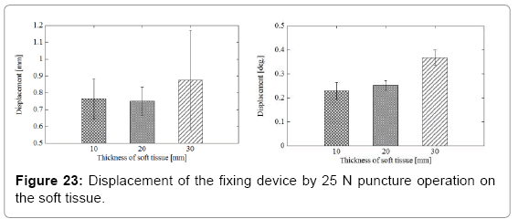
Figure 23: Displacement of the fixing device by 25 N puncture operation on the soft tissue.
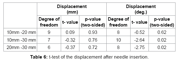
Table 6: t-test of the displacement after needle insertion.
The result of the experiment on the human shape phantom is shown in Tables 7 and 8. The displacement of the fixing device was 0.12±0.05 mm and 0.06±0.03° in average, and 0.13 mm and 0.06° in RMS. The maximum displacement of fixing device was 0.24 mm and 0.12°. The total displacement at the needle tip was 0.68±0.26 mm and 0.55±0.22° in average, and 0.73 mm and 0.59° in RMS. The maximum displacement of the needle guide was 1.16 mm and 1.18°.
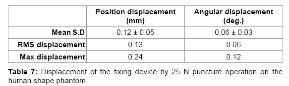
Table 7: Displacement of the fixing device by 25 N puncture operation on the human shape phantom.
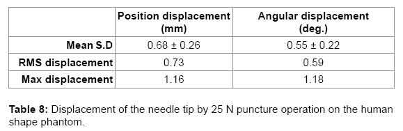
Table 8: osteoporosis-physical-puncture-operation-3-137-t008
In this research, to fix a surgical robot onto a patient’s body surface noninvasively, we designed the small surgical robot that is composed of the needle guiding mechanism and the fixing mechanism they are optimized for noninvasively puncture surgery.
First, we evaluated the dimension of the proposed fixing device. To fix the surgical robot onto a patient’s body stably, the thickness of the fixing device is important. We designed the tripod fixing device that can contour the patient’s body surface. However, if the surgical robot is smaller, the required thickness of the fixing device becomes smaller. Therefore, to increase the stability and accuracy of the robotic surgery, further downsizing of surgical robot is also challenging issue.
Next, we tested the difference between the bone fixation with inserting metal pins and the body surface fixation by using the FEM analysis. When there is a crack on the bone surface, the concentration of stress involves the local yield deformation. When the body surface fixation is introduced, the stress on the skin is small and doesn’t injure the patient’s body. Thus, for the patient who has problem with bone: such as osteoporosis or rheumatism, a pin fixation is unsafe and bodysurface fixation has specific benefit.
When this fixing device is fixed on a porcine soft tissue and needle insertion is operated, the insertion force and displacement of fixing device was measured. The required force to insert a needle into soft tissue is about 5 ~ 8 N. Thus, the load on the robot and fixing device is smaller than 25 N until the tip of needle sticks in a bone surface. When we put 25 N force on the inserted needle, the displacement were 13 mm and 0.38° in RMS on the condition that the distance from the skin surface and the bone is 30 mm. The result shows that the displacement is small for practical use (3 mm and 3°) and the proposed device partially works on biological body. Therefore, to permit more precise analysis of the function of the proposed device, the experiment in humans remains as the challenges. When this fixing device is set on a human shape phantom and 25 N needle inserting force is added, the deformation of fixing device was 0.13 mm and 0.06° in RMS. The proposed fixing method can maintain the relationship between the coordinate system of the fixing device and the human-shaped surface with acceptable level. Error of needle insertion was 0.73 mm and 0.59° in RMS when 25 N needle inserting force is loaded. The difference between the displacement of fixing device and the displacement of needle tip depends on the constitution and stiffness of the surgical robot.
Further works will be done in order to improve accuracy and stability of the surgical robot.