Advances in Automobile Engineering
Open Access
ISSN: 2167-7670
ISSN: 2167-7670
Research Article - (2016) Volume 5, Issue 2
Electric vehicles are gaining popularity due to their low carbon footprint and ease of integration with renewable energy. They are an important element in the smart grid ecosystem. Increasing the driving range of storage driven electric vehicles is the biggest challenge facing the light weight electric vehicle industry. A literature review has been performed to identify various techniques to improve the driving range. Various methods of driving range improvement such as new storage topologies, switching techniques, motor configurations are studied. A new quantitative measure called as impact factor has been derived to see the effect of each technique on the driving range. Impact factor for different methods has been calculated. It is shown that increasing the storage capacity has the highest impact factor on the driving range.
<Keywords: Electric vehicles; Hybrid Electric Vehicles (HEVs); Plug in Electric Vehicle (PEV); Battery range; Ultracap; Vehicle chargers; Regenerative braking; Vehicle to grid (V2G)
Electric vehicles have been around since early 19th century [1,2]. However, the electricity was primarily generated using coal and other fossil fuels. Driving electric vehicles meant double energy conversion, first one was from fossil fuel to electric energy and the second one was from electric energy to kinetic energy. This made it economically expensive solution. In addition to that, ample oil reserves were discovered and gasoline powered vehicles became the most cost and energy efficient means of transport. Now that the world is facing severe shortages in the gasoline and rising effects of environmental pollution such as climate changes, efforts are being carried out to reduce the pollution and improve the carbon footprint. Every country has set out policies and framework for achieving this target. This has given a significant boost to the research and development in the areas of renewable energy sources and electric vehicles. There is a strong connection between the two. As the renewable energy sources have become cheaper and commercially attractive, more energy is being generated by them. These sources are intermittent and hence they need storage for their complete utilization. With ever-evolving storage technologies, the electric vehicles became economically a more viable option. Besides giving power to the electric vehicles, storage made them an important element in the smart grid.
There are many different terminologies for the electric vehicles based on their utilization of electricity. Grid connected electric vehicles are the ones which use the electricity from overhead or underground cables. Typically, electric trains and trolley buses are developed using this concept. Battery based electric vehicles have rechargeable batteries on the vehicles. The vehicle uses the energy from the battery. Battery needs to be charged after the drive. The Hybrid Electric Vehicles (HEV) use a battery and conventional fuels to run the vehicles. The battery in the hybrid electric vehicles does not need separate charging as it gets charged from the vehicle stoppings, also known as regenerative braking. The Plug-in Electric Vehicles (PEV) use batteries which can be charged from regular electricity power outlet in a house or any commercial place. The plug-in hybrid electric vehicle uses a similar concept for a hybrid electric vehicle. Since large-scale grid-connected electric vehicles like trains and trolley buses require a lot of infrastructures, most of the electric vehicles research focus is shifted towards either entire storage based electric vehicles or hybrid electric vehicles which have the ability to run on electricity and conventional fuels [3,4].
Depending on the type of the electric vehicle, various technology areas are being worked upon. One of the technology areas in the electric vehicles is the development of newer control architectures. Researchers are working on many different electrical topologies and control strategies to improve the overall performance of the electric vehicles. These topologies are primarily for driving the electric motor [5,6]. Development of battery charging circuits is another research area. Various battery chargers such as on board, off board and wireless chargers are being developed [7-9]. Grid stability and electrical load management issues are also studied extensively in connection with the electric vehicles [10,11]. Using the battery in electric vehicles, excess grid energy from the renewables can be stored and also the same battery can be used by the grid operator to help the grid recover from short-term voltage sags and dips caused by load changes. Despite this academic level research on various aspects, the entire growth in the storage device driven electric vehicle industry in the commercial segment is focused on a single problem. This problem is to extend its driving distance with longer charge durations.
The purpose of this paper is to present a literature review of the various methods researchers have developed to improve the driving range. To improve the driving range of the vehicle, it is necessary to understand its basic building blocks and its connection to the driving range. Hence, section 2 discusses the basic structure of the electric vehicle. Section 3 presents various methods to improve the driving range. A comparison of methods and their impact on the driving range is performed in section 4 and section 5 concludes the paper.
All the electric vehicles have four main building blocks. They are as follows: A. Battery to generate a DC voltage, B. A DC to AC converter to convert the DC voltage to a high-frequency AC voltage, C. An AC motor coupled to the drive train and D. The battery charger circuit to charge the batteries. Sometimes, an additional DC to DC converter is also required to step up the low voltage from the batteries. Figure 1 shows a block diagram of the electric vehicle. The details of each building block are discussed next.

Figure 1: Block diagram of an electric vehicle.
Patient demography is shown in Table 1. The Clinical Report Form (CRF) included follow-up investigation with patient history, echocardiography, blood samples and QoL assessment 1, 3 and 6 months after surgery. Exercise testing was also done after 6 months.
| Battery size (WHr) | 30000 |
| Miles Per Gallon Equivalent | 126 |
| Energy required by the drive (WHr) | 267.5 |
| Efficiency of the motor | 0.95 |
| Efficiency of the mechanical drive train | 0.9 |
| Efficiency of the electronics | 0.98 |
| Operating window of the battery | 0.9 |
| Effective Battery energy (WHr) | 22623.3 |
| Driving range (Miles) | 84.6 |
Table 1: Calculation for the driving range.
Battery
The battery specifications for the electric vehicles differ for different types of electric vehicles. Most of the cars use lithium-ion batteries with 370V as nominal DC voltage. The battery capacity ranges from 20 kWh to 100 kWh. Higher is the battery capacity, more is the driving range of the vehicle. The driving range for the current electric vehicles ranges from 60 miles per charge to 380 miles per charge.
DC to AC converter
DC to AC converts the DC voltage to an AC voltage with varying frequency and voltage. This enables smooth speed control of the vehicle. The input DC voltage to this converter has a nominal operating range of 280V to 360V. This voltage is generated either by directly using high voltage batteries or a separate step-up converter along with the low voltage batteries.
Motor
Three types of motors are used for electric vehicles. They are brushless permanent magnet synchronous motors, AC induction motors and switched reluctance motors. AC induction motors are more popular for cars for various reasons [12]. They have ease of manufacturing and lower cost. They also have good overall efficiency over the entire load and speed operating range. They also need less maintenance due to lack of brushes. The permanent magnet motors have high starting torque and have high peak efficiency. They are used in medium weight or traction applications. Switched reluctance motors are the recent additions to the electric vehicle. They do not need permanent magnets on the rotor and have high efficiency and high torque.
Battery chargers
Most of the electric vehicles are supplied with onboard chargers. They are categorized into level 1 or level 2 chargers [13]. They can take input from the AC voltage of the residential electricity outlet and convert the AC voltage into a DC voltage to charge the battery. They are slow chargers but are most popular due to direct AC outlet connections. Level 1 chargers take input from 110V AC and level 2 chargers take input from 220V AC. To have fast charging abilities, level 3 and level 4 chargers were developed. They are high voltage DC charges which bypass the onboard chargers completely. Level 3 chargers have the ability to provide up to 50 kW of power per vehicle and level 4 chargers have the ability to provide 120 kW of power per vehicle.
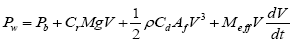
The power required by any electric vehicle at the wheel consists of four main components [14-16]. First is the base electric load such as a heater, air conditioning, music system etc. Second is the power required to overcome aerodynamic drag or air resistance to the vehicle? The third component is the power required to overcome rolling resistance by the wheels. The fourth component is the power required to work against gravity during upwards and downwards slope of the road and fifth is power required for overcoming inertia of the vehicle. The total power at the wheels Pw is given by equation 1.
 (1)
(1)
 (2)
(2)
Where, Pb is the base electric load measured in watt, Cr is the dimensionless co-efficient of rolling resistance, M is the mass of the vehicle, g is the acceleration due to gravity in m/s2, v is the velocity of the vehicle in m/s, ρ is the density of the air in Kg/m3, Cd is the dimensionless co-efficient of the drag, and Af is the frontal area of the vehicle [14,15]. Further we get,
 (3)
(3)
Where, ‘Mr’ is the vehicle inertia and ‘M’ is the mass of the vehicle expressed in Kg. Due to the moment of inertia, the effective mass of the vehicle is increased by about 10% [14].
For measuring the driving range, two types of driving cycle, namely city and highway driving cycles are considered. City driving cycle has many stops or brakes. Braking regenerates a lot of the lost energy from the vehicle. In the highway driving cycle the vehicle drives continuously at some average speed. Regardless of the type of driving, Average energy Ew over one driving cycle is given by integrating the individual components of required driving power over the cycle as shown in equation 4.
 (4)
(4)
Where t, is the total driving time. The driving range R is given by equation:
 (5)
(5)
Where Eb is the energy in the battery and D is the driving distance in m.
 (6)
(6)
Where n is the efficiency of the entire traction system, ΔSOC is the window of battery state of charge and Eint is the initial battery energy. n is further given by equation:
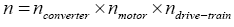 (7)
(7)
Driving range of any electric vehicle can be improved by improving any of its building blocks. Following sections discuss various methods researchers have been used to improve the driving range.
Improved storage technology
Storage technology has been evolving rapidly. Lithium-ion batteries are the most popular choice for electric vehicles due to their high capacity and light weight [17,18]. Many materials are being used for the cathode, anode, and electrolytes for increasing the efficiency and overall battery performance [19]. Some of the common materials for the cathode are Lithium Manganese Oxide (LMO) or Lithium Iron Phosphate (LFP). Lithium iron phosphate has the high current capability with very good thermal performance and less aging. They also easily replace lead acid by stacking in multiples of 4 cells. Lithium Nickel Cobalt Manganese oxide batteries have high energy density and good thermal characteristics. They are the most popular batteries for electric bikes. Besides researching on using different ions of Lithium, completely different materials are being used for packing very high energy density. One such alternative is Lithium sulfur battery. It has theoretically, 3 to 4 times the energy density than the conventional lithium ion battery. The lithium-air battery is another promising alternative where the battery capacity is increased by 5 to 10 times with very light weight [20,21].
Driving range can also be increased by adding different storage materials on top of batteries. This system of combining multiple types storage devices is known as Hybrid Energy Storage System (HESS) [22,23]. One option in this system is using ultracapacitors or supercapacitors in parallel with batteries. Ultra-capacitors can store the energy for a short time but have an infinite number of charge and discharge cycles theoretically. The power electronics converters can be designed to take input from ultracapacitors during fast high energy bursts and keep the batteries for steady state operation. Figure 2 shows various ways in which ultracapacitor can be connected in parallel with the battery. Figure 2a shows a direct parallel connection of the battery with the ultracapacitor. Figure 2b shows a bi-directional DC to DC converter balancing the power flow between battery and ultracapacitor. Figure 2c shows two separate inputs from the ultracapacitor and battery to the DC to DC converter. Figure 2d shows ultracapacitor bypassing the DC to DC converter to have high efficiency of power processing.

Figure 2: Hybrid energy storage using ultracapacitors (a) Ultracapacitors connected in parallel with the battery (b) DC to DC converters sharing power between battery and ultracapacitor (c) dual input DC to DC converter (d) Ultracapacitor bypassing the DC to DC converter.
Figure 3 shows another novel approach of combining ultracapacitors and battery. This concept is based on a bi-directional DC to DC converter with the ultracapacitor connected in series with the output of the converter. The bi-directional DC to DC converter shares the power between ultracapacitor and battery. Very high efficiency, optimum battery capacity usage and complete control over ultracapacitor current are achieved by operating the converter in different modes in different operating conditions of the vehicle. Figures 3b, 3c, 3d show all the operating modes [22].

Figure 3: A high-efficiency hybrid energy storage using ultracapacitors (a) Basic topology (b) power flow from the battery to the motor during acceleration (c) power flow during the constant speed (d) power flow during deceleration.
Fuel cells are another storage option increasingly being considered for electric vehicles [24,25]. Fuel cells have high energy density, many times higher than lithium ion batteries but they have a poor response time. Ultracapacitors have a fast response time but very low energy density. Batteries can provide high continuous power. Combining the benefits of all the three storage technologies, overall vehicle efficiency can be significantly improved. Figure 4 shows a block diagram of the system with all the three storage technologies. In this block diagram, although three separate DC to DC converters is shown to process the power from three storage mediums, configurations similar to those shown in Figures 2 and 3 can be derived for higher efficiency.

Figure 4: Hybrid energy storage using fuel cells, ultracapacitors, and battery.
Improving the converter technology
As discussed in the earlier sections, three types of motors namely brushless DC motor, AC induction motor and switched reluctance motor are considered for electric vehicles. Researchers have been working on developing different converter topologies for each type of motor. Figure 5 shows two commonly used power converter topologies [5,26].

Figure 5: Power converter topologies used in the electric vehicles.
To improve the driving range, the power converter driving the motor needs to be very efficient. Any converter loss consists of following two main components: 1. Switching loss and 2. Conduction loss. The switching loss is given by the equation below:
 (8)
(8)
Where Ton and Toff are switched on and off times in the converter.
The conduction loss is given by the equation below:
 (9)
(9)
To reduce these losses various techniques are being worked upon. One of the techniques used in is to design optimized gate driver circuit. In this method, authors have designed a new gate driver circuit which improves the turn on and turns off speeds of the power devices. This results in a reduction in switching times for the MOSFETs and hence lower switching losses. The overall efficiency of the converter is improved. Another technique for the loss reduction is using either of the two strategies known as Maximum torque for a given current (MTPC)and Maximum Efficiency (ME) for a given current [27]. The losses in the converter and the motor depend on the current and speed and also the maximum flux. These losses vary with different operating points. During low speed of operation, the losses are primarily current dependent and hence the first scheme could be used to decide the operating point. During medium to high speeds, the losses are dependent on the maximal flux in the motor. In this case, a loss model based on the flux is developed and the required current value is determined by an optimization program. The control shifts the operating point from minimum current to minimum losses.
Another approach to further minimize the losses in the MTPC strategy is to use finite predictive current control. In this method, the back EMF (Electro Motive Force) and current are estimated from the previously stored value and hence dynamic torque of the motor is improved [6].
The efficiency of the drive circuit can also be increased by introducing different modulation techniques for the switching devices. Figure 6a shows the conventional pulse width modulation technique. It is most commonly used to control the motor operation. In this modulation, at lower speed very narrow pulses are generated [28] and higher speed wide pulses are generated. This increases the AC voltage. This type of switching may not lead to optimum efficiency of the power processing. To overcome that, another technique being in use is Pulse Amplitude Modulation (PAM). In this technique, the amplitude of the pulses is varied as against the pulse width. This modulation leads to higher efficiency in some operating modes. This modulation is shown in Figure 6b.

Figure 6: (a) Pulse Width Modulation (PWM) switching (b) Pulse Amplitude Modulation (PAM) switching.
Although PAM seems to be the right approach, conventional PWM is more efficient than PAM during some parts of the operating area of the vehicle. Hence it is necessary to optimize the switch modulations over the entire operating region of the vehicle. This optimization is achieved using a chopper in front of the conventional converter circuit. The chopper varies the DC link voltage and the converter modulates the pulse widths. So, the result is quasi-PAM technique. This approach is shown in Figure 7. In this modulation, the switch is modulated using amplitude and also pulse width [28].

Figure 7: Quasi-PAM switching (a) low input voltage (b) high input voltage.
Switching frequency can also be modulated to improve the converter and motor performance. Bang-Bang type of current control has been implemented in [26] to achieve this type of modulation. Figure 8 shows this type of control.

Figure 8: Switching frequency modulation using bang-bang control.
Improvement in the motor
The electric motor is at the heart of the electric vehicle. Selecting the right motor for the drive train is very important for the overall efficiency of the drive. In applications where very high initial torque is required, brushless DC motors are used. For example, in traction or electric buses, brushless DC motors are used. They give very good peak efficiency. They use permanent magnets for their operation. The placement of permanent magnets in the motor has a good impact on its efficiency. In the study of Zhang et al. [29], three different types of magnet arrangements on the rotor are evaluated for better performance. The arrangement is shown in Figure 9a seems to perform better than the other arrangements. The effect of slot opening is also important on the motor performance. Lesser is the slot opening, better is the motor performance.

Figure 9: (a) V-type magnet arrangement in the motor (b) Alternate winding pattern for improving the efficiency.
The motor has generally two types of losses, the copper losses which occur in the windings and the iron losses which occur in the magnetic material. While the former are current driven losses, later are dependent on the switching frequency and magnetic properties of the material. The copper losses in the motor are proportional to the square of motor current as given by equation 10.
 (10)
(10)
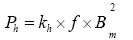
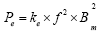
Where Pcu is the copper loss, I is the stator current and R is the winding resistance. Due to the pulse width modulating currents, the motor current has many harmonics besides the fundamental component. The effective winding resistance is different for each harmonic frequency. Many different types of PWM techniques are used to reduce the AC resistance. It is possible to control the copper losses by running the motor in loss optimization mode discussed in the previous section. The iron losses are hard to control. They include eddy current losses and the hysteresis losses and are given by equation 11and 12 [28].
 (11)
(11)
 (12)
(12)
Where Ph is the hysteresis loss, Pe is the eddy current loss, kh and ke are the loss coefficients, f is the frequency of the magnetic field, Bm is the maximum flux density and β is the Steinmetz constant. Since Bm is proportional to the voltage applied to the winding, both, hysteresis and iron losses are proportional to the voltage square and voltage to the power of β. To reduce the iron losses in the motor, one of the options is to control the voltage at the winding terminals using techniques similar to quasi-Pulse Amplitude Modulation technique discussed in. This approach gives significant efficiency improvement.
Other causes of iron losses are the high-frequency harmonics of the switching currents. Multiple windings are used during different operating modes of the motor to overcome these losses in PWM carrier harmonic iron loss reduction technique of permanent-magnet motors for electric vehicles [30]. These windings can be excited dynamically by using winding changeover circuits or using multiple converter circuits. Figure 9b shows two stator windings wound alternately on each slot for this purpose.
Use of photovoltaic sources
Photovoltaic (PV) panels can be used in multiple ways to aid the overall operation of the electric vehicles. One of the ways is to use PV panels to charge the batteries along with a DC to DC converter. The charger may or may not be part of the vehicle. In the grid-connected PV systems, the battery charger can be conventional AC to DC charger and PV can generate most of the electricity required by the vehicle. When PV is unable to charge the battery, it gets power from the grid. The second type of PV integration ison board electric charging. In this case, PV panels are installed on the body or chassis of the electric vehicle and they are used for battery charging. But, this charging can be a continuous process so that the battery does not discharge completely when the PV is present. Although the panels may be of smaller capacity, they aid in battery charging and effective driving range can be increased.
In Solar PV-powered SRM Drive for EVS with flexible energy control functions [31], a unique three-port converter is proposed which seamlessly integrate PV, battery and the motor used for driving the vehicle. The converter system has two relays. Four operating modes are formed based on opening and closing of these relays. The energy exchange takes place in all three ports without additional circuits. This saves in overall converter losses and hence the efficiency of the system is higher. Figure 10 shows this circuit.

Figure 10: Three port converter for seamless power transfer between PV, battery, and motor.
In Solar PV-powered SRM Drive for EVS with flexible energy control functions [32], an onboard, PV based battery charger is used for auto-rickshaws. Auto-rickshaws are three-wheeled, motorized vehicles to carry passengers in medium size cities of many of the developing countries. The onboard PV battery charger trickle charges the batteries and keeps them charged for a longer time. This helps in increasing the driving range significantly. Figure 11 shows a block diagram of this system.

Figure 11: A block diagram of PV based electric auto-rickshaw.
While integrating PV, the study has also been done to see the effectiveness of different panel technologies for improving the driving range. It was found in that mono and polycrystalline silicon PV panels are very effective for use with the lightweight vehicles.
Using wind power to increase the driving range
Similar to PV, wind energy can also be used to increase the driving range of the vehicle. A small wind turbine can be placed on the body of the vehicle. When the wind blows during vehicle motion, it can trickle charge the battery inside the vehicle leading to the higher driving range. The wind can be used for onboard charging or off-board charging. There has been some research and patents on this approach. For example, in the US patent 8,098,040, B1 driving range has been increased using RAM air turbines. The energy resulting from the vehicle movement is tapped by these turbines. The turbines are coupled with a generator. When the vehicle moves, the generators charge the battery. These RAM turbines are mounted inside the vehicle. The energy received by this method can also be used in conjunction with an ultra-capacitor for quick charge and discharge cycles [33]. Figure 12 shows this method.

Figure 12: Air turbine used to charge the vehicle battery.
Contactless power transfer
Traditionally battery in the electric vehicle is charged by using high voltage or low voltage grid connection. Recently there have been attempts [15,16,34] to charge the battery using inductive charging mechanism. In this mechanism, the power transfer from the source to the vehicle takes place using a magnetic coupling. This is very much like a transformer with the primary winding placed with the energy source and the secondary winding inside the vehicle. The coupling of the fields from primary to secondary winding takes place through the air (Figure 13). Although the efficiency of such conversion is low due to poor coupling through the air, it has some distinct advantages. Those are, less maintenance due to no physical contact and safety due to no risk of shocks and sparks [15,16]. Another big advantage of this type of system is, vehicle battery can be charged at ease at various locations and its effective driving range can be increased. Figure 14 shows the required infrastructure for contactless power transfer system. It has a line transformer to isolate the power line, a diode rectifier, a high frequency switching DC to AC converter which transfers AC power to the high-frequency rectifier through the air. A dc to dc converter is connected after the rectifier to charge the battery.

Figure 13: A block diagram for the contactless power transfer.

Figure 14: Impact factors of various mechanisms on the driving range improvement.
If this infrastructure is placed at the traffic signals, parking lots and even on the roads while the vehicle is in motion, the battery can replenish its charge and the effective driving range is increased.
Effective thermal management
In the countries having a cold climate, the vehicles need to be heated in the winter. This heating reduces the driving range of the vehicle by about 50% [35]. The motor and electronics circuits in the vehicle have certain losses. An electrical model showing all the losses in the car can be obtained along with a thermal model for the heat flow in the car. A combination of both these models can yield to an accurate placement of electronics so that, its losses can be used for vehicle heating. This type of thermal management can effectively recover the losses occurred during heating and hence the driving range of the vehicle is increased.
Another technique to gain from the electronics losses is the use of thermal generators. Thermal generators can be used to at the various heat generating locations and they can then trickle charge the battery to further increase the driving range.
Impact of driving behavior
Driving style has a lot of impact on driving range of the vehicle. An interesting study performed in thermal vehicle-concept study using co-simulation for optimizing driving range [36] concluded that about driving range can be improved by about 30% just by following the correct driving practices. Some of the good driving practices are as follows:
1. Reducing the difference in acceleration and deceleration.
2. Avoiding high accelerations.
3. Reducing aggression in the driving.
To reduce this impact of human behavior, seamless integration of technologies like Internet of Things (IoT) in the vehicle are necessary. With the sensors guiding the vehicle operation, the chances of errors are much less and effectively efficiency of the vehicle can be improved.
From the information written in the previous sections, all the driving range improvement techniques can be categorized into three categories. They are 1) Improvement in the storage technology, 2) Improvement in the electronics and 3) Improvement in the drive train. To find out the impact of each of these techniques, an example of the commercially available electric car is considered. This car uses a battery size of 30 kWh and goes for 126 Miles per Gallon equivalent (MPGe). The efficiencies of the motor, mechanical drive train and electronics vary based on the operating conditions. Motor efficiency ranges between 80% to 97% with 80% at the extreme end of the torquespeed curve [37]. The inverter efficiencies range from 90 to 98% and the mechanical drive train efficiency ranges between 70% to 95%. Although this is a large efficiency variation, for the driving range estimation in the low torque and medium speed range the efficiencies of the motor, electronics, and mechanical drive train can be assumed to be 95%, 98% and 90% [37]. The battery window of operation is assumed to be 90%. Table 1 shows the calculation for the driving range using equations 5, 6 and 7.
To quantify the effect of improvement, an impact factor is derived. Impact factor for this discussion is defined as the multiplication of the per unit percentage driving range improvement and the maximum possible percentage improvement in the various technology area given by equation 13.
 (13)
(13)
From equations 5, 6 and 7, it appears that one percent improvement in the motor or electronics efficiency gives 1% increase in the driving range. Similarly, a one percent increase in the storage capacity gives 1% additional driving range. However, as per the data given in Table 1, the motor and electronics efficiencies are already above 95%. Further efficiency improvement could be a very difficult task. Even if, one gets 100% efficient inverter and electronics, it means only a 5% improvement in the driving range. However, the case is different for the storage devices. Storage capacity can not only be increased by adding more storage without any theoritical limit but also, it can be increased by charge replenishment methods using PV contactless power transfer. If the storage capacity can be improved even by 10%, it has a significant impact on the driving range. Figure 14 shows the impact factors using the motor, electronics, and the storage devices. For the Figure 13, the storage maximum limit is considered as double the original value shown in Table 1. This is expected as storage devices are evolving continuously. With the availability of more advanced devices, the maximum storage limit can easily exceed to 3 to 4 times of this number with the advanced storage technologies mentioned in earlier sections.
Use of electric vehicles has been growing. Increasing the driving range of the electric vehicles is a topic of much interest in the commercial world. A detailed review of available methods to improve the driving range is presented in this paper. Driving range can be increased by using advanced storage materials, improving the converter technology, improving the motor, using renewables in the vehicles, on-road contactless power transfer, effective vehicle thermal management and following efficient driving practices. Some of the promising technologies for the storage are lithium-air batteries and hybrid storage solutions using ultracapacitors and fuel cells. Converter and motor efficiency can be increased by using advanced modulation techniques like pulse amplitude modulation and different winding patterns. An impact factor is derived from studying the effect of each different technique of the driving range improvement. The improvement in the storage has the highest impact on the effective driving range. Finally, although, the impact factor of good driving practices is hard to calculate, it does affect the driving range. Hence, seamless sensor integration and Internet of Things (IoT) into the vehicle would improve the driving range further.