Advances in Automobile Engineering
Open Access
ISSN: 2167-7670
ISSN: 2167-7670
Research Article - (2016) Volume 5, Issue 1
Battery electric vehicle is a promising candidate for future passenger vehicles due to its potential to reduce air pollution, high energy usage effficiency, and has regenerative braking. However, due to the limited range and price, potential vehicle onwers are reluctant to consider owning an EV. Moreover, the limited range of BEV has caused range anxiety among the driver. Other than improving the technology of BEV to increase the driving range, range estimator can be useful in reducing the range anxiety of BEV drivers. The conventional range estimator is used like a fuel gauge; to give a general guideline on when to recharge the vehicle and is not absolute. To further increase the confidence in BEV driving, trip based range estimation can be used in parallel with the conventional method to reduce the range anxiety.
<Keywords: Range estimation, Battery electric vehicle, Range anxiet, Dynamic range estimation system
Battery electric vehicle (BEV) is a type of vehicle which runs purely on battery power. BEVs use only electric motors as their propulsion system whereas; hybrid electric vehicles (HEVs) use an electric motor and an internal combustion engine (ICE) as their propulsion system. HEVs have the advantage of power source flexibility (electricity or petrol) but the hybrid system is very complex and it is not easy to design one. For the BEVs, they have the advantage of simple design with only one type of power source on board (battery). The battery pack for BEVs has lower energy density compared to fossil fuel resulting in a shorter driving range compared to conventional vehicle of the same weight. Moreover, BEVs have lengthy charging time and limited charging infrastructure. Even with super chargers, it will still require about 20 minutes to charge the vehicle to 80% full [1]. Battery swapping is as fast as refueling a vehicle but the method is not fully implemented and there are still questions on the implementation of the system as the battery system of BEVs are not standardized and depends on the car manufacturers. These disadvantages, hinders the implementation of BEVs on a larger scale.
Despite of the challenges, BEV is one of the candidates for reducing air pollution. This is because BEV is able to charge from any electrical source such as thermal power plants and renewable energy sources. It is mentioned that, BEV can significantly reduce air pollution if charged completely from renewable energy sources [2]. Besides that, BEVs have advantages such as high level of energy efficiency, zero tailpipe emissions, low rate of noise, less moving parts thus requiring less maintenance, and regenerative braking [3].
Due to the limited driving range of BEVs, the term “range anxiety” is closely linked with the use of BEVs [4]. Range anxiety is the fear of being stranded on the road due to insufficient charge of the vehicle. Range anxiety will cause the drivers to perceive the driving range a lot less than it should be [5]. Besides finding solution to increase the driving range of the vehicle, improving the range estimation system can provide an additional help in reducing the range anxiety [5]. With range estimation system, the drivers are able to monitor the available driving range and decide accordingly (to charge the vehicle or not). However, the current range estimation system is not reliable and accurate enough. The range estimation is only valid under certain conditions [5]. This is because, besides the vehicle dynamic factors, a BEV’s range is also affected by the electrical and electronic components such as the air-conditioning, lighting and entertainment system. All of these energies are provided by the battery pack of the BEV. For a conventional vehicle, the electrical energy is supplied by the auxiliary battery which is charged from the alternator of the vehicle. The energy from a running ICE will be wasted anyways if not in used as heat energy. Hence using the electronics component will not have significant effect on the range of the conventional vehicles but will affect the range of BEVs.
In this paper, three range estimation methods will be investigated and compared. The first method is the conventional method used in most of the BEVs in the current market. Second method is contour positioning system (CPS). Third method is dynamic range estimator (DRE).
Conventional method
There are a few BEVs currently available in the market such as Nissan Leaf, Tesla Model S, Toyota RAV4 EV, and Renault Z.E. each with their own range estimator. For Nissan Leaf, the driving range is constantly being calculated based on the amount of available battery charge and the actual power consumption average [6]. For Tesla Model S, the driving range is estimated based on the amount of available battery charge and energy consumption over the last tenth of a mile and assumed to be driving at ideal conditions with no additional energy consumption such as air conditioning [7]. For Toyota RA4 EV, the driving range is estimated based on the amount of charge remaining in the battery, air conditioning system mode and so on [8]. For Renault Z.E., the driving range is estimated based on average energy usage over the last 200 km [9]. In general, the driving range estimation in the commercial BEV uses the average power or average energy consumption and the SOC of battery to estimate the driving range. There are also alternative ways to estimate the SOC of battery [10] but it is not covered in this paper. This paper investigates the method used to estimate the power/ energy consumption of BEV needed to estimate the driving range. Equation (1) and (2) describe the basic method of estimating driving range based on the vehicles mentioned previously.
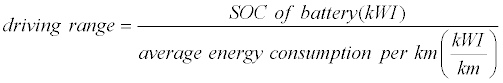 (1)
(1)
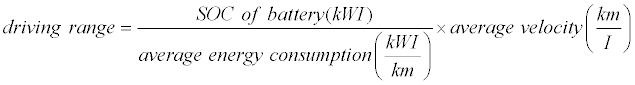 (2)
(2)
The average power and energy consumption data is obtained based on the historical data of the vehicle which does not necessary reflect the actual driving behaviour. Like the fuel gauge of a conventional vehicle, these range estimators are used as a general guideline to know when to recharge the BEV.
Contour positioning system (CPS)
Contour Positioning System (CPS) is a novel range estimation technique for electric vehicles [11]. Instead of using historical data for the range estimation, the CPS predicts the future power consumption of the BEV. This is done based on (3) [12].
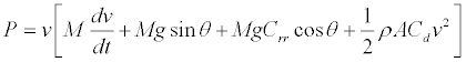 (3)
(3)
P is the power consumed by the vehicle, v is the speed of the vehicle, M is the mass of the vehicle, g is the acceleration due to gravity, θ is the gradient of the road in degree, Crr is the coefficient of rolling resistance, ρ is the air density, A is the frontal area of the vehicle, and Cd is the drag coefficient. Equation (3) includes the power consumed for accelerating, rolling resistance of the wheel, driving up and down slopes, and aerodynamic drag. CPS works by extracting road contour distance and elevation heights data from Google Earth’s elevation profile and using them to produce the road contour slope angles [13]. The data obtained is used with (3) to provide an estimation of the amount of battery needed for the user‘s selected route. For CPS, the vehicle is assumed to be driving at constant speed (acceleration = 0) hence, the power consumed by the vehicle is estimated based on a fixed constant speed. The energy consumed from the trip can be easily calculated from the power required, distance of the trip, and the driving speed of the vehicle.
CPS is better in estimating the energy consumption than the conventional method. However, without the acceleration term in (3), CPS will only predict the minimum power required for the trip. The acceleration of the vehicle is affected by the driving behaviour that affects the overall energy consumption of the BEV. Besides that, the CPS does not include auxiliary loads in their energy estimation.
Dynamic range estimator (DRE)
DRE is a model-based range estimator for BEVs. The proposed method basically uses the driver’s response to stimulus to form a fixed driving behaviour. The driving behaviour is used to virtually ‘drive’ and maintain the BEV to a user defined target speed while responding to road loads of the route. Compared to CPS, the DRE includes driving behaviour, power train efficiency, and auxiliary loads in estimating the energy consumption of the vehicle. Equation (4) describes the force required to move the vehicle [14,15].
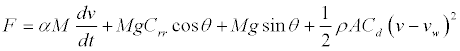 (4)
(4)
Where F is the traction force, α is a constant to include the inertia of rotating components as it is not always easy to obtain the values directly [14]. M is the net mass of the vehicle, v is the vehicle speed, g is the acceleration due to gravity, Crr is the rolling resistance coefficient, θ is the slope on the road, ρ is the air density, A is frontal area of the car, Cd is the drag coefficient, and vw is the wind velocity. The first term on the right of (4), represents the linear acceleration of the vehicle. The constant α is taken to be 1.05. The second term represents the rolling resistance and the third term represents the incline resistance while the last term is the aerodynamic drag where, v – vw is the relative velocity between the wind speed and the vehicle speed [15]. The tractive force, F is provided by an electric motor. Permanent magnet brushed dc motor is used for this study because permanent magnet brushless dc motor (PM BLDC) is commonly used in electric vehicles and has a torque to current equation similar to that of the PMDC motor under dq-axes [16]. However, PMDC has a simple control and it is much easier to understand and model it. The traction force produced by the gear train is given by (5), where, η is the efficiency of gear train, G is the gear ratio and r is the radius of the wheels. The electromagnetic torque, Tm produced by the electric motor is proportional to current I as in (6), where kt, is the torque constant of the motor. The transfer function of the electric motor is given by (7), where V, is the input voltage (controlled by the driver), Eb is the back emf, L is the inductance of the motor and R is the electrical resistance of the motor. The back emf of the motor can be obtained from (8), where kb is the back emf constant and ω is the rotational speed of the motor shaft in rad/s.
 (5)
(5)
 (6)
(6)
 (7)
(7)
 (8)
(8)
After rearranging (5) – (8), the dynamic equation of the vehicle is formed as shown in (9). Equation (9) relates the acceleration of the vehicle with the vehicle dynamics and propulsion system.
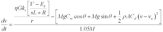 (9)
(9)
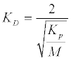
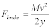
Driving behaviour is a complex model. The driver’s driving pattern will change according to their mood or physical condition [17]. DRE uses a fixed aggressive driving mode to estimate the energy consumption since driving aggressively consumes the most energy. Aggressive driving refers to rapid acceleration and braking, and speeding [18]. The throttle and the brake each are modeled using traditional PID controllers while the decision to switch between the throttle is done through Matlab Simulink stateflow tool box. Figure 1 shows the block diagram for the vehicle speed control. The throttle and the motor controller are controlled using a PI controller. Figure 2 shows the block diagram of the PD controller for the brake control. A rate limiter block is added into the PD controller to ensure a more human like behaviour in term of response. The value for KP and the derivative constant, KD are calculated based on (10). The maximum magnitude of the brake force is calculated based on (11) [19] where,Fbrake represents the vehicle braking force and y is the stopping distance. The typical stopping distance (not counting reaction time) for 112 km/h or 31.11 m/s is 75 m [20].

Figure 1: Block diagram for the vehicle speed control.

Figure 2: Block diagram for brake control – PD controller.
 (10)
(10)
 (11)
(11)
Figure 3 shows the decision flow chart for the driver. The error in Figure 3 represents the speed difference between the desired speed and the vehicle’s actual speed. ‘Foot on Throttle’ and ‘Foot on Brake’ are the outcomes of the decision, whether to control the throttle or the brake. Th is the threshold for overshoot from the desired speed by Th and the throttle value is zero, then the driver will apply the brake. ‘t1’ and ‘t2’ represent the time taken for the driver to switch between the throttle and the brake. The delay times are included so to make the driving model as realistic as possible.

Figure 3: Driving decision flowchart (to switch between the throttle and brakes).
After estimating the energy consumed for a trip, the energy consumed by the auxiliary load is added up to know the net energy consumption. The power consumption for the auxiliary load is about 6 kW [21].
Only the result for CPS and DRE will be compared. This is because both CPS and DRE are predicting the future power/energy consumption for a specific trip whereas the conventional method is used to determine the remaining driving range of the vehicle regardless of trips. If no journey is specified, the conventional method should still be used.
The parameter used for the vehicle model in DRE is the same with CPS in order to be able to compare with each other. However, DRE has more parameter values than CPS as it includes the propulsion system (electric motor, single transmission). Three cases are used to compare the difference between CPS and DRE.
5 km downhill (no auxiliary load)
Figure 4 shows the elevation profile for 5 km downhill. Overall, the slope is going downwards as seen in Figure 4. The target speed for both CPS and DRE is 90 km/h. Figure 5 shows the power consumption profile for CPS and Figure 6 shows the power consumption profile for DRE. Table 1 summarize the energy consumption of CPS and DRE.
| Method | Energy Used, kWh | Energy Used (15.9kWh = 100%) | Percentage of Difference, % |
|---|---|---|---|
| CPS | 0.455965 | 2.87 | 3.68 |
| DRE | 0.439186 | 2.76 |
Table 1: Energy consumption for 5 km downhill.

Figure 4: Elevation profile for 5 km downhill.

Figure 5: Power consumption profile for 5 km downhill (CPS).
Based on Figures 5 and 6, more power is consumed during the start of the trip for Figure 6. Furthermore, Figure 6 has higher peak power than Figure 5. However, from Table 1, the overall energy consumed in DRE is lower compared to CPS, 3.68% lesser than CPS. This is because for DRE, the power consuming period is slightly shorter.

Figure 6: Power consumption profile for 5 km downhill (DRE).
5 km three-hills (no auxiliary load)
Figure 7 shows the elevation profile for 5 km three-hills. Figure 8 shows the power consumption profile for CPS and Figure 9 shows the power consumption profile for DRE. Table 2 summarizes the energy consumption of CPS and DRE.

Figure 7: Elevation profile for 5 km three-hills.

Figure 8: Power consumption profile for 5 km three-hills (CPS).

Figure 9: Power consumption profile for 5 km three-hills (DRE).
| Method | Energy Used, kWh | Energy Used (15.9kWh = 100%) | Percentage of Difference, % |
|---|---|---|---|
| CPS | 1.229858 | 7.73 | 21.29 |
| DRE | 1.491649 | 9.38 |
Table 2: Energy consumption comparison for 5 km three-hills.<
For driving up hilly roads, DRE consumes more energy compared to CPS as seen in Table 2. Based on Figures 8 and 9, DRE consumes more power compared that of CPS. The highest power consumption is during the start of the vehicle. This is because the vehicle has to accelerate to pick up speed to reach the target speed of 90 km/h.
5 km highway (no auxiliary load)
Figure 10 shows the elevation profile for 5 km downhill. The route taken is from certain part of the north-south highway. Figure 11 shows the power consumption profile for CPS and Figure 12 shows the power consumption profile for DRE. Table 3 summarizes the energy consumption of CPS and DRE.
| Method | Energy Used, kWh | Energy Used (15.9kWh = 100%) | Percentage of Difference, % |
|---|---|---|---|
| CPS | 0.518422 | 3.26 | 28.79 |
| DRE | 0.667677 | 4.20 |
Table 3: Energy consumption comparison for 5 km highway.

Figure 10: Elevation profile for 5 km highway.
Overall, the power consumption for DRE is higher than CPS as seen in Figures 11 and 12. It is during the initial of the trip where the power consumption is the highest. It can be seen that, the power consumption is higher when the slope is going up while lower when the slope is going down.

Figure 11: Power consumption profile for 5 km highway (CPS).

Figure 12: Power consumption profile for 5 km highway (DRE).
UTAR to technology park Malaysia (no auxiliary load)
Figure 13 shows the elevation profile between UTAR (Setapak Campus) to Technology Park Malaysia (TPM). Only result from DRE will be presented in this section. Figure 14 shows the cumulative energy consumption for different reference speeds. Based on Figure 14, it can be seen that each energy profiles look like scaled version of the other profiles. Without considering auxiliary loads, the highest speed consumes the most energy but requires the least amount of time to reach the destination as seen in Figure 14 and Table 4. However, the energy consumption slightly increases when the speed goes too low. Generally speaking, the trip elapse increases with decreasing speed but not necessary for the energy consumption.
| Speed, km/h | Time Taken | Energy Used, kWh |
|---|---|---|
| 10 | 1h 31min 17s | 1.279929 |
| 20 | 45min 45s | 1.216814 |
| 40 | 22min 55s | 1.262026 |
| 60 | 15min 19s | 1.394126 |
| 80 | 11min 31s | 1.594234 |
| 90 | 10min 16s | 1.722944 |
| 100 | 9min 15s | 1.870170 |
| 120 | 7min 45s | 2.216322 |
Table 4: Data comparison for different driving speed.

Figure 13: Elevation profile between UTAR and Technology Park Malaysia.

Figure 14: Cumulative energy consumption for different reference speeds (UTAR toTechnology Park Malaysia).
UTAR to technology park Malaysia (with auxiliary load)
With the same elevation profile as in Figures 13 and 15 shows the cumulative energy consumption for different reference speeds but with auxiliary loads included. Table 5 summarizes the data of Figure 15.

Figure 15: Cumulative energy consumed for different reference speeds and with auxiliary loads (UTAR to Technology Park Malaysia).
Based on Figure 15 and Table 5, it can be seen that, the lowest driving speed will consume the most energy. This is because the energy consumed by the auxiliary load is time dependent. The longer the duration of use, the more energy is consumed given that the same power is consumed. From Table 5, the optimum speed to drive to conserved energy and save time is between 60 to 90 km/h.
| Speed, km/h | Energy Used, kWh | Time Taken | Percentage of Difference, % | |
|---|---|---|---|---|
| Auxilary Load OFF | Auxilary Load ON | |||
| 10 | 1.279929 | 10.408473 | 1h 31min 17s | 713.21 |
| 20 | 1.216814 | 5.7892703 | 45min 45s | 375.77 |
| 40 | 1.262026 | 3.5529437 | 22min 55s | 181.53 |
| 60 | 1.394126 | 2.9245926 | 15min 19s | 109.78 |
| 80 | 1.594234 | 2.7460207 | 11min 31s | 72.25 |
| 90 | 1.722944 | 2.7477754 | 10min 16s | 59.48 |
| 100 | 1.870170 | 2.7944906 | 9min 15s | 49.42 |
| 120 | 2.216322 | 2.9906972 | 7min 45s | 34.94 |
Table 5: Data comparison for different driving speed with and without auxiliary load.
Conventional range estimator for battery electric vehicle is based on historical data and is used as a basic notification for the driver on when to charge. A route based range estimator would provide a better insight of the energy consumption of the vehicle. The drivers are able to plan ahead for a trip using a route based range estimator as the estimator such as CPS and DRE predicts the future power/ energy consumption. Turning on auxiliary loads on a BEV will have significant impact on the driving range. Due to the auxiliary loads, driving too slowly will consume even more energy than driving at higher speeds. To conserve energy, the driver should drive the BEV at the optimum speed.