Journal of Aeronautics & Aerospace Engineering
Open Access
ISSN: 2168-9792
ISSN: 2168-9792
Research - (2020)Volume 9, Issue 2
This paper represents the study of effect of wing sweep on blended wing body aircraft at different sweep angles with fixed platform design. A3-D BWB model was designed in CATIA V5 and simulation was carried in ANSYS fluent. Twenty-three BWB geometries with varying sweep ranging from -400 (forward sweep angle) to 550 (backward sweep angle) were designed, with the aero foil profiles and twist distribution unchanged from the original geometry. This gives insight on the platform of the design. The simulations were carried out using Euler solutions of flow field. The body was meshed with unstructured grids with tetrahedral and triangular shapes. The best sweep angle BWB was found between forward and backward sweep angles. The best sweep angle was considered and the angle of attack of the whole body of the aircraft was changed. The stalling angle of attack of the aircraft was found using the best sweep angle.
Blended wing body; Wing sweep; Lift to Drag ratio (L/D); Coefficient of lift (Cl); Coefficient of drag (Cd); Lift (L); Drag (D),Coefficient of lift/Coefficient of Drag (Cl/Cd)
Ever since the first aircraft designed and flown by Wright Brothers in 1903, many improvements were done to achieve better design and performances. But much of the advancements were made in the aerodynamics, propulsion systems, structures, materials and electronics and apart from the minor changes, the blueprint of the airplane geometry i.e., the classic tube and wing design has always been constant. With the increasing concern for the environment and the depleting fuels, research has been going on to develop a more efficient and environmentally friendly aircrafts, hence unconventional designs are gaining popularity in the recent decades. Blended Wing Body configuration has an unconventional design in which the wing and fuselage are blended to form an aircraft. Researches have shown that this design concept offers a significant improvement in the aerodynamic efficiency compared to the conventional aircraft yet the concept has to develop for the commercial transport aircrafts (Figure 1).

Figure 1: The BWB concept.
The BWB concept has been inspired from the flying wing aircraft; it combined the aerodynamic advantages of flying wing with the loading capabilities of that of traditional aircraft, by increasing the volume of the wing at the center to act as a fuselage. This allows BWB aircraft to carry more passengers and cargos. Some conceptual Unmanned Air Vehicle (UAV) designed based on the blended delta wing-body configurations exhibit vortex-dominated flows.
Research has reported some aerodynamic, stability and control issues for these configurations. A three-dimensional surface aerodynamic optimization for a given BWB plan form was reported in reference using an adjoint method with trim constraint. This article reports a further study of the BWB geometry for various wing sweep angles, as wing sweep is one of the most important plan form design parameters for transonic aircraft As the wing is swept backwards, the velocity component normal to the leading edge becomes smaller than the aircraft’s actual speed, thereby reducing the compressibility effects, the wave drag, and also the aircraft’s generated lift (which can be met by increasing the cruise speed or by using different aero foils) [1].
The present work focuses on the aerodynamic study of the blended wing body configuration at transonic speeds. The model was designed in CATIA V5 and then the analysis was done in ANSYS fluent. In the first analysis the best sweep angle was determined and with the best sweep angle the stalling angle of the aircraft was determined.
For the analysis the design was carried out in various ways. Mentioned below are the points of the whole design process.
Selecting the airfoils
The BWB can be divided into-the body and the wing. The majority of the lift was to be produced by the center body and the wing would have the control surfaces to maneuver the airplane. A total of ten cambered and symmetry airfoils were selected the list was shortened to only four airfoils: LA 2573A, HS 522, MH78 and NACA 25111. Out of which NACA 25112 and MH78 was used to design the BWB model. The NACA 25112 was used to generate high lift a high lift generating airfoil was required which has high lift coefficient of about 0.82 and also the L/D ratio of the airfoil was high compared to other airfoils. The MH78 airfoil can give negative moment of coefficient (CM) thus the outer wing must have a positive CM in order to balance out its effects. CM contributes to the longitudinal stability. Since the BWB is a tailless aircraft they can counter the negative pitching moment. The airfoils coordinates were selected from airfoiltool.com and the variation of Cl, Cd, Cm and the graph of the variation was analyzed in the airfoiltools.com [2].
Centre of gravity, twist and dihedral angle
The center of gravity (CG) is the point at which the aircraft would balance were it possible to suspend it at that point. As the location of the center of gravity affects the stability of the aircraft, it must fall within specified limits that are established by the aircraft manufacturer.
Twist is applied to wings so that the outboard section of the wing does not stall first. When an aircraft is pitching nose up and increasing its angle of attack, the airflow over the wing eventually reaches a point where it becomes turbulent, causing a loss in lift. The dihedral of a wing determines the amount of self-correction capability an aircraft has in the roll axis (Figure 2 and Table 1).

Figure 2: Graphical representation of (a) Cl/Cd vs. Alpha, (b) Cl vs. Alpha, (c) Cm vs. Alpha.
Table 1: Variation in aerodynamic characteristics of the airfoils.
| Airfoils | Cl | Average Cm | Max Cl/Cd |
|---|---|---|---|
| LA 2573A | 0.62 | 0.02 | 123 |
| HS 522 | 1.3 | -0.01 | 100 |
| MH78 | 1.4 | 0.04 | 105 |
| NACA 25112 | 1.55 | -0.01 | 122 |
Performance parameters
Wing loading, stall speed and the maximum lift coefficient are essential to determine whether the plane will fly or not. The main portion of the lift is generated from the center body. Therefore, if stall condition is applied only to the center body then the minimum wing loading can be found. It can be seen from Table 1 that the maximum CL is approximately 1.55 for NACA 25111. The following lift equation can be used to calculate the wing loading.
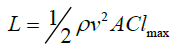 (1)
(1)
Where the left side denotes the wing loading, ρ is the density; v is the stall speed and is the maximum CL. The expected weight of the plane including the battery, motors, electronics and the payload etc. Thus working with the equation will give us a minimum area [3-7].
Winglets
Blended winglets are the aircraft industry’s latest winglet innovation. Blended airplane winglets are sleek, highly effective wingtip devices which, unlike traditional upward facing winglets, are smoothly integrated into the wing. Because the sweep of the area where the winglet meets the wing itself creates less drag than traditional winglets, blended winglets provide even more fuel efficiency.
Creating GSD points
The following steps were followed:
• The coordinate points of the airfoils were copied into the excel sheet where X,Y and Z coordinates were present.
• The macros were applied to the points which helped in importing the coordinate points to the CATIA software for designing the model.
• The aircraft was modeled with 7 airfoils out of which 4 were used for the center body and the rest 3 were used by the wing.
Modeling (CATIA V5)
The following steps were involved in the process of modeling of CATIA:
• These coordinates were imported to GSD points plotter were the aero foil coordinates can be imported to CATIA V5.
• All the aero foil coordinates were plotted and the surface or volume sweep was given to the aero foil.
• Winglets were made with the help of the plane creation at a particular height.
• Out of the entire sweep angles 43 degree backward sweep was the best.
• Considering this entire only 43 degree backward sweep model was used to find the stalling angle of attack of aircraft (Figure 3 and Table 2).

Figure 3: (a) BWB 43 degree sweep angle, (b) Top view of sections, (c) Isometric view of final design.
Table 2: Final plane configuration.
| Section # | From center chord/in | Offset (from center)/ in | Chord/ in | Air-foil name | Thickness % |
|---|---|---|---|---|---|
| 1 | 0 | 0 | 31 | NACA 25111 | 11 |
| 2 | 2 | 3.5 | 27.5 | NACA 25111 | 11 |
| 3 | 4 | 7.5 | 23.5 | NACA 25111 | 10.6 |
| 4 | 6 | 9.5 | 21.5 | NACA 25111 | 8.2 |
| 5 | 9 | 12.6 | 14.5 | MH 78 | 6.9 |
| 6 | 12.3 | 15.8 | 9.5 | MH 78 | 5.2 |
| 7 | 24 | 28 | 3 | MH 78 | 4 |
| Aspect ratio 4.6 | CG 16.2 in from Y | Area: 546.8 in2 | |||
Geometric modeling
• In CFD process ANSYS fluent was used
• The CATIA model was then imported to the ANSYS software for analysis
• A rectangular grid domains of size 4 times the chord to the intake and 6 times the chord to the outlet and 6 times the chord to the upper and lower surface are generated around model to produce a unstructured grid in the computational domain.
• The BWB models Angel of attack was changed from 1 degree to 45 degree to find the best stalling angle (Figure 4).

Figure 4: (a-h) Represents side view of geometric model of BWB of: 43 Degree Sweep Angle 1 deg AOA, -43 degree sweep angle 10 deg AOA, -43 degree sweep angle 15 deg AOA, -43 degree sweep angle 20 deg AOA, 43 degree sweep angle 30 deg AOA, -43 degree sweep angle 35 deg AOA, -43 degree sweep angle 4 deg AOA, -43 degree sweep angle 45 deg AOA respectively.
Meshing
• Mesh is generated around the full model using the commercial meshing software ANSYS with the solver fluent.
• The grid used for the simulation is tetrahedral unstructured grid everywhere except the tip of the wing where triangular type is generated.
• The adjacent plane to the model act as symmetry plane. The mesh contains 3-6 lakhs cells and was generated and nodes were up to 48000-120000.
• Face meshing was done with a relevance of 100 and relevance center-medium.
• The far field was in fluid state condition.
• The figures below show the meshed model and differences in Angle of attack of the aircraft (Figure 5).

Figure 5: (a, c-l) Represents side view of meshed model of BWB of: 43 degree sweep angle 1 deg AOA, 43 degree sweep angle 5 deg AOA, 43 degree sweep angle 15 deg AOA, 43 degree sweep angle 20 deg AOA, 43 degree sweep angle 25 deg AOA, 43 degree sweep angle 30 deg AOA, 43 degree sweep angle 35 deg AOA, 43 degree sweep angle 40 deg AOA, 43 degree sweep angle 45 deg AOA, 30 degree sweep angle, 40 degree sweep angle respectively; (b, m) Represents of 3D view of meshed model of BWB of: 43 degree sweep angle 1 deg AOA and 40 degree sweep angle respectively.
Grid adaptation
Grid adaptation is a method by which cells are refined in areas of large gradients of properties, which help in pressure, velocity and density counters.
If the cells aspect ratio is more the truncation error is more. By grid adaptation, these truncation errors can be reduced to provide a more accurate and reliable solution due to a more even distribution of errors.
The meshed model shown below is the model with 3-6 lakh nodes and lakh elements.
The meshed model shown below has element–4400000 and nodes -1200000 and it had a skewness of 0.79 and aspect ratio of 6.7 which was best for getting accurate results. It was not able to be solved as it would take 3 to 4 days for solving 1 model and the computers couldn’t handle the heat. So, the elements and nodes with less number were used. As the Software was cracked version and student version some of the operations were not valid and some restrictions were found for better meshing.
Shocks could have been found if the model had structured grid and a better version of the software.
Set-up and solver
• Solve is used to solve the meshed model of the BWB.
• The model to use density based solver as the speed was transonic (0.8 Mach)
• The turbulent model was SST K-omega for the transonic speed and if the speed is subsonic then k-epsilon could be used.
• The Boundary conditions are given below
• Boundary inlet where; Type: Pressure Farfield, Location: D_Inlet, Flow regime: Transonic, Mach no: 0.8, Total temperature: 3.00e+02 [K].
• Boundary outlet where; Type: Pressure outlet, Location: D_ Outlet, Flow regime: Transonic, Gauge: Pressure 0 Pascal
• Boundary of wall where; Type: Wall, Mass and momentum: No slip Stationary wall, Wall roughness smooth wall:
Standard condition
• Boundary of aircraft where; Type: Wall, Mass and momentum: No slip stationary wall, Wall roughness: Smooth wall Standard condition
• The best sweep angle at 43 degree has an L/D ratio 15.23 which was best obtained from 22 different models.
• This best sweep angle was considered and the stalling Angle of attack was determined
• The pressure counters shown below are the variation in Angle of attack from 1 degree to 45 degree
• We can see that the pressure on the upper surface of the aircraft goes to a maximum of about 3.29×E005 for 35 degree where the aircraft stalls at a Cl max of 0.369.
• From lift equation we can say that velocity Sq increases coefficient of lift decreases.
• Since velocity is inversely proportional to coefficient of lift (Figure 6 and Table 3).

Figure 6: (a-j) Represents pressure counter of: 1 deg AOA, 5 deg AOA, 10 deg AOA, 15 deg AOA, 20 deg AOA, 25 deg AOA, 30 deg AOA, 35 deg AOA, 40 deg AOA, 45 deg AOA respectively.
Table 3: Obtained and calculated forces for BWB aircraft.
| Alpha | Lift(N) | Darg(N) | Cl | Cd |
|---|---|---|---|---|
| 0 | 859.87 | 113.87 | 0.02498 | 0.002165 |
| 1 | 1554.15 | 131.17 | 0.0336 | 0.00284 |
| 2 | 2943.48 | 162.74 | 0.06381 | 0.003528 |
| 3 | 3948.85 | 200.38 | 0.08561 | 0.00434 |
| 4 | 4457.51 | 216.49 | 0.09663 | 0.004693 |
| 5 | 5309.69 | 303.23 | 0.1151 | 0.00657 |
| 6 | 6491.56 | 376.59 | 0.14 | 0.0081 |
| 7 | 7428.7 | 483.1 | 0.161 | 0.001047 |
| 8 | 8602.55 | 600.82 | 0.1865 | 0.01302 |
| 9 | 8980.95 | 690.45 | 0.19578 | 0.0156 |
| 10 | 9953.5 | 862.84 | 0.21587 | 0.0187 |
| 15 | 12355.9 | 2312.6 | 0.26787 | 0.05013 |
| 20 | 13974.4 | 3811.5 | 0.30296 | 0.08263 |
| 25 | 14309.6 | 5207.3 | 0.311023 | 0.112895 |
| 30 | 14894.6 | 7211.3 | 0.33291 | 0.15634 |
| 35 | 17053.7 | 9080.6 | 0.3697 | 0.19686 |
| 40 | 14768.4 | 10729 | 0.32017 | 0.2326 |
| 45 | 14070.6 | 12344.9 | 0.305 | 0.2676 |
The lift coefficient CL equation is given by:
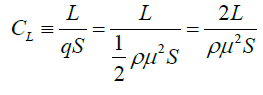 (2)
(2)
For stalling angle of attack
Aerodynamic characteristics of BWB
The below graphs shows the variation of lift and drag vs. Angle of attack
• Max lift was obtained at 35 degree AOA of 17053.721 N
• Max drag was obtained at 45 degree AOA of 12344.956 N
• Stalling angle of attack was obtained at 35 degree (cl-0.3697)
Lift vs. Angle of attack
The lift vs. Angle of attack (α), for deflection from 05 to 45 degrees. The curves have similar trends where lift coefficient increase as angle of attack increase until it reaches its maximum value at around 35°. Beyond this angle, the lift coefficient decreases as angle of attack increases [6,7].
Drag vs. Angle of attack
The variation of D (Drag) with respect to angle of attack (α). The drag increases as the angle of attack increases (Figure 7).

Figure 7: Graphical representation of Lift vs. AOA, drag vs. AOA, cl vs. AOA, L/D vs. AOA respectively.
Lift coefficient vs. Angle of attack
The Lift Coefficient vs. Angle of attack (α), the results obtained are as follows, Value of CL (Lift Coefficient) increases as the angle of attack increases until its maximum value at around α=35° and decreases with lower slope. Value of CL max increases as the air velocity of wind tunnel increases. Hence CL max increases with increase in Reynolds number.
Lift-to-drag ratio vs. Angle of attack
Lift-to-drag ratio (L/D) versus angle of attack (α), curves are presented in fig below, The curve shows a maximum value of L/D about 21 degree at α=04° and decreases as.
The aim of the project was to design a small scale BWB aircraft for different sweep angles (forward and rearward). In consideration of their lift and moment characteristics, NACA 25111 and MH78 were selected for the center body and the wing respectively. The aero foils were used to construct a model in CATIA V5 and then it was exported to ANSYS software for the analysis. The coefficient of lift, coefficient of drag and coefficient of moment of the BWB aircraft were investigated in steady state CFD at Mach no regime at transonic flow.
From the above analysis we got to know the best sweep angle is 43° and stalling angle of attack was 35 degree and the Clmax=0.3697 for the best sweep angle and we can still give twist and dihedral dimensions to this geometry so that better design will give the best performance.
• The L/D ratio of a BWB aircraft at different sweep angle is identified.
• The best sweep angle is determined.
• The stalling angle for the best sweep angle is determined.
From the above analysis we got to know the best sweep angle is 43° and stalling angle of attack was 35 degree and the Clmax=0.3697 for the best sweep angle and The BWB can still be given twist and dihedral dimensions to this geometry so that better design will give the best performance. For the future work the body of the aircraft can be modeled and tested in wind tunnel and compare the theoretical value to the practical value for further references.
Citation: Darshan N, Deepa MS, Komalesh BE (2020) Effect of Stall on blended Wing Body Aircraft. J Aeronaut Aerospace Eng. 9:223. doi: 10. 35248/2168-9792.20.9.223.
Received: 22-Jun-2020 Accepted: 29-Jul-2020 Published: 05-Aug-2020 , DOI: 10.35248/2168-9792.20.9.223
Copyright: © 2020 Darshan N, et al. This is an open access article distributed under the term of the Creative Commons Attribution License, which permits unrestricted use, distribution, and reproduction in any medium, provided the original work is properly cited.