Advances in Automobile Engineering
Open Access
ISSN: 2167-7670
ISSN: 2167-7670
Research Article - (2016) Volume 5, Issue 2
Crankshafts are one of the most important parts of a reciprocating engine. İt basically connects driveline system to the pistons which gives the motion. Main aim of Crankshaft systems designs are to have lower bearing forces, lower torsional vibrations and higher fatigue strength. But, due to complexity of the geometry, lack of manufacturing quality and nonlinear forces, it is hard to analyze the characteristics of the crankshaft. In this paper, a 2D representation of a crankshaft model was built with load information from connecting rods and other specifications. The resultant bearing forces and harmonics of the crankshafts were calculated with given data. The AVL Excite software program was used to simulate the crankshaft of an engine.Crankshafts are one of the most important parts of a reciprocating engine. İt basically connects driveline system to the pistons which gives the motion. Main aim of Crankshaft systems designs are to have lower bearing forces, lower torsional vibrations and higher fatigue strength. But, due to complexity of the geometry, lack of manufacturing quality and nonlinear forces, it is hard to analyze the characteristics of the crankshaft. In this paper, a 2D representation of a crankshaft model was built with load information from connecting rods and other specifications. The resultant bearing forces and harmonics of the crankshafts were calculated with given data. The AVL Excite software program was used to simulate the crankshaft of an engine.
<Keywords: Torsional vibration; TV damper; Crankshaft
All rotating machine assemblies experience torsional vibrations while working. As a result, rotating and reciprocating devices must be observed with respect to torsional vibration in order to avoid failures. Torsional vibration leads noise, wear and efficiency decrease.
Magnitude of torsional vibrations leads extra stresses on shafts. These stresses have relationship between operating speed and natural frequencies of shaft systems. This stress also relies on stress concentrations and damping coefficients.
Huge amount books and technical papers Wachel and Szenasi [1] are done on torsional vibration, so the phenomenon is generally thought to be well understood and controlled. However, torsional vibration problems still happen in reciprocating engines. Most of the studies are carried out with the aid of finite element method since the methodology saves cost and time and it is able to solve problems with complicated geometry shape [2].
Different ways have been tried to control torsional vibration of reciprocating engine, such as improving the balance of crankshaft, designing dynamic vibration absorber at end of crankshaft, using torsional vibration damper (TVD). The TVD is one more reliable way to control vibration.
AVL Excite software is used for modelling and simulation of the reciprocating engine and all calculations and restrictions are also done on Cukurova University Automotive Engineering Laboratory.
TV dampers are used to decrease torsional vibration effects. Damping refers to the extraction of kinetic energy from a vibrating system by means of thermal conversion [3]. It has the effect of keeping the vibration deflection within acceptable limits once the resonance point has been passed. Damping refers to the extraction of kinetic energy from a vibrating system by means of thermal conversion [4]. It has the effect of keeping the vibration deflection within acceptable limits once the resonance point has been passed (Figure 1).

Figure 1: Transmissibility graph.
The damping factor d is coupled to the damping ratio ? by:
 (1)
(1)
Where;
? = damping ratio (relation of damping energy/spring energy)
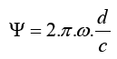
? = natural frequency of the TV damper
d = relative damping
c = torsional stiffness of the damper
The natural frequency of the damper is calculated from;
 (2)
(2)
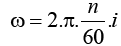 (3)
(3)
where;
n = engine speed,
i = engine order,
J [kgm2] = Mass moment of inertia of the damper ring,
In order to model and simulate the system AVL Excite software is used. It leads crank train and driveline design analysis with less set of data and performs modal analysis of the system and determines its torsional frequencies and torsional modes, as well as critical speeds [5-8]. And finally, AVL Excite can results of dynamic forced response calculation include dynamic torques, angular displacements, and dissipation power of torsional vibration damper (Figure 2).

Figure 2: Engine illustration.
The required conrod and bearing parameters are entered on Excite designer part. The crankshaft details such as geometric parameters are entered with shaft modeller branch. On shaft modeller branch TV damper values and crankshaft stiffness values and geometric details are entered as seen in Figure 3.

Figure 3: Shaft modeller.
On this paper, one parametric analyse of TV damper will be done. TV damper inertia and TV damper stiffness will be changed between 0.003-0.005 kg.m2 and 1.107-3.107 N.m/rad. The observed parameters are total maximum stress on the crankshaft part, maximum torque on the crankshaft, the maximum deformation on TV damper, maximum dissipated power.
The models were run for the applied boundary and loading conditions. Maximum dissipated power is shown in Figure 4. Higher torsional stiffness and TV damper inertias leads dissipated power to higher magnitudes [9]. It is found that maximum dissipated power of elastic rubber of TV damper dissipated 210 W too much dissipated power can lead rubber to burn.

Figure 4: Maximum total deformation graph.
Maximum total deformation of TV damper is also illustrated in Figure 5. The maximum deformation changes within the range 0.4 deg to 0.7 deg. And maximum deformation can be achieved with 2.107 torsional stiffness values. Damper ring inertia has nearly linear relationship with deformation magnitude.

Figure 5: Total deformation illustration.
The other step of the simulation was the maximum torque analysis. In this analysis, it is seen that maximum torque occurs at web8. The result shows that the total torque is higher with lower stiffness values of TV damper (Figure 6).

Figure 6: Maximum total torque graph.
Last step of simulation was maximum total stress on the crankshaft. That graph shows how torsional vibration can increase the stresses until 66 MPa and leads failures [10]. Higher torsional stiffness values can increase the safety while decreasing magnitude of stress (Figure 7).

Figure 7: Maximum total stress graph.
From the AVL Excite simulation tests, the following results were summarized;
• TV Damper inertia and stiffness values have a huge impact on mechanical properties of reciprocating engines.
• Lower stiffness values increase the torsional torque on the system.
• Decreasing the inertia of the damper can eliminate deformation and dissipated power on the TV damper
• All tests results revealed that web8 part of crankshaft is the most critical part due to higher torque values on it.
• Maximum stress on the crankshaft have relationship between TV Damper stiffness value
The authors acknowledge AVL-AST, Graz, Austria for providing us AVL-Excite Designer under the AVL-Çukurova University Partnership Program.