Journal of Pollution Effects & Control
Open Access
ISSN: 2375-4397
ISSN: 2375-4397
Research Article - (2021)Volume 9, Issue 4
Machining processes must not only be efficient in terms of technical requirements and economic problems for the current industry, but they must also be sustainable in terms of environment and operator safety. The use of cutting fluids during turning is costly and can be hazardous for the operator. However, dry machining induces excessive friction on the tool/workpiece and chip/tool interfaces, leading to an increase in the fine and ultrafine particles generation which deteriorate air quality in the workshop. This dust can constitute a real risk to the operator’s health and shorten the reliability of the machine-tools components. Knowing the cutting conditions leading to reduced metallic particle generation could contribute to improving the occupational safety of the machining processes. This article presents experimental and theoretical investigations on dust generation phenomenon during dry turning of aluminum alloys. The main object is to evaluate the dust generation as a function of machining conditions through the temperature and force cutting prediction induced by dry machining in order to determine safe and economic machining process windows. The cutting conditions effects on the temperature increasing in orthogonal cutting have been studied using various theoretical models. This increase in temperature controls the dust generation during dry machining. A theoretical model is proposed in this work to study the correlation between cutting mechanisms, plastic deformation and dust generation. The model predictions were compared with the experimental data and the accuracy of the obtained result is well investigated due to the simplification used in the proposed model. The model was capable of predicting the data with a correlation greater than 94.5% for orthogonal cutting of 7075-T6, 6061- T6 aluminum alloys. Also, a comparison was made between the proposed model and another model based on the constitutive equation of Needleman-Lemonds. Difference among the prediction from the two models was relatively small, suggesting that these models have a broad common basis.
Johnson–Cook and Oxley Model, Dry Machining, Cutting Temperature, Dust Generation, Air Quality
The machining process has improved massively because of the engineering contribution in this field with a common objective of achieving the efficiency of machining processes. Rao mentioned that chemical machining especially produces carbon dioxide and solvents that are difficult to degrade in groundwater [1]. Currently, the manufacturing process would replace chemical machining by mechanical machining which is more ecological, more accurate and predictable. Shamsudin et al. [2] noted that the mechanical machining offers better chips recycling and also avoids the hazardous substances emission in an important quantity. On the other hand, setting the process- related controllable variables to optimal operating conditions and with minimum effect of uncontrollable or noise variables on levels and dependent variability are essential in machining
Process [2]. So to achieve this objective, the selection of the optimal machining conditions is a key factor [3]. Turning is one of the simplest central machining processes. Cutting force, tool life and surface roughness are related to turning parameters. Mia et al., conclude that ideal selection of the cutting parameters can obtain a lower cutting force, maximum material removal rate, longer tool life, better surface roughness and a minimum cost [4]. Molinari and Nouari note that some categories of criteria were used for optimization instead of using the specific cost in turning operation (machining time, material removal rate, and tool life or dust generation) [5].
The material removal is an extremely complex thermo-mechanical process. Determining the temperature in the chip forming zone is essential to understanding the cutting phenomenon. Islam et al., proposed a model where the chip and the process change discontinuously, this model evaluated the transient temperature in interrupted cutting operations [6]. Also, Childs successfully predicted chip formation in steels machining by hardening behavior, the model supposes the same flow stress thermal softening and a temperature independent strain rate hardening [7]. Peng's modelling approach shows precise predictions in terms of the cutting forces and the chip formation [8]. Sima and Özel observed that the thermo-mechanical coupling in material constitutive models is carried out by the plastic deformation work, the frictional work and the thermal softening effect on flow stress magnitudes [9]. Follansbee concluded that the dependences of the temperature and the strain- rate in the simulations of strain are related to appropriate internal state variables, hence the importance of defining them well so that the capacity to model is accurate [10]. The search for a model with independent variables of the turning process which describes metal deformation is required. Merchant has well described the force relationships permit to calculate different quantities such as the work done in shearing the metal and in overcoming friction on the tool face [11]. Hastings et al., have described an approximate machining theory is in which account is taken of the temperature and strain-rate dependent properties of the work material [12]. Xie et al., analyzed the formation of shear localized chips in orthogonal machining by a simplified theory of instability of plastic flow [13]. The results of this investigation provide remedying problems associated with chip formation and temperature generated in metal cutting. The shearing strains during chip formation, the shear rate and of chip flow can be quantitatively determined in the case of orthogonal cutting. Karpat and Özel developed an analytical model to access the local stress and heat flux distribution [14]. Palmer and Oxley extended the existing theories of cutting by including the effect of work- hardening and it appeared that consistency had been found [15]. This led to a physical consistent of the cutting process, which was taking place during the tests. Lalwani et al., considered in their analysis the effect of strain, strain-rate and temperature at tool/chip interface which is ignored by many researchers [16]. They presented an extension of Oxley’s predictive analytical model. Jomaa et al., proposed an analysis based on an extension of the Oxley's machining theory, this analysis is applied in the case of high-speed machining of ductile and hard metals [17]. In this analysis, the materials' behavior was modelled using the Marusich's constitutive equation. The results of this analysis showed a reasonable agreement for all tested materials between the predicted and experimental cutting forces. A constitutive model was elaborated by Johnson–Cook which gives a close approach to the material behaviour, taking in consideration strain and strain-rate hardening, as well as thermal softening of the material [18]. Jaspers and Dautzenberg prove the model limitation for some materials. The coupling effect of strain and strain-rate isn’t considered so the thermal effect doesn’t appear in the proposed model [19]. Dou et al., simulated the orthogonal cutting based on hydrodynamic and Johnson–Cook models [20]. The results showed that the prediction by the Johnson–Cook model of the maximum equivalent strain, size of secondary deformation zone and stresses in the primary deformation zone were higher than those obtained with the hydrodynamic model. Paturi et al., f proposed two constitutive models based on shear friction model and Pure deformation method (modified Johnson–Cook and modified Zerilli-Armstrong models) [21]. The predicted shear plane angle and tool/chip contact temperature using modified Zerilli-Armstrong were slightly more accurate than those obtained by using modified Johnson–Cook model.
Dry machining and high speed machining are increasingly attempted because of their impact on manufacturing cost. Decreasing the use of lubricant or dry-machined can improve machining performance (better air quality and reduce the machining costs). Dry machining processes and MQL such as turning are accompanied by aerosols generation (fogs, fine chips and metallic dust in both micrometers and nanometers scales) that has impacts on operators’ health [22]. Diseases caused by exposure to dust range from simple respiratory irritation to bronchitis, asthma and cancer. Sustainable manufacturing regulations require manufacturing to reduce manufacturing hazards, especially for micro-particles and ultrafine particles. Indoor air quality has become an important matter for health and safety issues in machine shops because of the risks associated with exposure to metallic particles. Nevertheless, for today industry, machining processes should not only be effective in terms of technical requirements and economic issues, but also they should be sustainable in terms of environments and operator’s safety. Khettabi et al., concluded that the flow rate should be also optimized in order to enhance the machining performance and reduce the particles generation during the metal working process [23]. The formation of fine and ultrafine particles during machining is attributable to different phenomena, such as: macroscopic and microscopic friction, plastic deformation and chip formation mode according to Songmene et al., [24]. The most effective way of reducing dust exposure is to reduce the dust generation at the source. The dust generation mechanism is not caused purely by the mechanical effect, as the temperature of the chip formation zone also plays a big role in this mechanism. The temperature involved in the cutting process alters the mechanical properties of the material, and modifies the chip formation mode and the dust generation. Djebara et al., studied the effect of artificial aging on machinability using an innovative criterion (dust generation) [25]. The results indicate that under the same cutting conditions, one of the artificial aging generates less dust emissions level compared to the others (32% less than). Ugulino and Hernández have developed regression models for estimating dust generation for each particle size fraction as a function of average chip thickness and cutting depth [26]. Independent cutting parameters can influence the chip thickness and resulting dust generation and surface quality during machining. Khettabi et al., developed a hybrid model of particle generation during machining processes which was based on the energy approach, combined with macroscopic friction (tool-chip), micro-friction, and plastic deformation of materials [27]. Based on the difficulty and inaccuracy of the experimental measurements, a predictive modelling is imposed in our case. Based on the difficulty and inaccuracy of the experimental measurements, a predictive modelling is imposed in our case. Some assumptions should be considered in order to resolve the multi-physical problem as temperature, strain rates, and material behaviour is all related to each other. In this work, a study was carried out in order to underline the effect of cutting forces and cutting temperatures on the dust generation. The dust generation evaluation by a combined constitutive model (J-C & Oxley) has been developed and studied. A comparison between the proposed model and the hybrid model of Khettabi et al., will be discussed [27]. Finally, the comparison between the prediction model and the corresponding experimental results will also be established.
Experimental Procedures
Orthogonal cutting tests were conducted on a MAZAK NEXUS vertical CNC machine (3-axis) using ceramic inserts with uncoated tungsten carbide for the 6061-T6 and 7075-T6 aluminium alloys with dry cutting. Cutting tool was mounted on tool holder with a rake angle of -5°. It is to underline that similar inserts were used during the tests in order to ensure the reliability of the inserts properties used. A number of techniques have been developed to measure cutting temperatures. In the present work, the cutting temperature in the cutting tool was measured by means of a chromel-alumel thermocouple (type K) with a diameter of 0.075 mm. The thermocouple response time is 0.03 s. The uncertainty on the temperature measurement resulting from this type of thermocouple is 0.4% for the maximum value. This technique is relatively easy to apply; we measure the average temperature over the entire tool/chip interface. The workpiece was disc- shaped, with an external diameter of 70 mm and a thickness of 4 mm. The chemical compositions, physical properties, Johnson-Cook parameters and model constants for the orthogonal cutting of 6061-T6 and 7075-T6 aluminum alloy are defined in Table 1:
| Chemical compositions | Si | Mg | P | Cu | Mn | Zn | Cr | Ti | Fe Al |
| A6061-T6 | 0.7 | 1.0 | 0.2 | 0.28 | 0.1 | 0.22 | 0.2 | 0.12 | 0.2 Balance |
| A7075-T6 | 0.08 | 2.7 | 0.17 | 1.40 | 0.03 | 6.1 | 0.19 | 0.2 | 0.17 |
| Physical properties | ρw (Kg/m3) | Kw (W/m°C) | Cw (J/Kg°C) | Tm (°C) | ρt (Kg/m3) | Kt (W/m°C) | Ct (J/Kg°C) | ||
| A6061-T6 | 2700 | 167 | 896 | 585 | 11900 | 86 | 337 | ||
| A7075-T6 | 2850 | 130 | 960 | 620 | 11900 | 86 | 337 | ||
| Dust Model Constants | Ra (m) | C | max | A | Ea (w/mm2) | friction coefficient () | |||
| A6061-T6 | 0.075 | 1.50 | 6.2 | 8.0 | 1.2510-4 | 160 | 0.5 | ||
| A7075-T6 | 0.075 | 1.50 | 6.2 | 8.0 | 1.2510-4 | 160 | 0.5 | ||
| J-C Constants | A | B | C | n | m | ||||
| References | |||||||||
| A6061-T6 | 324 | 114 | 0.002 | 0.42 | 1.34 | [28] | |||
| A7075-T6 | 496 | 310 | 0.017 | 0.30 | 1.20 | [29] | |||
Table 1: Chemical and physical parameters of aluminium alloys for the tested specimens.
The cutting forces were measured using a three-direction
dynamometer table (Kistler 9255-B) mounted on the machine table. Measured values processing must be calculated from the eight output signals of the charge amplifier. Forces, moments and application points of forces are calculated and output from force measurement platforms. The cutting forces were analyzed using the sampling frequency of 48 KHz after being amplified. The raw force signals were digitally filtered (FFT) and analyzed using Matlab code to process the data. The cutting forces are the average values taken over a stable period (0.3-5.5 s) depending on the combination of cutting speed and feed rate. The orthogonal machining performance was estimated based on the cutting force (Fc). Chips were prepared for metallographic examinations for each experiment. The Hitachi scanning electron microscope (SEM-3600N) was used to examine the resulting properties of the chips under different cutting conditions. To that end, the chips were ultrasonically cleaned in ethanol bath before being examined to SEM microscope. Values average of the chip thickness at three different locations far enough from the two ends is measured using a digital micrometre. Dust- Trak II (8530) and Aerodynamic Particle Sizer (TSI-3321 APS) was used to quantify the particles generation. Near the cutting area, APS and Dust-Trak were connected to a suction pipe at a flow rate of 5 l/min. The dust was collected before, during and after each cutting process until it returned to the initial ambient concentration (3 min). A data acquisition and analysis computer was connected to the measuring device. The experimental setup is shown in Figure 1.

Figure 1. Experimental setup: Mazak CNC milling machine used for orthogonal cutting.
In this research, orthogonal cutting tests were performed at different cutting speeds and feed rates. The depth of cut was kept constant for all the tests. 5 levels of speeds and 5 levels of feeds were used in the design of experiments (Table 2). The mass concentration was used as one output response, this is the dust generation which representing the total mass per unit volume. The total number of experiments performed was 12 experiments. The orthogonal cutting tests were replicated three times for each cutting condition.
| Variable parameter | -2 | -1 | 0 | +1 | +2 | Levels |
|---|---|---|---|---|---|---|
| Cutting speed (m/min) | 156 | 300 | 650 | 1000 | 1144 | 5 |
| Feed rate (mm/rev) | 0.01 | 0.08 | 0.15 | 0.25 | 0.29 | 5 |
Table 2: Orthogonal machining process parameters and conditions.
A6061-T6 & A7075-T6 Aluminium alloys
Theoretical Evaluation of Dust Generation
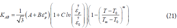
The J-C model is a relationship used in machining to theoretically define the residual stresses, the temperature and the cutting force. It is efficient, simple and easy to use. The model is a semi-empirical which predicts the stress distribution in material subjected to high strain rates, high stress and high temperatures. The following equation gives the J-C model:
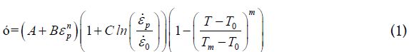
The given formula is composed of three products successively representing strain, strain rate, and temperature where σ is the equivalent flow stress, εp equivalent plastic strain, εp the equivalent plastic strain rate, εo the reference strain rate, the work material temperature, Tm the melting temperature, To the ambient temperature, and (A, B, C, n, m) are the J-C constants.
The shear angle φ used in the current study was proposed by the Merchant model as follows [10]:
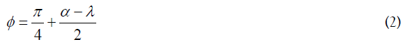
Where α is the rake angle, and λ is the mean friction angle which is equals to arctan (μ).
Ozlu et al., proposes an analytical model on the rake face, it is a dual zone contact model on the tool/chip interface [30]. Contact length Cl is obtained as follows:
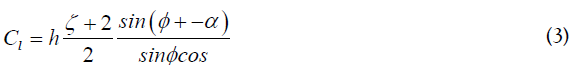
Where h is the uncut chip thickness, and ζ is the pressure distribution (≈ 3).
Chip formation model is used when α is the rake angle (geometric specification of the cutting tools). In the case of a non-continuous cut, the modified rake angle α* (geometrical-based model) is defined as follows [31]:
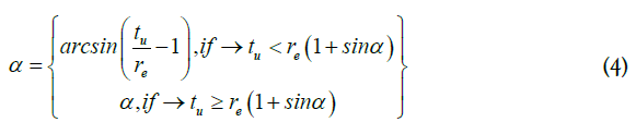
With the compression ratio given as a function of the shear angle and the modified rake angle as follows:
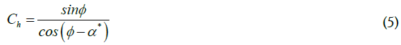
Xie et al., found that the product of the cutting speed and feed rate for which the chip segmentation begins generates several critical values [12]. Segmentation is also defined based on the segmentation band density [30]. The segmentation density ηs is the inverse of the contact length:

Hastings et al., reject geometric parameters to calculate state variables (strains, strain rates and stresses) [11]. This formulation is proposed:
The average strain rate  can be evaluated as a function of the
thickness of the shear zone
can be evaluated as a function of the
thickness of the shear zone  and the workpiece velocity V:
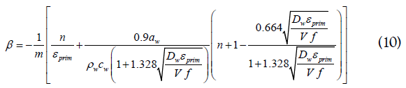
Oxley proposed a shear zone model for orthogonal machining to understand the cutting mechanism. He considered a shear zone that extended on both sides of the shear plane [32]. Thus, strain hardening of the material during chip formation can be considered. In addition, it assumed a perfectly sharp tool, plane strain, uniform normal and shear stresses at the tool/chip interface, so that the model considers only continuous chip formation, ignored the effective cutting-edge radius and the stagnation point. Huang and Aifantis proposed a model to compute the shear zone thickness to define the heat-transfer of the shearing area band [33]:
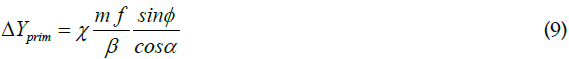
Where m is the material strain rate sensitivity coefficient and β is the flow localization parameter and f is the cutting feed.
 is the strain,
  is the thermal softening coefficient and n is
the strain hardening coefficient,
is the thermal softening coefficient and n is
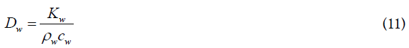
the strain hardening coefficient,  is the thermal diffusivity can
be calculated by using
is the thermal diffusivity can
be calculated by using  ,
,  , and
, and  as:
as:
Using Eq.10, we are able to plot the flow localization parameter. The βmax is identified directly from the graph and βc is the value at which the chip becomes segmented.
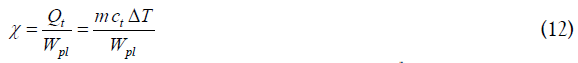
A large amount of the plastic work Wpl is converted into thermal energy Qt in a machining process due to internal friction. The Taylor-Quinney coefficient χ defines the percentage that is converted adiabatically into heat from the plastic strain energy density [34]:
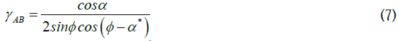
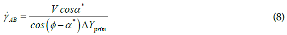
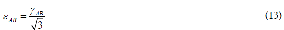
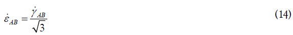
The equivalent strain εAB and the strain rate εAB are expressed as:
High strain-rate of the materials implies a significant release of heat, resulting from the thermo-mechanical coupling effect by which part of the mechanical work involved in the deformation process is evacuated from the solid as heat. The plastic work as function of the flow stress, the strain variation and the thermal variation is expressed by Børvik et al., as follows [35]:
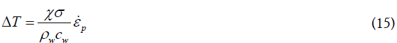
For the cold work of the material [36]:

By replacing the stress expression Eq.1 in Eq.15 we obtain:
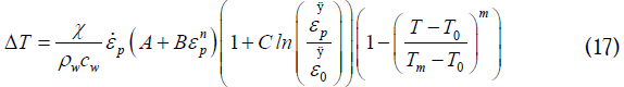
The temperature rise  can be calculated using the numerical
resolution of the Eq.17.
can be calculated using the numerical
resolution of the Eq.17.
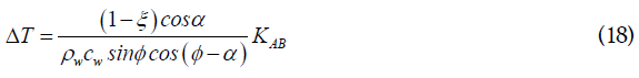
Boothroyd and Bailey established a thermo-plastic model in the
primary shear zone which depends on the plastic work absorbed
and converted into heat [37]. The model gives the average dissipated
energy as heat is (1-ξ). Where ξ is the amount of the absorbed heat
in the primary shear zone of the workpiece. Illustrating as the
temperature increase in the primary shear zone as a function of
the flow stress KAB, where the variable ψ(i) can be derived from the
following relation:
The value of the amount conducted heat ξ is given by the empirical equation fitting to Boothroyd experimental results:
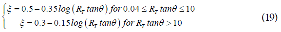
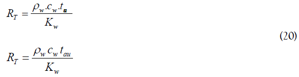
RT is a non-dimensional thermal number used to estimate the value of ξ
The flow stress KAB can be expected from the model J-C and using Von-Misses criteria:
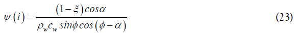
is the average rise of the temperature in the primary shear zone
to which the function of flow stress KAB and the variable ψ(i) can
be calculated as follows:

The variable ψ (i) can be expressed as:
So, can be replaced in Eq.21 in the function of the flow stress KAB and the variable ψ(i) as following:
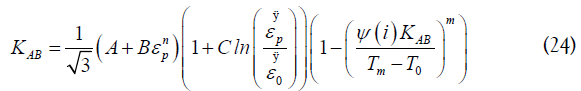
Solving Eq.24 for the flow stress KAB as the unknown variable of
the problem and replacing its value in Eq.22 to compute the rise of
the temperature . The value of the temperature rise is found
by comparing the results of the Eq.17 and Eq.18 by selecting the
minimal amount.
The amount of the temperature in the primary shear zone TAB can be expected in the function of the ambient room temperature
T0 and the rise of the temperature by the Taylor-Quinney
coefficient:

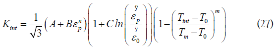
The temperature in the secondary shear zone Tint can be
expected in the function of the ambient room temperature To plus the temperature augmentation in the shear zone plus the
maximum temperature rise in the shear zone TM by the factor of
the temperature variation ζ that can vary between 

Where the flow stress in secondary shear zone Kint is given as follows:
Tchip is the temperature in the chip that can be predictable in the function of the flow stress KAB and material constant and trigonometrically relationship that can be expected as:
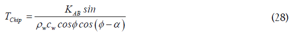
Where the relationship between the maximum temperatures rises in the chip temperature can be expected as:
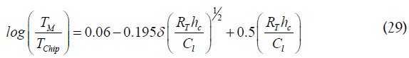
Where the flow stress can be expected as:
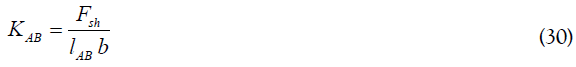
Fsh is the shearing force:
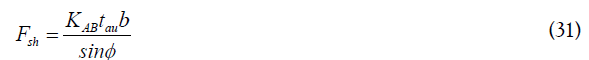
With tau is the incited uncut chip thickness:

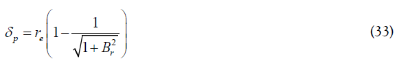
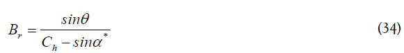
δp is the thickness of the burnishing which is calculated as a function of tool edge radius and the segmentation criterion Br:
All parameters in Eq.35 can be easily determined. Khettabi et al., estimated the shearing force and temperature using the Needelman-Lemonds constitutive equations [27]. In our case, we use the combined J-C and Oxley constitutive equations to estimate the shearing force and the temperature. Finally, we calculate the dust unit given by the following equation:
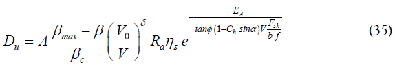
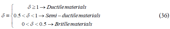
Where A is a proportionality factor of and δ is a parameter which characterizes the aptitude of the material to produce metallic dust. The parameter δ is experimentally determined to obey the following criteria (Eq. 36).
The resultant force R:

The cutting force:

Model Processing
Based on the proposed construction model, MATLAB script is defined according to the flow chart in Figure 2. The input was defined according to the material properties, the cutting conditions and the tools geometry. Compilation was preceded by predicting the shear angle and the chip geometrical parameters. Incrementing the cutting speed and solving the flow stress equation to estimate the temperature value in the PSZ and in the SSZ and finally calculate the dust unit.

Figure 2. Algorithm flow chart for simultaneous estimation of temperature in PSZ and in SSZ, the shear forces and the dust unit
A procedure based on Johnson-Cook equations was developed to adequately describe the material during machining process. This procedure is designed to estimate the temperatures in the primary and secondary shear zones (TAB, Tint), and then the cutting forces are evaluated based on the flow stress. An accurate prediction of the temperature distribution in the cutting tool is highly important. Figure 3 shows the results of the temperature simulation in the primary and secondary shear zone as a function of the cutting speed during dry turning of the 6061-T6 and 7075-T6 aluminium alloy. It is clear that the cutting speed is much related to the temperature level. The chip develops more segments as the cutting speeds increase and therefore the temperature increases. Figure 3 also shows the difference between predicted and measured temperatures. It is clear that the experimental temperature is close to that predicted; the measurement uncertainty is approximately ±25 °C. This difference is produced by measurement uncertainty that result from gain errors, offset errors, differential and integral nonlinearity, noise errors, and cold-junction compensation errors. The model proposed in this study allows us to calculate: stress, strain and temperature in the shear planes during turning. Increased cutting speeds create low shear forces (Figure 4). The shear forces deviation in the PSZ is due to the thermal and mechanical properties combination of the different aluminium alloys presented in Table 1. This deviation is more insignificant when the cutting speed exceeds 400 m/min (Figure 3). The shear forces decrease can be clarified by the Johnson–Cook material model presented by Eq.1. It is evident that when the workpiece temperature increases, the shear forces decreases with the Johnson–Cook constants used in this study. The first zone of the curve in Figure 4 (below 400 m/ min), the shear forces decrease when cutting speed increase. The thermal softening predominates in this case. Due to the thermal conductivity of the aluminium alloys presented in Table 1, the heat generated in the machining cannot be dissipated quickly. This phenomenon increases the temperature of the deformation areas. Consequently, the thermal softening of the work material involves the decrease of cutting force components. In the second zone of the curve in Figure 4 which exceeds 400 m/min, the shear forces tend to stabilize around an average value through the increase in cutting speed.

Figure 3. Temperature simulation results in the primary and the secondary shear zone as a function of the cutting speed for 6061-T6 and 7075-T6 aluminum: DOC= 2 mm, f=0.15 mm/rev.

Figure 4. Shear force variation in the primary shear zone at different cutting speeds: f=0.15 mm/rev and DOC=2 mm.
Prediction of the cutting forces using the orthogonal cutting model in this study is shown in Figsure 5 and 6. The results obtained were validated using cutting force measurement which shows excellent correlations with the data measured experimentally with a 12–17% prediction error. Experience and simulation shows that they are much more sensitive to the feed rate than to the cutting speed: for all equal cutting conditions, increasing the cutting speed is not accompanied by a significant variation in cutting forces (approximately 10% decrease; Figure 5) while the cutting force increases roughly in proportion to the feed rate (Figure 6).

Figure 5. Cutting forces variation as a function of cutting speed (a) for 6061-T6 aluminum alloy, (b) for 7075-T6 aluminum alloy.

Figure 6. Cutting forces variation as a function of feed rate (a) for 6061-T6 aluminum alloy, (b) for 7075-T6 aluminum alloy.
Cutting forces in turning are due to stresses in the PSZ, friction at the flank face and friction at the tool/chip interface. During the machining of the aluminium alloys presented in Table 1, this last contribution appears not important because flank wear was not observed. Cutting forces are at the origin of plastic deformations and therefore of temperature rises which occur during cutting. The shear flow stress in the primary zone is proportional to the cutting forces as a function of the cutting speed. From Eq.38 it follows that the cutting force is more proportional to the shear force in the shear band. So that if the shear force decreases with the increasing temperatures in the primary and secondary shear zones, then the cutting force it is also expected to decrease. As shown in Figure 5. The behaviour showed by the two aluminium alloys in the first zone of the curve is similar. Around 10% reduction in cutting force is observed. However, the curve is same and represents a stability zone for cutting speeds greater than 600 m/min. At very high cutting speeds involves a high strain rate which leads to significant thermal softening of these aluminium alloys. In consequence, the cutting forces have a tendency to increase. This tendency is due to the effects of strain hardening, strain rate and temperature on the materials properties. In addition, it can be seen from the simulation results that the temperature in the primary and secondary shear zones played a significant role in determining the cutting forces, with increasing in the part temperature reducing the cutting forces. The comparison between the aluminium alloys presented in Table 1 shows that 6061-T6 aluminium alloy are distinguished by a relatively high thermal conductivity. This property creates a strong thermal coupling during the machining process, which means that the temperature level will affect significantly the material mechanical properties. Increasing the cutting speed and the shear strain rate in the deformations zones results an increasing in temperature. Simultaneously, the heat flux caused by the plastic deformations process is amplified. Additionally, the evaluation of the aluminium alloys thermal properties to the tool material; the temperature diffusion into the workpiece is limited. As a result, the cutting temperature during aluminium alloys machining is high but a fraction of thermal energy is conducted into the tool. The thermal energy is too low to result in the thermal softening observed in aluminium alloys. The tests showed a diminution in the cutting forces when the workpiece temperature was higher than 250 °C, this behaviour is due to the high strength of 7075- T6 aluminium at high temperatures. We also note, cutting force increase slightly towards the end of the curves due to the reduced shape of the secondary shear zones (decrease of the strain rate and the temperature gradient is lower) (Figure 5).
Figure7: shows the trend of the cutting energy during machining of 6061-T6 and 7075-T6 aluminium alloys. Specific shear energies were calculated based on the measured cutting forces and chip compression ratios. The specific cutting energy is defined as the sum of the specific shear and friction energies. So for each test, the friction energy is smaller compared to the shearing energy. One can see that the shearing energy decreases as the cutting speed increases. On the other hand, an increase in the friction energy is a function of the increase in the cutting speed in the case of 6061- T6, but in the case of 7075-T6, the friction energy is constant for each test. This implies an accentuated reduction in shear energy during machining of 6061-T6 alloy compared to 7075-T6 alloy. This is clearly shown by the effect of cutting speed on shear energy in Figure 7.

Figure 7. Cutting speed effect on cutting energy during machining of 6061-T6 and 7075-T6 aluminum.
Figure 8 shows the comparison between two chips obtained at the 300 m/min and 1144 m/min conditions during orthogonal cutting of 7075-T6 alloy. Images observation shows that the chips morphology, the slip band formation depending on the cutting parameters. Regardless of the cutting speed, the segmental chips are serrated chips called saw-tooth in unstable plastic deformation state.

Figure 8. Chip morphology as a function of cutting speed during machining of 7075-T6 aluminum alloys.
It is evident that the chip segmentation increases with cutting speed during the orthogonal cutting (Figure 9). In addition, the variation in segmentation degree changes as a function of the feed rate. The saw-tooth segments are more clearly formed by increasing cutting speed or feed rate which localizes the strain within the chip. However, a short distance of peak to peak consecutively chips segments is due to the increased cutting speed, while a higher distance of peak to peak is due to a higher feed rate. The reduced peak height and increased shear instability is due to high heat generation in the cutting zone which results in a higher cutting speed. This increased shear instability increases the chip segmentation by reducing in valley height and increasing the tooth height. At low cutting speed, discontinuous chip is formed and at high cutting speed continuous chip is formed. Among others, the result of this segmentation phenomenon proves the chip fragmentation in orthogonal cutting. The errors between the experimentally measured and predicted data are ± 2 segments/ chip.

Figure 9. Cutting speed effect on chip segmentation during machining of 6061-T6 and 7075-T6 aluminum alloys.
Figure 10 shows the different chip morphologies obtained during machining of 6061-T6 and 7075-T6 aluminium alloys at different cutting speeds. According to cutting conditions, chip morphology with different sizes bands is due to the material flow of the workpiece. The chip patterns produced are similar and they are dense and strongly crushed against one another for high speed. The shear bands are more spaced for low cutting conditions. The heterogeneity of the mechanical stresses distribution within the intense deformation zone (primary shear zone) is a known phenomenon. In addition, shear zones observation shows that it is localized over a few μm and it is all the more localized as the cutting speed is high. For 650 m/min, it measures 7 µm while for 1144 m/ min; the sheared zone pitch is around 4 microns. The formation of the chip is accompanied by a localized shear which yields with an extension of cracks towards a catastrophic material behaviour in the chip. Also, other aspects make the chip genesis comprehension more complex by affecting chip formation. Tool engagement in the material creates a stress state depending on the tool geometry and thus causes a crack initiation at external surface of the part. Then there is the shear plane evolution at the point where the crack is initiated towards the tool tip under the dislocations propagation. In the aluminium alloys case, the MgZn2 particles presence will generate heterogeneity in the mechanical stresses distribution in the chip and thus induce deformation bands in directions different from that of the primary shear zone. The stress becomes significant where the crack was already started. The latter continues its path towards the tool tip and thus generates the primary shear zone. This explanation means that it is sometimes possible to find a chips part divided in two (with two crack propagation zones). Finally, the segmentation process is influenced by the dynamic behaviour of the orthogonal cutting system.

Figure 10. Chip morphology evaluation during machining of 6061-T6 and 7075-T6 aluminum alloys.
Figure 11 demonstrates the variation of chip thickness and chip/ tool contact length with feed rate and cutting speed for orthogonal cutting of the two aluminium alloys. The chip thickness decreases with increasing cutting speed and increases with increasing feed rate. On these curves, the same behaviour than for the contact length is observed: a first zone of decrease or increase followed by stationary zone (Figure 11.c and 11.d). It has already been seen previously that increasing the cutting speed implies increasing the cutting temperature. Material softening occurs at elevated temperature and machining forces decreases. As a result, the thickness of the chip decreases. In opposition, the unreformed chip thickness increases as feed rate increases. Also, the cutting force is proportional to the unreformed chip thickness. Shear plane area increases, which lead to an increase in chip thickness due to the increase in unreformed chip thickness. The increase in plastic deformation of material is illustrated by the increase in the chip compression ratio which is a function of the increase in the chip thickness. Finally, the occurrence of segmentation was found to exhibit significant hysteresis with respect to the variations of the chip thickness (Figure 10 and 11).

Figure 11. Evolution of the chip thickness and chip/tool contact length as a function of cutting speed.
Dust Unit curves predicted from the proposed model were compared with the experimental data for orthogonal cutting, they are presented in Figure 12 for the 6061-T6 and in Figure 13 for 7075-T6 as a function of cutting speeds. The experimental results show that dust emission decreases significantly as a function of the cutting speed increasing of both tested alloys. At low cutting speed, dust emission is maximal and equivalent for the two materials tested. The 7075-T6 aluminium alloy generated more than the 6061-T6 aluminium alloy in the same cutting conditions. On the other side, the increase in the feed rate reduces the dust generation. The model was able to predict data for orthogonal cutting of aluminium alloys with a correlation greater than 94.5%. Parameters in Eq.35 can be known or easily determined, only for shear stress and temperature can be estimated with using the J-C & Oxley constitutive equations.

Figure 12. Cutting speed effect on dust emission during orthogonal cutting of 6061-T6 aluminum alloy.

Figure 13. Cutting speed effect on dust emission during orthogonal cutting of 7075-T6 aluminum alloys
These results are in harmony with the study by Khettabi et al., which was discussed in details for different materials [27]. It is concluded that both models indicates a high adjustment to the selected mathematical function. In the model of Khettabi et al., temperature and shear stress can be directly measured and calculated [27]. Temperature measurement will be difficult in the case of certain processes. However, the simulation using an algorithm represents the behaviour of some properties. In this model, the temperature evaluation is possible using Needelman- Lemonds equations. For the shear stress, τAB, is predicted from the cutting forces measured by the following formula:

Where Fx and Fy are the average cutting forces measured, b is the axial depth of cut in mm, and f is the feed rate in mm/rev.
It was observed that for the two aluminium alloys (Figures 12 and 13), show an excellent fit for the two models studied with experimental results. The first model is based on the Johnson-Cook equations combined with the Oxley equations and the second model is based on the Needelman-Lemonds equations. It was also observed that the two models used in this survey have a high correlation with the experimental results obtained (≥ 0.94). This may be attributed to the use of average values for estimating the stress, strain, strain rate, and temperature. In this case, it was not possible to establish a model as being superior to the others. On the other hand, model advantage is that it is not necessary to carry out an experiment to measure a parameter. Temperature and shear stress are directly estimated using the J-C & Oxley constitutive equations.
After examination of the chips morphology, it was observed that, particles located between two shear bands PSZ (Figure 14). Observations using a scanning electron microscope show that the particles generated have a heterogeneous and agglomerated shape. These shapes depend on the material chemical composition and the generation mechanism. Chip formation can indicate different phenomena of fine and ultrafine particles generation during cutting process. The curves analysis in Figure 3, Figure 12 and Figure 13 leads to conclude that increasing the cutting temperature reduces the dust generation. This is explained by the alloy softening caused by the increase in temperature which eliminates the internal stresses obtained by work hardening of chips (Figure 5). Also, it decreases the shear energy between tool/chip (Figure 4, 7); although it increases the segmentations number (Figure 9). In our case, the excess energy generated by these new areas allows certain particles to be separated in order to have a stable energy state between the micro-segments of chips. Most of the dust generation is due to the new areas created by the segmentation because the dust generation is related to the activation energy of the particles. In addition, the dimensionless index (dust unit) is the ratio of the dust mass to the mass of chip removed from the workpiece material. The dust generated in this area at ultra-fine size, it does not influence the dust unit which decreases with increasing cutting speed in the orthogonal cutting. By this analysis, we confirm that particles that have a micrometric size (fine particles) are only generated in the tool/chip and tool/workpiece interfaces. In this case, the increase in temperature stabilizes the energy state of these two lines and the generation of fine particles decreases as the cutting speed increases. Also, increasing the cutting speed decreases chip thickness and tool/chip contact length, but increases segmentation (Figure 9). As the chip thickness and contact length are reduced (Figure 11a and Figure 11c), the new segmentations areas are reaching smaller and smaller. This means that they have a smaller and smaller excess energy, which directly means a reduction in dust generation. So, increasing the temperature in the cutting area helps separate certain types of particles. However, this process should only produce ultrafine particles between the micro-segments. As well, most of the particles generated have a micrometric size in the tool/ chip and tool/workpiece interface. Finally, the dust generation can indicate different phenomena of fine and ultrafine particles generation during cutting process related to thermal energy, shear and plastic deformation.

Figure 14. Fine particles generated in primary shear zones.
The proposed model results and experimental data in this study prove that the dust generations evaluation method is feasible. The J-C & Oxley constitutive equations are proposed to confirm that the method can perfectly searches the parameters of the dust generations mechanism through the model results and experimental data. The spindles power of high speed machining has limits. In order not to have to change the power range, it is necessary to reduce the cutting forces when the spindle rotation speeds are increased. To reduce these forces while maintaining a high chip flow, it is generally chosen to associate low depths of cut with high feed rate to reduce the forces and increase the chip flow. This alternative shows that it is feasible to machine parts at very high speeds, which guarantees high efficiency, high-quality of the parts and without producing harmful dust. Another alternative under any heating of the parts to be machined shows that it is possible to machine parts at medium speeds, which also guarantees high efficiency and without producing harmful dust. All of this gives an opportunity to reduce the dust generation at the source.
This study focuses on the development of predicting model of cutting forces and a temperature that takes into account the effect of strain and strain rate. This prediction model is used to calculate dust generation. The experimental study has showed that the dust generation is closely related to the mechanisms of chip formation. The dust generation can be quantified by the cutting forces and temperatures generated during machining (thermomechanical effect). Therefore, any attempt to evaluation the dust generation must necessarily involve the prediction of cutting forces and temperature generated during the machining. In the second step, the predicted results were compared with the experimental data and also, a comparison was completed between the proposed model and another model based on the Needleman-Lemonds equation. Good agreement was found between the predicted and measured dust generation for the two aluminium alloys tested, where it exhibited high R2 values (above 0.94). The proposed approach can be used in the optimization of the cutting conditions in order to control the dust generation during dry machining.
The following conclusions can be drawn from the present study:
✓ Dust generation is closely related to thermal and mechanical energy.
✓ Temperature variation at the tool/chip interface is due to the variation in higher frictional shear stress at tool/chip interface. Consequently, aluminium alloys need higher frictional energy for sliding to occur, resulting in higher heat generation and increased temperature.
✓ Increasing the cutting temperature greatly reduces dust generation.
✓ Reduction of dust generation is possible at the source under any heating technique of the workpiece.
The authors would like to thank the Mechanics and Advanced Energy Systems Laboratory (LMSEA) and the Products, Processes and Systems Engineering Laboratory (LIPPS) for funding this research study. In addition, the authors also highly appreciated the technical support of the École de technologie supérieure de Montréal and the École nationale polytechnique de Constantine.
Citation: Djebara A, Alliche MA, Khettabi A, Songmene V (2021). Dust Generation Evaluation by a Predicting Model of Cutting Forces and Machining Temperature During Orthogonal Cutting of Aluminum Alloys. J Pollut Eff Cont 9:277. doi: 10.35248/2375-4397.21.9.277.
Received: 13-Feb-2021 Accepted: 25-Mar-2021 Published: 01-Apr-2021 , DOI: 10.35248/2375-4397.21.9.281
Copyright: © 2021 Djebara A, et al. This is an open access article distributed under the terms of the Creative Commons Attribution License, which permits unrestricted use, distribution and reproduction in any medium, provided the original work is properly cited.