Journal of Molecular Imaging & Dynamics
Open Access
ISSN: 2155-9937
ISSN: 2155-9937
Research Article - (2016) Volume 6, Issue 2
Motivation: Breast cancer is a major health problem globally for women causing an appreciable percentage of the yearly female death. Microwave imaging is a promising method in biomedical applications such as breast cancer detection due to its good penetration property, non-ionizing and non-invasive nature which has the potential to be a complementary modality to standard mammography. In this paper, An UWB Microstrip-fed Vivaldi antenna for microwave imaging systems aimed for an early breast cancer detection is developed.
Results: The Vivaldi antenna is designed to operate between 8.821 to 22.30 GHz with dimensions of 44.85 × 25.28 mm that permits good radiation within the frequency range. To achieve UWB performance, Taconic TLC-32 substrate which has relative permittivity of 3.2 has been used to simulate the antenna by using Antenna Magus Software. The simulation results show that the return loss is better than -10dB within the range of 7.143 GHz to 24.60 GHz with the maximum return loss of -37.56 dB at 18.39 GHz. However, due to difficulties in antenna fabrication at higher frequencies, a low frequency of about 2.4 GHz is considered. Antenna measurements presents good radiation pattern that suit medical imaging systems to detect breast tumors. The amount of reflection is also found to be minimum for the antenna design frequency (2.4 GHz) which appears to be -26.34 db.
Keywords: Ultra-wideband (UWB); Microwave imaging; Return loss; Radiation pattern
Microwave imaging for biomedical applications is nowadays of very significant interest, having the potential of providing information about both physiological states and anatomical structures of human tissues. The imaging with microwaves allows non-destructive evaluation of biological tissues due to the non-ionizing nature of microwaves, since changes in the dielectric properties of tissue can be related to their physiological condition. One of the most promising applications deployed is detection of breast tumors [1-4]. This is particularly eligible due to the easy approach of the breast for imaging, as well as the breast anatomy where the fatty tissue (with low loss) has a low attenuation impact on the signal. The contrast in permittivity for different in-vivo tissues (fat, glandular, malign tumor, vascular tissue etc.) is higher for microwaves. It has been reported high contrast of dielectric properties between fibro glandular tissues and tumor tissues in breasts and that it is a non-ionizing method which probably will be rather inexpensive [4].
For this reason, microwave imaging has been developed and has the potential to be a complementary modality to standard mammography. However, it remains a field with many uncharted domains, and microwave imaging techniques need to overcome many challenges and be improved. This includes the enhancement of both more sophisticated hardware (antenna, electromechanical parts, and RF-design) as well as in the software (imaging algorithms) to be considered as a reliable modality for biomedical application.
Vivaldi type is one type of a traveling-wave antenna of the “surfacetype”. Besides being efficient and lightweight, Vivaldi antennas have more attractive features, that they can work over a large frequency bandwidth and produce a symmetrical end-fire beam with appreciable gain and low side lobes [5]. Figure 1 depicts the construction of a Vivaldi antenna.

Figure 1: Vivaldi Antenna (General antenna construction). Where: WO is an output slot width, WA indicates the slot width at radiating area and WE is an input slot width of the antenna.
Antenna design
The immobilized Microstrip-fed Vivaldi antenna design is based on the parameter study so that the wideband performance could be improved in a systematic procedure. The parametric study and design of a microstrip-fed vivaldi antenna is calculated following selection of the substrate material, substrate thickness, antenna length, antenna width and the slotline width. As the electrical length of the antenna increases with frequency the gain increases.
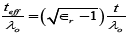
Antenna performance (S11 and pattern) was discussed basing on the effect of varying these parameter values. Particularly, it was found out that through proper change in the design parameters, the antenna resistance could be increased. For the design of the antenna, TLC-32 substrate with a dielectric constant of 3.2 is selected. Effective thickness of the dielectric substrate (teff) is defined as follows:
 (1)
(1)
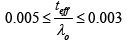
Where, λ0 is the free space wavelength at the center frequency, t is the thickness and ∈r is the dielectric constant of the substrate. The essential criteria for any TSA to possess travelling wave antenna characteristics is defined as:
 (2)
(2)
In order to achieve a transition that has low return loss over a wide frequency band, the impedances of the micro strip line and the slot line must be matched to each other to reduce the reflections. The characteristic impedance of a slot line increases with increasing slot width, so the width of slot line must be selected to be as small as possible to achieve a small impedance value. The width, characteristic impedance, and guided wavelength of slot line are calculated with procedures suggested in [6-8]. Hence the antenna parameters calculated are as given in Table 1.
| Name | Description | Value |
|---|---|---|
| Hf | Flare height | 19.87 mm |
| Lf | Flare length | 37.93 mm |
| Hc | Height of the conductor | 25.28 mm |
| Dc | Cavity diameter | 2.598 mm |
| Smc | Distance form cavity to the centre of the microstrip coupler | 223.9 μm |
| Lmc | Length of microstrip coupler | 2.598 mm |
| Wmc | Width of microstrip coupler | 447.8 μm |
| Lmt | Length of tapered microstrip line | 6.700 mm |
| Wmt | Width of the tapered microstrip line at the port | 1.900 mm |
| Ls | Length of slotline | 447.8 μm |
| Ws | Width of the slotline | 464.8 μm |
| Rs | Radius of the microstrip stub | 2.074 mm |
| Θs | Starting angle of the microstrip stub | 90° |
| Θ | Angle of the microstrip stub | 80° |
| Hs | Substrate height | 790 μm |
| εᵣ | Dielectric constant of the substrate | 3.2 |
| Tanδ | Loss tangent of the substrate | 0 |
| Ft | Factor determining the opening rate of the flare | 83 |
Table 1: Designed parameters of the antenna.
Micro-strip-fed Vivaldi antenna layout
Method: All Tapered-slot antennas are frequently etched with other components onto the same dielectric substrate. The Microstripfed Vivaldi has the advantage over other TSA that it can easily be integrated in the circuit. The microstrip to slotline transition is realized by etching the slotline on one side of a substrate. On the opposite side of the substrate, a microstrip line crosses below and perpendicular to the slotline. After crossing below the slotline, the microstrip line is flared to form a radial stub which acts as a wideband, virtual short circuit. Antenna Magus has taken care of this non-trivial design process and includes the designed feed section detail in the antenna model.
The main field of the project is a research approach to select the most optimum antenna that meets requirements of microwave imaging. Antenna Magus and CST Microwave Studio Stimulator are proposed for simulation purpose. This software is given great flexibility in tackling a wide application range multi-frequency antennas, it offers both low frequency operation as well as a high frequency bandwidth and operating bandwidth. Imaging systems need to work on different operating frequency and pattern. There are many methods of designing multi-frequency antenna.
The proposed model is designed using the guided wave traveling in the slot transmission line (slotline) and the plane wave, which is radiated. This transition is achieved by a gradual tapering of the slotline. In Vivaldi with a microstrip feed, the microstrip line is printed on a substrate and the tapered slotline is etched on the ground plane below the microstrip. A few parameters are of great importance for satisfactory wideband performance: The length and the width of the tapered slot line: to achieve the traveling wave mode of radiation, the slot length and width generally needs to be greater than and, respectively (Figures 2-4) [9].

Figure 2: Top view of the Microstrip-fed Vivaldi antenna.

Figure 3: Bottom view of the Microstrip-fed Vivaldi antenna.

Figure 4: Image of the Microstrip-fed Vivaldi slot antenna.
Simulation results
The nanoscope Simulations were done through Antenna Magus Software with Vivaldi design dimensions as described. Various simulations were done to better tune the operating frequency required for microwave imaging that it should be an Ultra-Wide-Band. The results represent final simulations (Table 2).
| Name | Description | Value |
|---|---|---|
| Fmin | Minimum frequency | 8.3 GHz |
| Name | Substrate: The substrate name. | TLC-32 |
| Manufacturer | Substrate: The substrate manufacturer. | Taconic |
| Substrate Thickness | Substrate: The thickness of the substrate. | 790 μm |
| Relative Permittivity | Substrate: The relative permittivity of the substrate. | 3.2 |
Table 2: Summary of the substrate chosen to fit into microwave imaging systems.
Estimated performance charts
Human In (Figure 5), the simulated variation of the antenna input impedance versus frequency of the proposed Microstrip-Fed Vivaldi antenna can be seen. At the operating frequency of approximately 8.3 GHz, the average value of the resistance (real part) is about 140 Ohms and the average value of the reactance (imaginary part) is approximately 40-Ohms which gives the adequate input impedance matching at the desired resonant frequency.

Figure 5: Simulated input antenna impedance (Ohm) vs. frequency.
The input impedance is as summarized in the following (Table 3):
| Peak real impedance @ frequency | 138.1 Ω @ 7.730 GHz |
| Real impedance @ zero-crossing frequency | 138.1 Ω @ 7.752 GHz |
| 42.84 Ω @ 9.259 GHz | |
| 74.41 Ω @ 9.729 GHz | |
| 28.79 Ω @ 11.59 GHz | |
| 53.98 Ω @ 12.24 GHz | |
| 24.12 Ω @ 13.54 GHz | |
| 61.84 Ω @ 14.96 GHz | |
| 37.31 Ω @ 15.64 GHz | |
| 84.80 Ω @ 17.03 GHz | |
| 47.87 Ω @ 18.33 GHz | |
| 63.59 Ω @ 18.81 GHz | |
| 26.74 Ω @ 22.22 GHz | |
| 114.9 Ω @ 26.72 GHz 17.30 Ω @ 31.59 GHz |
|
| Mean real impedance | 48.66 Ω |
| Mean imaginary impedance | -3.925 Ω |
Table 3: Input impedance versus frequency.
The reflection coefficient (|S11|) (dB) of the proposed antenna provides a good matching input impedance with a good return loss of less than -10 dB at operating bandwidth of (7.143-24.60) GHz, and having the reflection coefficient of -37.56 dB at 18.39 GHz as depicted in Figure 6.

Figure 6: Reflection coefficient chart of a Microstrip-fed Vivaldi antenna.
The minimum voltage standing wave ratio, VSWR of 1.02 is observed at frequency of 18.39 GHz, and having a VSWR of 2 at a bandwidth of approximately 7-24 GHz indicating low power return at the frequency of operation.
Table 4 is a summary of Smith Chart simulated results of Microstrip- Fed Vivaldi Antenna.
| Frequency at which VSWR = 2 | 7.175 GHz |
| 8.786 GHz | |
| 10.09 GHz | |
| 11.39 GHz | |
| 13.21 GHz | |
| 13.86 GHz | |
| 22.43 GHz | |
| 23.15 GHz | |
| 24.69 GHz | |
| Minimum VSWR value | 1.027 |
| Reference impedance @ port 1 | 50 Ω |
Table 4: Summary of Smith chart simulated results of Microstrip-Fed Vivaldi Antenna.
Antenna testing and evaluation
The designed antenna is fabricated and tested. It is important to note the difficulty involved during antenna fabrication and when taking its measurements. Since several expensive test components are needed, along with a suitable test component to test the antenna at higher frequency bandwidth, thus the frequency of operation designed and simulated is lowered for ease of fabrication. In this case, a lower frequency range of 2.4 GHz is included. The test component used for antenna testing is (the HP 8753D Network Analyzer). Because of this, simulation results were used to compare actual test results for accuracy at higher frequencies and results after fabrication indicates better results at lower frequencies. The following test results shows data involved a 2.4 GHz Microstrip-Fed Vivaldi Antenna using FR-4 substrate with 4.4 dielectric constant. The plot of Figures 7a and 7b, shows the top and bottom geometry of the antenna along with its dimensions.

Figure 7a: Vivaldi Antenna geometry (top and bottom views).

Figure 7b: Vivaldi Antenna geometry (top and bottom views).
Antenna specifications
Frequency of operation = 2.4GHz
FR4 Material dielectric constant = 4.4
Thickness=1.6 mm
Total dimension=85.8 mm ×130 mm
The design of proposed antenna design is as shown below (Figures 7a and 7b).
CAD views: Coaxial feed (shown by green line) is chosen as per 50- Ohm line. The coaxial feed is given 62 mm on x- axis which gives good impedance matching.
The gain of the antenna under test is measured in the bore sight direction. The experimental setup to determine antenna gain is similar to the radiation pattern measurement setup. After fabrication, the antenna is found to have a gain of 2.5 dB at the frequency of operation 2.4 GHz as depicted in Figure 8.

Figure 8: Gain of E-patch of the Microstrip-fed Vivaldi antenna.
Scatter parameter S11 (The return loss) for the antenna is as depicted by Figure 9. Ideally, the amount of reflection should be at a minimum for the antenna design frequency (2.4 GHz). Taking a look at the illustration, the least amount of reflection occurs at exactly 2.4 GHz, in which the return loss at minimum of -26.34 dB.

Figure 9: Return loss.
From the graph of Figure 10, the minimum voltage standing wave ratio, VSWR of approximately 1.1 is observed at frequency of 2.4 GHz, and having a VSWR of below 2.4 at a bandwidth of approximately 2.2- 2.8 GHz indicating low power return at the frequency of operation. Figure 11 is plot representing how 2D radiation pattern would appear. Test results indicates a unidirectional (directive) radiation pattern as per the requirement of antenna suitable in microwave imaging for breast cancer detection.

Figure 10: VSWR chart.

Figure 11: 2D-Radiation pattern.
The results of the antenna simulation and test results after fabrication were overall very pleasing. Development of antenna for microwave imaging systems for breast cancer detection project was a research based in which various antennas were designed and simulated. Among Microstrip patch antenna and fractal antennas, Microstrip-Fed Vivaldi antenna was found to present the most suitable results for imaging systems. It was quite easy to design, simulate and fabricate. The fabrication and testing phase of the project was the most difficult. The difficulty in taking measurements that was significantly underestimated. The major setback during the entire period of the project was the fact that our labs are not furnished with all the necessary antenna test equipment that we can fabricate the antenna at higher frequency as expected after simulations. It eventually was discovered that some antenna measurements including the frequency of operation could be made with reasonable accuracy with the current test equipment and environment available. Mainly, it was possible to measure the impedance match of a test antenna, along with an abstract plot of the characteristic of the antenna including radiation property, gain, return loss and VSWR. Taking into consideration the amount of time and hard work this project required, the results are extremely pleasing. The department is now in a reasonable position to develop a complete antenna design at higher frequencies when equipment are available in our lab.
Both TLC-32 and FR-4 substrates offers some amount of flexibility making them suitable for breast cancer detection to easily detect breast tissues. These substrates were chosen based on availability in the market.
It is recommended that for enhancing bandwidth and reducing return loss, antenna can be designed by using different flexible substrates when available. Antenna performance can also be altered by using different feeding techniques.
This project research and publication were funded by the Research Council of Oman, TRC as a part of “Faculty Mentored Undergraduate Research Award Program, FURAP”. The research work is also supported by Middle East College, Department of Electronics and Communication Engineering, Al'Rusaiyl. Any discussion, results, findings, conclusions or recommendations expressed in this report are those of the authors.
The authors would like to thank the Research Council of Oman, TRC and Middle East College for funding this research work with whom all valuable resources to support this work have been possible.
Specifically, they would like to express gratitude to Ms. Sreelakshmi T. Goopinathan and Dr. Elizabeth Rufus for their exemplary guidance and constant encouragement to research on this area.