Journal of Geology & Geophysics
Open Access
ISSN: 2381-8719
ISSN: 2381-8719
Research Article - (2013) Volume 2, Issue 3
Geological characterization of a heterogeneous alluvial channel aquifer was conducted using outcrop mapping and analysis of lithological logs from 15 boreholes drilled at the site. The study was aimed at developing a preliminary hydrogeology conceptual model. A total of 12 lithological samples were tested in the laboratory using falling head permeameter to determine the hydraulic conductivity of each unconsolidated lithology unit. Shale and calcrete outcrops were observed on the study site. Outcrop mapping on the site also indicated the presence of a contact plane between the overlying unconsolidated sediments and the shale of the underlying bedrock where a groundwater discharge zone has been created. Geology logs show that the alluvial channel aquifer comprises of three distinct layered unconsolidated sediment materials (calcrete, clay-silt, sand-gravel deposited formations) that overlie low permeable shale formation. Geological lithology revealed the spatial variation in the nature and type of unconsolidated sediments deposits between boreholes that can influence groundwater occurrence and flow in the aquifer system. The gravel-sand aquifer layer that consists of medium to large pebbles is conceptually the main hydraulically conductive unit with an average laboratory determined hydraulic conductivity of 8.5 m/day. Hydraulic gradient calculated using a combination of boreholes ranges from 0.013-0.022.
Keywords: Alluvial aquifer, Conceptual model, Geological characterization, Heterogeneous aquifer, Hydrogeology, Outcrop mapping, Unconsolidated sediments
A considerable part of today’s farmers in Southern Africa rely on groundwater abstraction from alluvial aquifers for irrigation purposes during the dry and winter planting season. In Southern Africa, groundwater from alluvial aquifers located along both ephemeral and perennial rivers is used to meet agricultural and domestic requirements [1]. Ephemeral rivers are more common in Southern Africa due to extended periods (>9 months) without significant rainfall events [2]. During these dry periods farmers rely heavily on groundwater.
Alluvial aquifers are often targeted for production usage in agriculture since large quantities of water can be potentially abstracted from the system. In Southern Africa, the alluvial river channel aquifers comprises mostly of sedimentary deposits, composed of various lithological components such as clay, silt, calcrete and sand. The lithological components are highly variable in physical and chemical properties which are a function of the depositional environment and sedimentary processes. Research indicates that the transport of groundwater and solutes is depended on the relevant chemical and physical properties of specific lithological component in aquifer systems [3].
Most alluvial channel aquifers are often characterized by shallow water table conditions and highly conductive gravel-sand hydrogeologic units. Such hydrogeological characteristics although good for groundwater yield and abstractions, also present suitable conditions for contaminant access and transportation in the aquifer. In general, three typical hydrogeological problems can be associated with alluvial aquifers. Firstly, it is the infiltration of nitrate contaminants into the aquifer system from fertilizers used in crop production [4]. Secondly, over abstraction from the aquifer causing an increase in the ingress from the river bed and finally the dewatering of the alluvial aquifer can negatively affect the riparian vegetation [5]. Most of these problems that can arise in alluvial aquifers require a good understanding on the spatial variation of physical geological properties of the system, since these factors have a considerable influence on the groundwater flow and transport processes.A number of hydrogeological studies have been conducted on alluvial channel aquifer in Southern Africa [2,6-8]. Most of the studies have focused on assessment of the potential yield and sustainability of the aquifer with no effort being devoted to the spatial variation of geological aquifer materials and their influence on hydrogeological properties. Geological characterization provides the best way to understand the nature and physical properties of the subsurface geological aquifer materials. Coarse-grained alluvial aquifers are typically regarded as close to homogeneous porous media when estimating hydraulic and transport parameters. Groundwater and transport flow through these unconsolidated sediments is however greatly controlled by internal aquifer material architecture [9]. It is therefore important for practicing hydrogeologists to be able to understand and describe spatial variations of aquifer materials using conventional site characterization tools.
The study area is located in the Modder River catchment, downstream of the Krugersdrift Dam in the city of Bloemfontein, Free State Province in South Africa (Figure 1). The study area is surrounded by farms that are mainly characterized by maize crop production. A weir has been built downstream of the Krugersdrift dam for flow measurements. However, it is large enough to impound water for irrigation and recreational fishing.
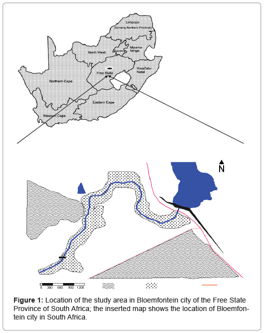
Figure 1: Location of the study area in Bloemfontein city of the Free State Province of South Africa; the inserted map shows the location of Bloemfontein city in South Africa.
The study area is generally characterized by arid to semi-arid climate with long periods of low rainfall events. On average, the area receives about 540 mm to 750 mm of precipitation per annum, which is often associated with heavy thunderstorm activities. The riparian vegetation alongside the Modder River banks comprises of tall thorn trees, small Bushveld shrubs and thick grasses. Surface topography slopes towards the Modder River and natural groundwater flow should conceptually follow the same trend.
This paper is part of a broader study being conducted in South Africa with the aim of assessing groundwater and surface water interactions between aquifers and river systems. This article describes the application of outcrop mapping and percussion drilling to characterise a heterogeneous alluvial aquifer in a geological setting. In order to evaluate the influence of the local geology on the aquifer, a systematic investigation was done into the composition of the lithology, outcrop mapping and estimation of hydraulic conductivity for each of the components.
Regional geology
The general of the study area is characterized by sandstone and mudstone outcrops of the Beaufort Group located in the Main Karoo Basin. The Main Karoo Basin overlies the central and eastern parts of South Africa. The sediments of the lower part of Beaufort Group (Adelaide Sub-group) within the general area of the study site comprises unconsolidated quaternary deposits of calcrete, silt-clay and gravelsands the shale bedrock. Figure 2 shows the location of the Karoo Main Basin in South Africa and neighboring countries. A geological cross section showing from George to Johannesburg (See Figure 2 for the locations of towns) cutting through the Cape Fold and Karoo Main Basin is shown in Figure 3.
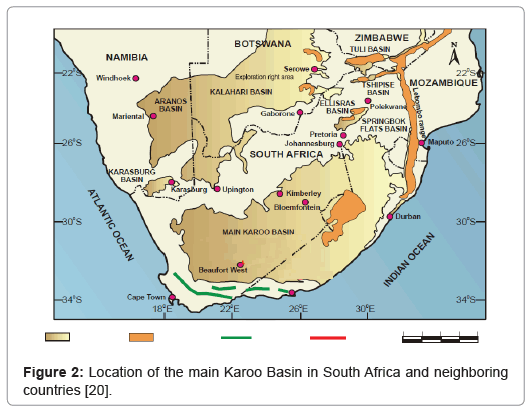
Figure 2: Location of the main Karoo Basin in South Africa and neighboring countries [20].
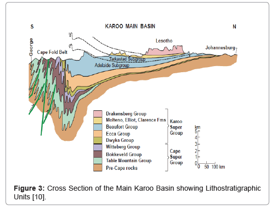
Figure 3: Cross Section of the Main Karoo Basin showing Lithostratigraphic Units [10].
Adelaide subgroup: The gravel-sand and clay-silt quaternary deposits from the Adelaide Subgroup of the Beaufort group occur along major river valleys in the Karoo basin. The Beaufort group deposition history represents a change from marine to fluvial (riverine) environments. The unconsolidated sediments are generally permeable to groundwater flow and can often form extensive aquifers with good yield. Regional geology description will therefore focus on the Adelaide Subgroup [10]:
• The Adelaide Subgroup attains a maximum thickness of about 5000 m in the Southeast and decreases rapidly to about 800 m in the center of the Karoo basin.
• In the Southern and central parts of the basin, the Adelaide consists of alternating bluish-grey, greenish-grey or grayishred mud rock and very fine to medium grained sandstones. The northern part of the basin is characterized by very coarse sandstones.
• The Beaufort Group (Adelaide subgroup) sediments are highly indurate with chlorite and sericite. Common minerals include carbonate, iron oxides, calcite, feldspar and quartz.
Quaternary deposits: According to Woodford and Chevallier [10], quaternary deposits are a common characteristic along the major rivers in the Karoo basin. Deposits on the bed of braided streams consist mainly of coarse sediments, conglomerates and patches of finer material on their banks. Meandering streams on the other hand deposit mainly fine-grained sand, mudstone and siltstone. Gravel-sand and alluvium-silt deposits are often found along several river courses and along the channel zones. The deposition of sediments in the fluvial environments takes place either by vertical or lateral accretion resulting in the formation of three major deposits [11]:
• Flood basin deposits which comprises largely of fine-gained deposits formed during heavy floods when river water flows over the levees into the flood basin. Flood deposits are mostly made up of uniform laminated mud’s with intercalations of silt and in some instances sandstone.
• Channel deposits that are formed mainly by the action of river channels, these include lag, point bar, and channel fill deposits.
• Bank deposits are formed on the banks during floods and, it include crevasse splay and levee deposits. The crevasse splay and levee deposits are typically characterized with thin alterations of sandy and silty layers.
Hydrogeologists are concerned with understanding the subsurface geological aquifer properties and geological characterization provides the best means to achieve this objective. Geological characterization can be achieved using different tools depending on the investigation objectives and the available or accessible equipment. Convectional tools and techniques such as outcropping mapping, drilling, coring and borehole geophysics are commonly used. Drilling of boreholes remains the principal means of geological characterization for most subsurface investigations [12]. Valuable information on the physical and chemical properties of the geological material underlying the site can be obtained from visual observations and analysis made on the borehole geological logs.
In general, real aquifers are not directly accessible for investigation to derive aquifer parameters and drilling boreholes provides an appropriate solution. The contribution of outcrop mapping to understanding of the subsurface geology should never be underestimated. An outcrop composed of a similar stratigraphy and lithologies as the aquifer may be viewed as a representation of the actual aquifer [13]. Accessible outcrops can be examined for spatial geological geometries and structures at a smaller scale investigation. However under some circumstances, outcropping can also signify the surficial appearance of aquitards. Geological characterization was achieved through outcrop mapping, analysis of drilling geological logs and laboratory hydraulic conductivity testing. A total of nine boreholes have been drilled on the study site and five other boreholes are drilled on the background of the site (Figure 4). Hydraulic conductivity of the unconsolidated aquifer sediments was determined using the falling head permeameter [14].
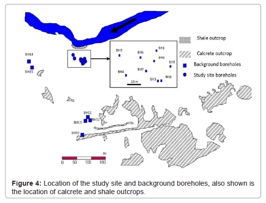
Figure 4: Location of the study site and background boreholes, also shown is the location of calcrete and shale outcrops.
Outcrop mapping
An outcrop is that part of a rock formation or mineral that appears at the earth’s surface. In general, outcrop mapping involves the identification and description of the rock formations and minerals that are exposed to the earth’s surface. Detailed outcrop mapping can include inspection of structural geological features and their orientations.
Outcrop mapping is often conducted in the vicinity of the study area before borehole drilling explorations as part of initial site survey. Prior to borehole drilling one has to plan for the type of drilling equipment and borehole construction logistics. The general knowledge of site geology acquired through outcropping mapping is pivotal. Detailed outcrop mapping can still be conducted after borehole drilling to confirm the validity of borehole geological logs. In general, the analysis of borehole logs obtained through the percussion drilling method is a subjective process due to the mixing of the drill cuttings. The subjectivity and erroneous interpretation of borehole logs from percussion drilling does not put their usefulness into doubt but saves to highlight the need for the use of complimentary approaches. A comparison of borehole logs to rock outcrops can assist in the identification and description of the subsurface lithology. In this study, outcrop mapping was conducted over an area of approximately 900 x 600 m2 through the observation and identification of outcropping rocks. The outcrops were classified based on the lithology, weathering and fracturing.
Borehole drilling
Boreholes were drilled using the air rotary percussion drilling method. The drilling depth was determined based on the initial site understanding which had been gained through outcrop mapping. Poly Vinyl Chloride (PVC) pipes has been used to case the boreholes. The boreholes were cased to prevent collapsing of the unconsolidated sediments. Borehole geological logs were analyzed through visual inspection to identify and describe the lithology per each meter drilled. Figure 3 indicates the specific location of each borehole and Table 1 shows a summary of important drilling information. All boreholes were drilled to a diameter of 160 mm.
| Borehole name | Borehole Depth [mbgla] | Casing depth [mbgl] and description | Main water strike [mbgl] | Water level elevation [mamslb] | Surface topography [mamslb] |
|---|---|---|---|---|---|
| BH1 | 42.00 | 24 - Closed, sealed with concrete | 5.00 | 1237.67 | 1240.99 |
| BH2 | 24.00 | 12 - Closed | 5.50 | 1238.62 | 1241.28 |
| BH3 | 24.00 | 12 - Closed | 7.00 | 1239.14 | 1241.77 |
| BH4 | 24.00 | 12 - Closed | 6.00 | 1238.30 | 1241.55 |
| BH5 | 12.00 | 8 - Fully perforated | 6.50 | 1239.22 | 1241.33 |
| BH6 | 12.00 | 8 - Fully perforated | 6.00 | 1239.20 | 1241.34 |
| BH7 | 12.00 | 8 - Fully perforated | 7.00 | 1239.36 | 1241.58 |
| BH8 | 6.00 | 6 - Fully perforated | 3.50 | 1239.27 | 1241.77 |
| BH9 | 12.00 | 8 - Fully perforated | 7.00 | 1238.87 | 1241.52 |
a – meters below ground level, b – meters above mean sea level
Table 1: Information of the boreholes drilled at the study site.
Hydraulic conductivity tests
Hundred grams of disturbed samples were randomly collected from calcrete, alluvium-silt, clay and gravel-sand unconsolidated formations intersected by boreholes (BH1-BH9) drilled at the study site. A total of three samples were collected from each unconsolidated lithology unit. Samples from different boreholes were then thoroughly mixed to obtain a representative sample of each lithology. The representative samples of lithologies were analyzed for hydraulic conductivity in the laboratory using the falling head permeameter [14]. Prior to the analysis, the representative samples were repacked in the laboratory in an attempt to replicate their original conditions.
Outcrops
Patches of calcrete outcrops were observed in the vicinity of the study site (Figure 4). The appearance and formation of the outcropping calcrete is mainly attributed to carbonate precipitating above shallow fluctuating water table. The calcrete outcrops completely disappears towards the Modder River. Close to the river, calcrete formation is found beneath the ground surface.
Shale outcrops were also observed along the Modder river bank adjacent to the site (Figure 4). The shale formation is the bedrock on which the overlying unconsolidated sediments have been deposited. The average thickness of the unconsolidated overlying sediments is approximated to be about 10 m above the shale bedrock. Based on outcrop mapping results, PVC casing pipes had to be acquired prior to the drilling in order to prevent boreholes from collapsing on the upper unconsolidated section. A hypothesis that a deep fracturedrock aquifer system existed on the site was built after observation of weathered shale outcrops. It is always difficult to infer the existence of weathered and fractured-rock aquifer based on observations made solely on outcropping rocks. Naturally, outcropping rocks are exposed to atmospheric conditions with various agents of weathering that can result in fracturing; hence such observations should be treated with caution.
The contact plane between the overlying unconsolidated sediments and the shale of the underlying bedrock has formed a preferential flow path for groundwater thus creating a discharge zone at the river bank. Bedding plane fractures between the contacts of different sedimentary formation of the Karoo basin are often characterized by high transmissivities [15]. In such instances, the preferential flow paths can accelerate the movement of both groundwater and contaminants.
Geological logs and borehole construction
Alluvial channel aquifer:
BH1 borehole: BH1 is the deepest borehole at the site (Figure 5). The borehole was drilled to 42 mbgl on the hypothesis that the site consisted of two aquifer systems. The first aquifer was system was believed to be a perched gravel-sand shallow aquifer overlying a deep aquifer located in the shale bedrock. The deep shale aquifer system was believed to be heavily fractured given the high prevalence of fracturedrock aquifers in the Karoo sediments [16]. The subsurface in the vicinity of BH1 comprises of calcrete, clay-silt and gravel-sands unconsolidated sediments overlying the shale bedrock (Figure 5).
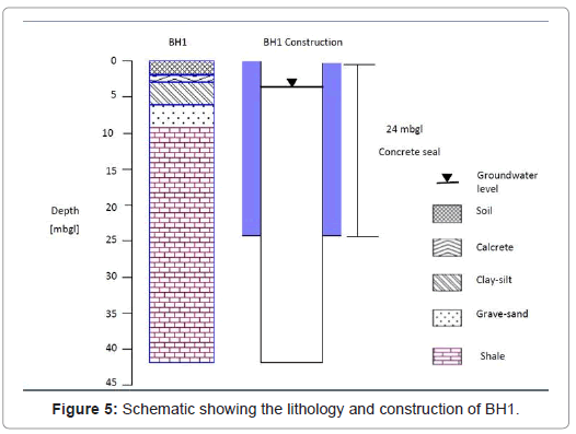
Figure 5: Schematic showing the lithology and construction of BH1.
After hitting the first water strike at 5 mbgl, it was only imperative to drill deeper with the hope of reaching the deep fractured aquifer system. There was however no visible water strike encountered from 5 to 42 mbgl to infer the existence of a deep aquifer system at the site in the shale formation. The hypothesis of a fractured deep aquifer system persisted and there was need for further investigations. An attempt was made to seal off the first 24 mbgl section of BH1 using a concrete mix (Figure 5). The objective of sealing was to isolate the hypothesized deep aquifer in the shale formation from the shallow aquifer system.
Other boreholes: The 12 m deep boreholes were drilled to fully penetrate the gravel-sand layer aquifer layer of the site. The boreholes were cased with perforated PVC pipes for the first 8 mbgl to prevent collapsing of the unconsolidated sediments. All the 12 m deep boreholes with the exception of BH5 intersect calcrete, clay-silt and gravel-sands unconsolidated sediments (Figure 6). Borehole BH5 lithology consist of soil and fine alluvium-silt. The most likely explanation is that BH5 is situated in a former flood plain characterized by fine sediment deposits. The unconsolidated sediments of calcrete, alluvium-silt, clay and gravel-sands conceptually form the site aquifer systems.
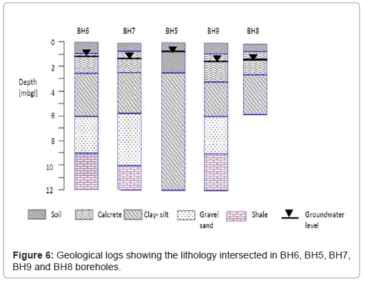
Figure 6: Geological logs showing the lithology intersected in BH6, BH5, BH7, BH9 and BH8 boreholes.
Borehole BH8 is the shallowest borehole at the site. The borehole intersects calcrete and alluvium-silt unconsolidated sediments (Figure 6). Borehole BH8 had its main water strike at 3.5 mbgl which strongly suggests the presence of a shallow water table aquifer in alluvium-silt layer. The borehole was drilled to assess the influence that the overlying calcrete and alluvium-silt potentially has on the groundwater flow and transport processes at the site. Figure 7 shows the subsurface lithology intersected in the boreholes that were drilled to 24 m depth.
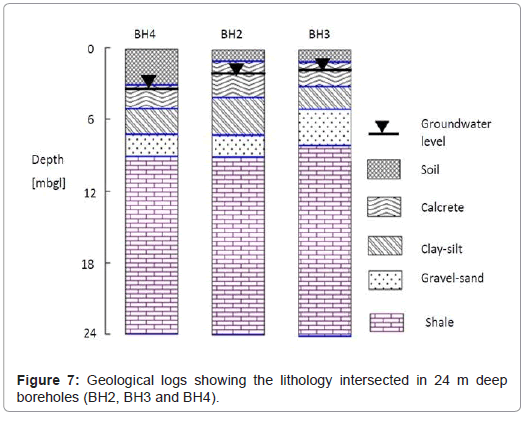
Figure 7: Geological logs showing the lithology intersected in 24 m deep boreholes (BH2, BH3 and BH4).
In all the boreholes the depth to the water is above the water strikes (Table 1). The hydraulic head in this layer determine the level of the water level rise in boreholes drilled into the formation or to those that are hydraulically connected to the formation irrespective of the main water strike positions.
Background geology: The background geology generally consists of soil, clay-silt and calcrete unconsolidated deposits overlying the shale bedrock with the exception of BH14 that does not intersect clay-silt materials (Figure 8). Borehole BH14 is generally located closest to the riparian zone and it intersected a thick soil layer closer to the ground surface. Closer to the riparian zone organic matter from decaying vegetation potentially enhances the formation of soil materials. The geological logs (Figure 8) indicate that the shale bedrock is a continuous formation that covers the background aquifer and the alluvial channel aquifer.
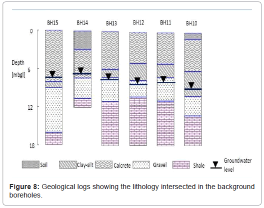
Figure 8: Geological logs showing the lithology intersected in the background boreholes.
The geological material of the adjacent terrestrial is generally similar to the alluvial aquifer lithology. There is however a huge difference in the thickness of the overburden unconsolidated sediments and subsequently the depth to the water levels (Table 1). The terrestrial land is characterized by thicker unconsolidated vadose zone sediments and deep water levels as compared to the shallow alluvial channel aquifer. The presence of thick unconsolidated sediments on the terrestrial background aquifer can be attributed low erosional effects when compared to the riparian zone.
Lithological hydrofacies: The term hydrofacies is used to describe a sediment hydrogeological unit with similar characteristic of groundwater hydraulic and storage properties. According to Klingbeil [13], hydrofacies are formed under comparable conditions and this often leads to similar hydraulic properties. Based on visual observations on grain size and texture analysis the sediments at the Krugersdrift study site were grouped into four separate hydrofacies (Table 2).
| Hydrofacies | Geologic interpretation | Drilling descriptions | Texture |
|---|---|---|---|
| Calcrete | Chemical deposition | Calcareous soils | Fine grained |
| Whitish Silt-clay, and alluvium-silt (Muddy sands) | Flood plain deposition | Silt-clay, calcrete and alluvium-silt | Fine to medium grained |
| Gravel-sands | Channel depositions | Gravel packing | Gravel and medium to coarse sands, small to medium pebbles |
| Shale | Bedrock | Grey old and fresh | Fine grained |
Table 2: Properties of major sediment hydrofacies at observed at the study site.
Table 3 shows the hydraulic conductivity (K) values of the unconsolidated aquifer sediments determined in the laboratory using the falling head permeameter. A representative K value of each unconsolidated formation was calculated using harmonic mean of the 3 samples per each lithology unit. The falling head permeameter results indicate that the gravel-sand aquifer layer has the highest K of 8.5 m/ day. The alluvium-silt layer conceptually forms the low permeable shallow aquifer system with hydraulic conductivity in the order of 1.0E-3 m/day. The low permeable upper calcrete layer potentially creates semi-confining layer to the shallow alluvium-silt aquifer. The clay layer that confines the gravel-sand layer from the shallow aquifer has the lowest hydraulic conductivity in the order of 1.E-5 m/day. The shale consolidated sediments was classified as impermeable since the formation was observed to be dry during the drilling.
| Lithology unit | K [m/day] |
|---|---|
| Calcrete | 1.0E-04 |
| Alluvium-silt | 1.0E-03 |
| Clay | 1.0E-05 |
| Gravel-sand | 8.5 |
Table 3: Hydraulic conductivity values of the unconsolidated aquifer sediments determined using the falling head permeameter.
Calcrete: Calcrete is a sedimentary rock formed through the hardening and lithification of calcified regolith. During the formation, grains of different formations are cemented by calcium carbonates to form the calcrete rock. The site is located in an arid to semi-arid region and in such places calcrete is usually formed as a weathering product of dolerite [10]. However, at the local site scale, the following processes are more applicable in explaining the presence of calcrete at the ground surface and at shallow depth.
When carbonate precipitates above a fluctuating shallow water table, calcrete is formed very close to the earth’s surface. The process typically occurs in arid regions where capillary action process has great potential to bring moisture to the surface. The presence of calcrete outcrops in the background terrestrial land is evidence to infer the prevalence of this process. Shallow and fluctuating water table most likely contributed to the formation of calcrete at the earth’s surface through capillary action. Calcrete formation dominates the background site geology between 0.3-2.5 mbgl. Uptake of water by plants potentially leaves behind dissolved calcium carbonates that can precipitate to form calcrete [17].
On the other hand, carbonate minerals can also be leached and transported from upper soil horizons into the lower horizons. Precipitation of carbonate and dolomite minerals occurs in the lower horizons when the saturation is reached resulting in various forms of calcrete [17]. In arid to semi-arid areas, the removal of water by evapotranspiration greatly contributes to calcite chemical saturation conditions and hence the formation of calcrete. The study site is a semiarid area and the existence of calcrete formation at lower horizons (0.3-2.5 mbgl) is mainly attributed to the leaching down of calcium carbonates from upper horizons.
The occurrence of calcrete in different forms and depth in the sediments possibly represent different ages and or stages of remobilization [17]. Although the permeability of calcrete is low because of small particle sizes and tight packing, they have high groundwater storage potential. Dissolution of calcrete often results in preferential flow paths that can increase the groundwater recharge of the aquifer from direct precipitation. The spatial variability in depths and thickness of calcrete sediments can have important influence on the groundwater recharge variation across the site.
Clay-silt sediments: Clay-silt sediments were deposited by the old river channel on top of the gravel-sand deposits overlying the shale low permeable bedrock. However the whitish color of the clay-silt sediments indicates the accumulation of calcium carbonate minerals from the upper calcrete layer into the lower horizons. This type of soil is collectively referred to as calcisols soils. Calcisols soils are characterized by medium to fine textured materials with good water holding capacities. Due to their medium to fine texture properties, the term clay-silt is used for the calcisols soils. Calcisols soils are formed when calcium carbonates (CaCO3) accumulates and precipitates in the deep soil horizon forming a calcic horizon [18]. In general calcisols soils are formed due to the following processes [18]: Calcium carbonates accumulate in the deep soil horizon forming a calcic layer. Calcium carbonates often accumulate through diffuse enrichment of soil matrix or as discrete concentrations. The CaCO3 accumulates precipitates in the deep soil horizons leading to the formation of a calcic horizon. At the site, the accumulation of CaCO3 in the deep soil horizons is imminent given the existence of calcrete layer between 2-4 mbgl. Leaching of the overlying calcrete by infiltrating rain water over long period of time result in the build-up of CaCO3 in the lower horizons is directly responsible for the formation of whitish silt-clay at the study site.
Gravel-sand deposits: The gravel-sand hydrofacies mainly consist of coarse sand and gravel deposited pebbles of assorted formations that represent channel deposits of different depositional environment. Gravel-sand deposits are a common phenomenon along most of the major alluvial rivers. In the European quaternary sedimentary basins, gravel-sand deposits of braided alluvial stream constitute the most extensive and productive aquifer units [9]. From a hydrogeology perspective, detailed understanding of the distribution and connectivity of the most hydraulic zones in an aquifer is critical. The gravel-sand layer mainly comprises of quartz minerals and small to large deposited pebbles. The gravel-sand hydrofacies are typically characterized by high hydraulic conductivities (Table 3).
Spatial variation in sizes and packing of gravel-sand aquifer materials at the site is the most important factor contributing towards aquifer heterogeneity. Physical properties of the gravel-sand aquifer materials around a borehole have important influence on the transmissivity determined from drawdown observations made in the borehole. In general, all boreholes at the site intersect the gravel-sand layer except BH5 which is dominated by fine clay-silt. The most likely explanation is that BH5 is located in a former flood plain which is often characterized by fine muddy clay-silt deposits.
Shale consolidated sediments: The shale hydrofacies that sequentially consists of fresh and hard sediments locally represent the bedrock over which the deposition of unconsolidated materials occurred. The sediments were initially deposited on an impermeable base which is eventually transformed into an aquiclude through digenesis processes such as: cementation, dehydration and enhanced compaction. The contact plane between the low permeable shale base and grave-sand unconsolidated sediment deposits often forms a potential preferential flow path to groundwater and contaminants.
The total depth of the shale bedrock at the site is not known. The deepest borehole at the site BH1 shows a shale thickness of 34 m from 9-42 mbgl. It is evident based on outcrop mapping results that the shale formation is just one of the units of the local sedimentary bedrocks. In other words, the shale bedrock is could be underlined by other formation such as mudstone, sandstone or siltstones which are typical of the Karoo Super group sequence [16]. Groundwater seepage flow was observed at the contact plane between the shale and overlying unconsolidated sediments at the river bank adjacent to the alluvial aquifer indicating the existence of preferential flow path.
Groundwater flow direction
The principal groundwater flow direction was determined using three groundwater level point method [19,20]. See the location of the boreholes used for determining the principal groundwater flow direction in Figure 4. As expected the groundwater in the alluvial channel aquifer flows towards the river where it discharges as seepage. Figure 9 shows the principal groundwater flow direction at the site determined using water level elevations of boreholes on the alluvial (BH7) and the background aquifer (BH14 and BH10). Hydraulic gradient calculated using a combination of boreholes ranges from 0.013-0.022.
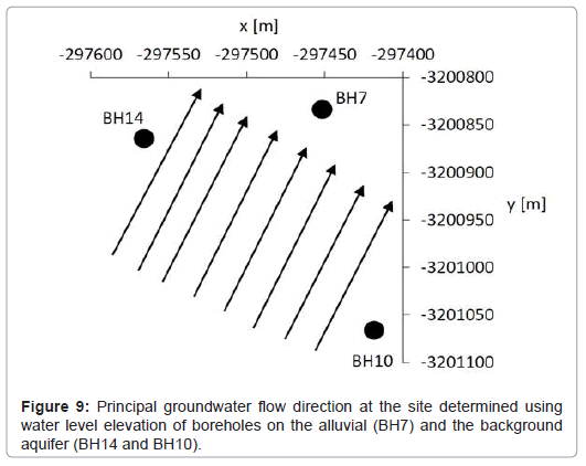
Figure 9: Principal groundwater flow direction at the site determined using water level elevation of boreholes on the alluvial (BH7) and the background aquifer (BH14 and BH10).
Geological characterization shows that the alluvial aquifer is composed of calcrete, clay-silt and gravel-sand unconsolidated sediments overlying low permeable shale bedrock. The nature and type of the unconsolidated sediments spatially varies on the site and thus potentially influencing the hydrogeological setting of the aquifer. Calcrete and shale outcrops were observed in the vicinity of the study site. A groundwater discharge zone at the contact plane between the overlying unconsolidated sediments and the shale of the underlying bedrock was also identified during outcrop mapping. Groundwater in the alluvial aquifer occurs in the alluvium-silt and gravel-sand unconsolidated sediments. The gravel-sand sediments that consist of small to large pebbles are conceptually the most yielding hydrogeologic unit of the alluvial aquifer. The study shows the potential usefulness of outcrop mapping and analysis of drilling logs in improving understanding of heterogeneous aquifer lithology and preliminary hydrogeological setting that is important for aquifer testing.