Journal of Chemical Engineering & Process Technology
Open Access
ISSN: 2157-7048
ISSN: 2157-7048
Research Article - (2019)Volume 10, Issue 1
The elbow plays a crucial role in changing the flow direction of the medium in pipeline system and is one of the most commonly used pipeline components in the oil and gas transportation. This paper focuses on the corrosive failure mechanism of the elbow of regeneration tower of LPG desulfurization unit in a refinery. Aiming at the failure elbow, based on the macro and micro perspectives, the physical laws of the inner layer of the elbow, including the distribution of corrosion holes and wall thickness, are summarized and analyzed. The further characterization methods were used to study the corrosion mechanism, including mechanical properties, metallographic examination, X-ray diffraction analysis (XRD), scanning electron microscopy (SEM) and energy spectrum analysis (EDS). Taking the thief hole as center, the elbow was divided into 4 rows. It is found that the maximum diameter was 21.1 mm while the minimum was 7.76 mm, and the vast majority of holes were 16 ~ 19 mm. The average size of the middle section was larger, meanwhile, possessed most holes over 19 mm. The corrosion thickness first increased then decreased along the flow direction and reached the maximum in completely destroyed area of the 1st and 2nd row. The corrosion thickness increased gradually along the flow direction of the 3rd and 4th row. Erosion corrosion is the main cause of elbow failure. Fluid erosion plays a dominant role in the failure process while electrochemical corrosion plays a dominant role in the formation of corrosion holes. Besides, the presence of heat-stable salts (HSS) also aggravates the corrosion of elbow.
Corrosion; Desulfurization; X-ray diffraction analysis
Liquefied petroleum gas (LPG), which is mainly produced by oil and refinery enterprises, has many applications. In chemical production, LPG can be separated into ethylene, propylene, butylene and butadiene, which are used to produce synthetic plastics, rubber, synthetic fibers and pharmaceutical, explosive and fuel products. When used as fuel, it has been widely used in people's life because of its high calorific value, smokeless dust, no carbon residue and easy operation. In addition, it is also used to cut metals, bake agricultural products and roast industrial kilns [1]. The global LPG supply and forecast data from 2015 to 2021 is listed in Table 1. As can be seen from the table, the global LPG production continues to increase, which with an annual growth rate of more than 2%, and has become an indispensable part of the energy structure in the world [2].
| Year | 2015 | 2016 | 2017 | 2018 | 2019 | 2020 | 2021 |
|---|---|---|---|---|---|---|---|
| Supply/million tons | 277 | 284 | 296 | 307 | 317 | 325 | 332 |
Table 1: 2015~2021 global LPG supply and forecast data.
LPG is a by-product of catalytic cracking and thermal cracking of crude oil, thus leading to considerable sulfides contained in oil entered into LPG with refining process. It is well known that sulfides contained in LPG will induce unqualified products and sever corrosion of pipes and equipment in subsequent production processes. And there will be considerable environmental consequences if sulfur-containing LPG is used as fuel. Beyond that, the crude oil has become progressively high-sulfidation and high-vulcanization across the globe, leading to exigent to remove sulfides contained in LPG [3].
Currently, LPG desulfurization (mainly H2S) has two kinds of dry and wet methods. Dry method is the removal of hydrogen sulfide by solid adsorption bed, which is only used to treat gases containing trace hydrogen sulfide. Activated carbon, alumina and molecular sieve are commonly used as solid adsorbents. In batch operation, most desulfurizers are non-renewable and have high investment, which greatly limits their application in industrial production. Wet method is the removal of hydrogen sulfide by liquid desulfurizer, which has the advantages of large processing capacity, continuous operation, low investment and operation cost. Therefore, the mainstream is wet method in industrial application, among which the alcohol-amine method is used more frequently than others. Alcohol-amine method, use amine as a desulfurizer, achieved desulfuration effect mainly through chemical reaction between amine and H2S. The common desulfurizing agents include monoethanolamine (MEA), diisopropanolamine (DIPA) and N-methyldiethanolamine (MDEA). Among them, MDEA is the most widely used in LPG desulfurization [4,5]. The main chemical reactions of alcohol-amine method are as follows:
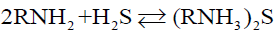 (1)
(1)
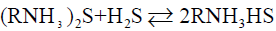 (2)
(2)
RNH2 represents alcohol amines.
Reactions (1) and (2) are both reversible exothermic reactions. Decreasing temperature and increasing pressure are favourable for the reaction to proceed to the right side, forming sulfides and acid sulfides, and absorbing H2S. Increasing temperature and reducing pressure are favourable for the reaction to proceed to the left side, and sulfides are decomposed to release H2S, which is a regeneration process of amine solution [6,7].
Plainly, absorption of H2S and regeneration of amine are realized just through the above two reactions. Besides, alcohol-amine method has been becoming a leading one due to its low energy consumption and excellent purification effect. However, it has been reported that H2S in LPG created a host of corrosion problems owing to the fact that the desulfurization equipment was mostly made of carbon steel. Corrosion problems are too damaging or too lasting will not only result in thickness decrease of the equipments, affect the normal operation of the production, and would cause leakage of material, and even bursts the grave secure mishap. Outside of these, corrosion products will lead to desulfurizer foaming and degradation, which will increase consumption of desulfurizer and energy of whole process [8].
At present, there have been a substantial amount of reports both experiment [9-14] and numerical simulation [15-19] on corrosion of elbow by hydrogen sulfide-containing medium. However, most studies only considered chemical laws, but not physical laws. Base on the macro and micro perspectives, this paper plans to explore corrosion failure mechanism of elbow from two aspects of physics (thinning rule, hole size distribution) and chemistry (XRD, EDS and so on).
Failure analysis of elbow
The elbow of the regenerator tower of the LPG desulphurization equipment in a petrochemical plant in Shanghai has been seriously leaked because of the corrosion perforation, then the leakage area was repaired, as shown in Figure 1. Four months later, the second leak appeared, physical map of elbow was shown in Figure 2, desulfurization process and failure location shown in Figure 3.

Figure 1: Welding photo of elbow.

Figure 2: Physical map of elbow.

Figure 3: Desulfurization process and failure location.
The equipment was designed to remove H2S from LPG produced by petroleum hydrocracking, the main parameters shown in Table 2. The main components of LPG and parameters of desulfurizer are listed in Table 3 and Table 4.
| Parameters | |
|---|---|
| Desulphurization method | Alcohol-amine method |
| Desulphurizer | MDEA |
| Circulation amount | 63.94 t/h |
| Material of elbow | Carbon steel |
| Working temperature | 120°C |
| Working pressure | 0.2 MPa |
| Diameter | 600 mm |
| Thickness | 10 mm |
| Repair welding thickness | 20 mm |
Table 2: Parameters of desulfurization equipment.
| Component | Methane | C2 | Propane | Butane | Pentane | H2S | Others |
|---|---|---|---|---|---|---|---|
| Volume fraction/% | 1.29 | 6.3 | 18.82 | 49.71 | 15.26 | 7.8 | 0.82 |
Table 3: Composition of LPG.
| Parameters | pH | Conductivity | MDEA concentration | HSS concentration | HSS anion concentration |
|---|---|---|---|---|---|
| Value | 9.6 | 9.2 mS/cm | 17.81% | 2.86% | 1.15% |
Table 4: Partial parameters of amine.
Macroscopic analysis
The failure elbow was cut along the central axis and divided into two parts. No obvious corrosion features were observed on the inner elbow while the other side was heavily corroded. The physical map of outer elbow is shown in Figure 4. It can be seen that the whole inner wall was black and yellow brown, and all had varying degrees of corrosion, especially in the middle and near the flange. What’s more, the surface roughness was high, there still remained a little corrosion product in part area. The elbow surface presented cribriform architecture, which is full of uneven size, regular shape and honeycomb pitting. Due to long-term corrosion, many pits have been in conjunction with each other which formed large-scale destruction area.

Figure 4: Physical map of outer elbow.
Figure 5 was the scour appearance of complete destruction area near the exit, and the trace of the fluid scour can be clearly seen from it. The scour path in figures presented orientation, which coincided with flow direction. Figure 6 was the scour morphology near corrosion holes. It was obvious that the thickness of edge region was much smaller than that of center, and there exist typical thinned lip structures which were caused by fluid erosion. Therefore, it can be concluded that the erosion-corrosion was a vital factor that resulted in the failure of elbow.

Figure 5: Scour pattern near the outlet.

Figure 6: Scour pattern near holes.
Corrosion hole analysis: The corrosion morphology of the elbow was typical honeycomb appearance which composed of standardized and different size holes. The size of holes was measured and analyzed for mastering distribution law of corrosion holes and deeply studying failure mechanism of the elbow. Taking the thief hole as center, the wall was divided into 4 sections, and the distance was taken as 15 cm, 10 cm, 10 cm and 15 cm, respectively. The physical drawings and schematic diagrams are shown in Figures 7 and 8.

Figure 7: Physical map of regional division.

Figure 8: Sketch map of regional division.
After on-site measurement and analysis, a total of 103 holes were sorted out by regions. It is found that the maximum diameter was 21.1 mm while the minimum was 7.76 mm, partial results shown in Figure 9, and the vast majority of holes were 16 ~ 19 mm. The average size of the middle section was larger, meanwhile, possessed most holes over 19 mm. This showed that when diameter reached or exceeded 21.1 mm, the area around the holes may gradually developed into a complete failure region.

Figure 9: Hole size distribution.
To further discuss the distribution of the holes, drawings were made with diameter as ordinate and distance as abscissas, as shown in Figure 10. The dashed area represented complete failure region where corrosion was the worst. It can be easily noticed that the diameter was approximately trapezoid along flow direction. From the inlet of the elbow, the hole size had a tendency to increase continuously, then later had a large area of complete destruction in the middle of elbow (the area of 20~70 cm from the exit), and then had a decreasing trend. Areas division of elbow is shown in Figure 8. The hole size of the area ① and ③ ④ decreased along with the flow direction until disappeared completely, while there was a small area of complete destruction of area ② in exporting nearby. There may be two reasons for this phenomenon. One possibility was the area near flange, and there will generate far more resistance when fluid passed through, as shown in Figure 11. The second was the area existed legions of gaps caused by corrosion, which may resulted in fluid accumulation and graver corrosion. The radial direction analysis showed that the diameter distribution accorded with the normal distribution. At equidistance, the diameter of the edge area was smaller while the middle was relatively larger.

Figure 10: Hole distribution.

Figure 11: Corrosion morphology in exporting nearby.
Analysis of thinning law: Regional sampling of the inner wall was carried out to obtained corrosion thinning laws of the elbow; the initial scheme was shown in Figure 8. Taking the thief hole as center, the wall was divided into 5 rows, numbered 1~5 from top to bottom. The interval of each row of adjacent samples was 15 cm, numbered 1~8 from left to right. However, samples cannot be removed completely since the edge area was too thick in actual sampling process. Therefore, the following adjustments were made: the 1st row was abandoned, the 2nd and 5th row were moved 5 cm upwards, and 5~6 samples are taken in each row, and the rest remained unchanged, as shown in Figure 12. Firstly, the inner wall removed completely using cutting machine. Then, subsequent sampling process was performed using a chainsaw; plasma cutting and hand saw to ensure physical and chemical properties of samples stably. As shown in Figure 13, the physical map of 3-2~3-5 showed that there was a significant difference in thickness between samples. Each sample was measured 4 times from different angles and averaged, as shown in Figure 14. The 1st and 2nd rows passed through complete failure zone, for the integrity of the image, the thickness of these area was 0, and corrosion thickness was 10 mm.

Figure 12: Sketch map of sampling.

Figure 13: Samples.

Figure 14: Thickness distribution.
Obviously, there was an identical rule between the 1st and 2nd row of thinning laws. The thickness was equal to initial thickness of the pipe near the inlet, that was, there was no palpable corrosion behaviour in this area. Along the flow direction, corrosion thickness gradually intensified, and then reached the maximum in completely destroyed area. Subsequently, corrosion thickness showed decreasing trend, and then slightly increased. The 3rd and 4th row have not passed through complete destruction area and therefore the corrosion thickness was successive, that was, it increased gradually along the flow direction. The maximum corrosion thickness of the 3rd and 4th row both were near of the export, and both were 5.5 mm.
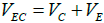
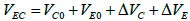
We have concluded that erosion-corrosion was a vital factor during the failure process of elbow from Figures 5 and 6. Actually, erosioncorrosion is composed of four components, pure corrosion, pure erosion, erosion–enhanced corrosion and corrosion–enhanced erosion can be expressed as follows [19]:
 (3)
(3)
 (4)
(4)
where VEC is the total erosion-corrosion rate; VC is the total corrosion rate determined by hydrogen sulfide; VE is the total erosion rate determined by fluid scour; VC0 is the pure corrosion rate; VE0 is the pure erosion rate; △VC is the erosion–enhanced corrosion rate; △VE is the corrosion–enhanced erosion rate.
According to the fact that there is no obvious corrosion phenomenon in the inner elbow, it can be inferred that VE plays a dominant role in the failure process of elbow, VC0 is relatively slow, and the appearance of corrosion holes is mainly due to △VC. Comprehensive considering distribution of holes and thinning laws, we can assume that hole size and corrosion thickness in the middle area (area ② and area ③) are significantly larger than those in the surrounding area, which indicates that VE and VC in the middle area are larger.
The size and density of corrosion holes reflect the value of VC. Combining with Figures 9 and 10, VC in the middle area of elbow (area②and area③) can be obtained, that is, the total rate of VC0 and △VC is significantly higher than that in the surrounding area. Therefore, Figure 10 not only reflects the distribution of corrosion holes, but also represents the distribution of △VC in elbow. Figure 14 not only reflects the distribution of wall thickness, but also represents the distribution of VE.
Microcosmic analysis
Analysis of material and mechanical properties: Since the failure and leakage of elbows are caused by perforation, in order to eliminate the possible quality problems of pipelines, the material composition of elbows is analyzed. The analysis results are shown in Table 5. Comparing the analysis results with the requirements of the national standard, it is found that the content of C element in elbow is slightly higher, and the content of other elements meets the requirements of the national standard.
| Parameters | C | Mn | Si | S | P | Cr | Ni | Mo | Cu |
|---|---|---|---|---|---|---|---|---|---|
| Measured value | 0.21 | 0.66 | 0.28 | 0.011 | 0.014 | 0.072 | 0.045 | 0.005 | 0.009 |
| National standard | = 0.22 | = 1.40 | = 0.35 | = 0.050 | = 0.045 | / | / | / | / |
Table 5: Analysis of material components of failure elbow.
After sampling near the elbow failure location, the mechanical properties are tested. The results are shown the Table 6. According to the data in the table, the test results of the bending strength, tensile strength and elongation after breaking of the sample are all normal, and the mechanical properties of the elbow are normal.
| Parameters | Lower yield strength /MPa | Tensile strength /MPa | Elongation after breaking |
|---|---|---|---|
| Measured value | 309 | 494 | 26 |
| National standard | = 235 | = 370 | = 20 |
Table 6: Results of mechanical properties of failure elbow.
Metallographic examination: In order to determine whether the metallographic structure of the failure elbow is normal, the metallographic examination of the elbow was carried out after simple treatment of the sample. The results show that the metallographic structure of the samples is mainly ferrite and pearlite, and the grain size of ferrite is 10 grades, as shown in Figure 15. The results showed that the metallographic structure of the site was normal.

Figure 15: Metallographic structure of failure elbow.
XRD analysis: The composition of corrosion products can be obtained through XRD analysis, which is helpful to further analysis the failure mechanism of elbow. In order to make an accurate and comprehensive analysis, 4 samples are selected in each row. After searched and matched, it was found that the main phases were FeS2 and Fe, and partial samples contained a small amount of FeS, as shown in Figure 16.

Figure 16: XRD images of samples.
SEM-EDS analysis: The combination of SEM and EDS analysis can not only provide micromorphology of the samples, but also make qualitative and semi quantitative analysis of components. The SEM results of 2-2 are shown in Figures 17 and 18. As can be seen from the diagram (a), the surface of the sample is uneven and has many defects. With the increase of magnification, it can be observed that the surface is relatively rough, besides, the inner structure is loose and riddled with gullies and crevices. When magnification reach to 10000, the flake-shaped and massive corrosion products that remain in the surface and gaps can be clearly seen, which indicated that the strength of bonding force between corrosion product and matrix was so insufficient that cannot protect the matrix.

Figure 17: SEM images of samples.

Figure 18: EDS images of samples.
Corrosion mechanism analysis
MDEA is a tertiary amine that is less basicity and therefore less corrosive to equipment. According to experimental study [20], corrosion rate of carbon steel by pure MDEA is less than 0.04 mm/a, which is negligible compared with actual corrosion rate of elbow. Combined with the foregoing analysis, it can conclude that main corrosion causes are electrochemical corrosion caused by H2S, erosion-corrosion and HSS corrosion.
Electrochemical process of metal corrosion in wet H2S environment: According to real-time measurement data provided by petrochemical plant, the content of H2S in the feed gas is 7.8%, therefore it can be inferred that H2S corrosion is a significant factor in the corrosion process. As we all known, dry H2S has no corrosive effect on metals, but strong corrosivity in wet environment. It will ionize gradually and acerbic when dissolved in water [21-23]:
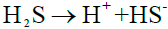 (5)
(5)
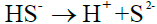 (6)
(6)
The subsequent electrochemical process:
Anodic reaction: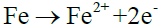 (7)
(7)
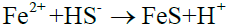 (8)
(8)
or  (9)
(9)
Cathodic reaction: (10)
(10)
Total reaction: (11)
(11)
The H+ released by hydrolysis of H2S is a strong depolarizer, which can easily capture electrons at cathode, promoting anode dissolution reaction and leading to corrosion of the wall. The binding force between anode reaction product and matrix is weak, therefore it is prone to exfoliation phenomenon1. Whereafter, the wall is exposed, which makes the corrosion reaction intenser and circulate constantly.
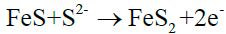
The result of XRD shows that only a small amount of FeS exist in corrosion product, and mostly is FeS2. A further analysis of corrosion combination with the literature indicates there exist following reactions [24-28]:
 (12)
(12)
 (13)
(13)
With FeS generated by electrochemical reaction, the product is increasing and then forming protective film, covering the wall surface. However, there are more S2- and HS- in the nearby fluid, so it is vulnerable to generate FeS2, as shown in reaction (12) and (13).
Erosion-corrosion: The erosion-corrosion is a metal damage phenomenon between metal surface and corrosive fluid caused by high-speed relative motion. The whole process is relatively complex, temperature, pressure, flow rate, fluid distribution, surface microstructure and other factors all will affect corrosion rate. Due to the high concentration of H2S in LPG, there will undergo chemical reactions of H2S and carbon steel which can generate a protective coating which will prevent contact between the wall and corrosive medium.
• Based on the Newton's law of viscosity, the fluid will produce a large shear stress on the metal surface under high velocity. The SEM results showed that the corrosion product film was loose, porous, and cannot tightly integrated with substrate, thus it will damaged readily and taken away from metal surface. The higher the flow rate, the greater the scour force, the faster the protective film will fall off [29-32]. When corrosion product film appears to fall off, the metal matrix will be exposed, then there will be a small anode and large cathode galvanic corrosion in the area where without and with corrosion product film, and finally induce the pitting corrosion occurred at the region without corrosion product film. The formation and growth of pit will result in a typical honeycomb shaped corrosion morphology with continuous development of corrosion [33,34].
• Compared with straight pipe, elbow has structure specificity which makes the velocity, flow direction, and fluid distribution all mutated. Moreover, the large curvature of elbow is very susceptible to boundary layer separation phenomenon which will creates an abundance of vortices that cause mechanical energy consumption, and then enhance turbulent flow in pipes, and thereby accelerate corrosion of elbow [18,19].
HSS corrosion
The salts generated by the reaction of amine react with H2S can be decomposed after heating, and then amine can be regenerated, as shown in reaction (1) and (2). However, the salts formed by the reaction of some anions with alcohol amine do not decompose under the condition of amine regeneration, so they are collectively referred to as HSS. The common anions include Cl-, SO42-, C2O42- and so on.
According to the data provided by the petrochemical plant, the content of HSS under actual working conditions was 2.86%, which was obviously higher than 0.5% that recommended by P.C. Rooney [35]. When the content of HSS exceeds the standard, it is easy to cause foaming of amine, which reduces the total amount of amines that can absorb H2S. This will not only reduce purification efficiency and processing capacity of the system, but also affect the normal operation of the device, and lower LPG quality. On the other hand, various kinds of HSS can easily replace the S2- on FeS, thereby destroying the formed corrosion product protection film, making corrosion more serious at elbow. In addition, the presence of HSS will promote the electrochemical reaction of primary batteries. The higher the HSS concentration, the more obvious the promotion effect is [36].
• The macroscopic observation, diameter analysis, XRD and SEM-EDS testing of the failure elbow are carried out. And the corrosion mechanism is studied in a comprehensive method.
• The corrosion morphology of the elbow was typical honeycomb appearance which was composed of different size and standardized holes. After measuring the hole size and wall thickness, it is found that the hole size is trapezoid and the wall thickness is gradually thinning along the flow direction.
• Fluid erosion plays a dominant role in the failure process while electrochemical corrosion plays a dominant role in the formation of corrosion holes. The main corrosion causes are erosion-corrosion and electrochemical corrosion caused by H2S, and HSS corrosion, and they promote and develop mutually and ultimately lead to elbow corrosion failure.
Through the whole research process, it is not difficult to find that H2S plays an important role in the whole elbow failure process, so if the content of H2S in the feed can be reduced, the erosion-corrosion rate will be significantly reduced. The results of CFD simulation show that the porous morphology will affect the erosion-corrosion rate and the gas film formed on its surface will slow down the corrosion rate of the second layer steel plate. So the factory can use porous plate to replace ordinary steel plate.
As for the corrosion mechanism of failure elbow, CFD simulation and experimental research will be carried out in the future. Through CFD simulation, the corrosion distribution of elbows, the effect of porous media on corrosion and the method of reducing corrosion rate were studied. Through experimental research, the effects of temperature, pressure, treatment capacity and other factors on corrosion were studied.
The authors acknowledge the financial support of the National Key Technology R&D Program of China (No. 2015BAK39B02).
Citation: Jianwen Z, Guoqing S, Chuansheng W (2019) Corrosion Failure Analysis of Elbow in LPG Desulfurization Unit. J Chem Eng Process Technol 10: 395. doi: 10.35248/2157-7048.19.10.395
Received: 24-Apr-2019 Accepted: 30-Apr-2019 Published: 09-May-2019 , DOI: 10.35248/2157-7048.19.10.395
Copyright: © 2019 Jianwen Z, et al. This is an open-access article distributed under the terms of the Creative Commons Attribution License, which permits unrestricted use, distribution, and reproduction in any medium, provided the original author and source are credited.