Journal of Aeronautics & Aerospace Engineering
Open Access
ISSN: 2168-9792
ISSN: 2168-9792
Research Article - (2021)Volume 10, Issue 9
Aircraft icing and ice accretion pose great threat to the safety as the accumulated ice affects the aerodynamic profile of the airfoil hence extensive investigation is being done to understand ice accretion on airfoils. These studies help us understand how lift, drag, pressure and the velocity control is affected due to accumulated ice and how certain measures can be taken to ensure an efficient flight while minimizing risks posed to the safety. This paper focuses on the differences in the aerodynamic parameters on different NACA profiles and how each airfoil is affected by the ice accretion. The computational analysis of this research concentrates on the performance parameters of airfoils of NACA four, NACA five and NACA six digit series on conditions with clear ice, rime ice and without ice for different values of angle of attack. The key research objective of the paper was to investigate how each airfoil is affected under the different icing conditions and compare the results to study ice accretion on different airfoils, namely, NACA0012, NACA23012 and NACA643218. The 2D model of the airfoils was developed with Solid works and Standard K-€ model was used for CFD analysis.
Aircraft icing; Ice accretion; Airfoil; CFD analysis
The natural phenomenon of ice formation in the atmosphere requires very cold temperature or ice nuclei which can initiate the process of freezing natural materials such as dust, bacteria, plant material or other substances that mimic the ice-structures used by the liquid cloud droplets as catalysts for the formation of ice. In the absence of ice nuclei, the water is suspended as super-cooled droplets (diameter exceeding 50 μm) even at temperatures lower than 0°C. An aircraft, therefore, functions as a giant flying ice nucleus and the structural icing occurs when super-cooled droplets come in contact with the surface at temperatures near or below 2°C. Aircraft icing is the event where large droplets of super-cooled liquid accumulate onto the surface of the airplane (at temperatures closer to 0°C) as it passes through moisture laden clouds or freezing rain or freezing drizzle (at temperatures below 0°C). The accumulated ice causes undesirable effects on the aerodynamic characteristics of the aircraft as it changes the airfoil shape which results in the aircraft to stall at a notably higher airspeed. Icing also decreases the amount of lift that an airfoil produces while increasing drag. It may block or limit the control surfaces thereby making the control inputs less effective posing a threat to the safety. Larger droplets of water suspended in the air have a higher chance of impingement on the aircraft as it has more inertia therefore less affected by the airflow as compared to smaller droplets. The greater the concentration of moisture in the cloud, the greater will be the chances of ice accretion. Thin wings have a higher chance of the droplets striking the wing surface. The number of droplets striking the aircraft in a certain time increases with increase in aircraft speed. For ice accretion to occur, the outside temperature must be equal to or lower than the freezing temperature. When an aircraft flies through a cloud containing high concentration of large super cooled water droplets at a temperature of 2-10°C which freezes (part of it)on impact, a solid clear sheet of ice that adheres firmly on surface is formed, called clear or glaze ice. At temperatures between 0°C and -15°C, the droplets are large and numerous and results in the dangerous accumulation of clear ice. Rime Ice: When clouds are formed in stable air at freezing temperature and composed of relatively small number of tiny water droplets at temperatures below -15°C, rime ice formation takes place. At temperatures between -15°C and -20°C where smaller, less numerous water droplets strikes the aircraft surface, which is below freezing temperature, the droplets freezes completely before another freezes on top of it. This results in the ice accumulating in tiny pellets, frozen together in a spongy mass which is opaque or milky white and forms a sharp protruding ridge which does not affect the airflow as much as clear ice does.
Problem research gap analysis
From the review of existing literature, it is evident that numerous studies have been done on icing of aircrafts and how it affects the aerodynamic parameters and the measures taken to prevent or reduce aircraft icing. The method involves simulating the clear ice and rime ice formation on the airfoils to study the effects of such icing on the aerodynamic characteristic and how airfoils of different NACA series are affected by the ice formation. This study compares the aerodynamic performance of four digit series NACA0012, five digit series NACA23012 and six digit series NACA 643218 airfoil in order to conclude which airfoil had the best performance with minimal loss of aerodynamic efficiency that could be operated in conditions of icing. The results of this study will contribute to further advance and broaden the knowledge on aircraft icing and its effect on the aerodynamic parameters and how different airfoil shapes are affected by icing.
Purpose
The purpose of this study was to examine the flow over the airfoils of different series of airfoils with and without ice accretion for a fixed altitude has been examined. Performance of airfoil series such as NACA0012 which is a symmetrical airfoil with no camber, NACA23012 most effective five-digit series of NACA 5 series and NACA643218 of six-digit NACA series, without any ice accretion and with two types of ice accretions, Clear ice and Rime ice which effects the performance of aircraft is studied. Ice accretion on the leading edge over the surface is designed and analyzed in Computational Fluid Dynamics, Fluent Analysis and with MATLAB. Leading edge of airfoil is rotated at an Angle of Attack (AOA) of 4° as we get maximum Lift at this angle of Attack. Corresponding to the leading-edge angle of attack the velocity of the flow is maintained at 250 m/s which is 0.8 Mach number and the flow considered is subsonic. The ice accretion is designed on the leading edge of the airfoil. Parameters such as pressure, temperature, density, viscosity are taken from the International Standard Atmosphere charts corresponding to the altitude.
Review of existing literature
The effect of icing on the aerodynamic parameters of an airfoil and how different airfoils are affected by the ice accretion which is a major safety threat is investigated extensively in the field of aviation. Few papers addressing the ice accretion on aircrafts is reviewed below. Beaugendre H et al. [1] discusses the two-dimensional and quasi-three-dimensional in-flight ice accretion simulation codes which have been progressively applied by the aerospace industry in the last two decades in assistance to the certification process. These codes forecast two dimensional sectional ice structures, which are then fabricated from a light material and fixed as replaceable hurdles on test aircraft to examine them for stability under icing experiences. Though effective for computing ice structures on simple geometries, present codes experience significant issues or just can’t simulate ice structures on truly three-dimensional geometries such as non-axisymmetric nacelles, high-lift wings, engine intakes, or systems that integrate external and internal flows. As a comprehensive icing system for in-flight ice simulation in both two and three dimensions, FENSAP-ICE and any Euler or Navier- Stokes’s code is used to calculate the air flow where DROP3D uses the considered air flow to determine droplet impingement minus particle tracking. ICE3D is used to determine the effect of the ice shape on affected surfaces with the help of the shear stress and convective heat fluxes from the FENSAP solution and the water catch from DROP3D. FENSAP-ICE is found to effectively estimate the collection effectiveness on both two-dimensional and threedimensional bodies. Development of anti-icing ability will be done inside the ice accretion module.
In this paper, a simple process was displayed to change the stability and control limits of aircraft to imitate the result of accumulation of ice [2]. To investigate the outcome of ice accumulation on the dynamics of aircraft which includes the turbulence and sensor noise, a six degree-of-freedom computational flight dynamics model was applied. The main objective of this paper was to establish methods to recognize the result of ice accretion on the functioning and control of aircraft during quasi-steady-state flight. The technique is applied to analyze a method for noticing the accumulation of ice through the change in steady-state aircraft parameters. To present a simple model to understand limited iced aircraft flight data with the use of ice is found to perform well. The turbulence in the atmosphere and sensor noise produces scatter in the sensor data which can be effectively processed. Flight maneuvers, like holding turn, elevate the results of ice and thus enhance the ability for sensing.
Prasad G, et al. [3] here, to assess the impact of different ice shapes about airfoils, ice accretion tests are carried out in a low-speed subsonic wind tunnel testing facility and also through numerical simulation. For the comprehensive experimental analysis, ice profiles soaked using balsa wood with glace, horn and mixed ice accretion cases. To evaluate the effect of different ice shapes on the aerodynamic coefficients (Cl and Cd), computational fluid dynamics analysis is performed when ice is accumulated at leading edge of the airfoil. Cl and Cd were found to have changed instantly more than 40% in comparison to the clean wing design. Similarly, the skin friction coefficient also changes suddenly for varying ice shapes that have the ability to cause flutter at the critical speed of the airplane. The numerical simulations signal that the glaze, horn and mixed icing occurrence produce exceptional effects on the aerodynamic coefficients due to the development of separation bubbles about the leading edge. Even at low velocity, the stalling angle and the maximum Cl decrease by 10 and 50%. Therefore, it is found that the spanwise and chordwise mound of ice buildup is very risky for an airplane at various flight missions. These further effects the sound operation of anti-icing systems positioned on the leading edge of an airplane wing. Thus, to fulfil the FAR for icing conditions the lack of ice accumulation must be guaranteed following the de-icing systems without any spanwise ice ridges.
In this paper, icing simulations concerning super-cooled large droplets (SLDs) on a NACA0012 airfoil and a commercial axial fan were conducted taking into account the distinctive behavior of SLD icing (i.e., splash-bounce, deformation, and breakup). The simulations were executed considering weak coupling between the flow field and droplet motion. The flow field was computed with the Eulerian method, where the droplet motion was simulated through the Lagrangian method. An extended Messinger model was applied for thermodynamic computation to depict the ice shape. The icing simulation outcome for the axial fan, in regard to the spread of ice on the blade and the effect it had on the flow field, suggested that flow separation took place and the mass flow rate of the flow passage declined. The splash and bounce occurrence significantly affected the icing process but the outcome of the deformation and breakup phenomena was very small. With drop in the SLD temperature (from -5°C to -15°C), the number of bonding SLDs was more, while the number of splashing and bouncing SLDs dropped. Icing simulations were conducted taking into account splash, bounce, deformation, and breakup. The results of the SLD simulation for NACA0012 were aligned with the experimental data regarding the ice shape. In the SLD icing simulation of the axial fan, when the SLD-specific effects were considered, the collection was found to be dispersed at the region close to the hub and the tip on the pressure side. The SLD icing influenced the flow field around the fan blade, and flow separation was detected after the icing layer. The ice thickness about the leading edge when the SLD-phenomena were taken into account was smaller than when it was not, and the ice thickness was observed to increase towards the trailing edge. The number of droplets sticking on the blade was higher as droplet temperature fell which lead to a fall in the number of droplets that splashed and bounced [4].
Tests were directed in the Icing Research Passage (IRT) at the NASA Lewis Research Centre to archive the repeatability of the ice shape over the scope of temperatures shifting from - 15°F to 28°FEstimations of drag increment because of the ice growth were likewise made. The ice shape and drag coefficient information, with shifting complete temperatures at two unique velocities, were contrasted and the computational forecasts. In the course of recent years, the Icing Research Passage (IRT) at the NASA Lewis Research Centre has gone through a few restorations which have improved its capacities in mimicking genuine icing conditions. A portion of the upgrades incorporate another furthermore, more impressive fan engine, another shower bar framework, another computerized control framework, and different upgrades to the IRT structure. Accordingly, the IRT would now be able to give more exact control of the velocity and temperature, more uniform mists covering a bigger cross-segment of the test segment, furthermore, lower fluid water content [5].
The impingement conduct of huge water drops; their associations with the strong divider and the ensuing ice accumulation and streamlined impacts have become a major question in inflight airplane icing. In this examination, ice accumulation and streamlined consequences for a multi-component aerofoil were examined under the as of late presented Addendum O icing envelope. Supercooled large drop (SLD) elements were considered by utilizing a brought together computational methodology. Ice growth was reproduced utilizing an incomplete differential condition (PDE) based solver, rather than the generally utilized control volume strategy [6].
In the trip of planes ice growths can be found on the wing surface on account of the impingement of super cooled drops. Consequently, the planned streamlined state of the wing surface will be changed by the ice growths with the end goal that the streamlined presentation debases and the flight security can be perniciously influenced. All in all, ice gradual addition is explored by three methods: experiments, designing techniques and mathematical reproduction. Designing techniques utilize experimental formulae and delegate trial information to explore the ice accumulations, implying that the interaction of the ice growth is hard to examine. Because of these obstacles, mathematical re-enactment is generally used to foresee ice growth [7].
In the current article, the issue of in-flight ice aggregation on multi-component aerofoils is considered mathematically. The subsequent advance is the count of bead directions and drop assortment efficiencies. In the following stage, convective warmth move coefficient disseminations around the aerofoil components are determined utilizing the Fundamental Limit Layer Technique. Ice amassing on pieces of the airframe is one of the key issues of flying. Ice development on wings, tail surfaces, fuselage and different things like the motor admissions and pitot tubes bring about extreme execution degradation, in this way undermining flight security. For instance, alteration of the wing shape because of amassed ice brings about diminished lift along with expanded drag and weight [8].
The expectation of Ice shapes and the assurance of their impact on lifting surfaces is an issue of focal significance in airplane plan since Ice accumulation can antagonistically influence streamlined execution of airplane segments. As of late, research has been embraced to improve understanding of the development of the Ice, its accumulation and the ramifications for streamlined execution. Reference l gives an outline of the logical and trial icing activities in progress and reference a survey of the advancement on one component of the general movement, to be specific the unprotected aerofoil icing issue [9].
The point of this paper is to introduce the Italian icing computational climate code, I CE, created by CIRA, and examine its assessment for ice growth on single and multielement aerofoils. The streamlined module of the code depends on a potential board technique, while the thermodynamic module is based on the exemplary Massinger model. Various approaches to settle the timesubordinate ice gradual addition issue have been considered. An examination between hypothetical estimations utilizing multi-timestep, single-time-step, or indicator – corrector methodology and test information has been done. The impact of the owed consistency on bead directions and the various methodologies for the convective warmth trade coefficient count have been thought the influence on the impingement of the genuine drop size circulation has been considered and an examination with a standard middle volumetric width computation is introduced [10].
In this methodology ice accretion on three different air foils of NACA 4 digit, NACA 5 digit and NACA six digit series will be discussed at different angles of attack. In order to perform a parametric study of effect of ice accretion on the aerodynamic parameters of airfoils such as loss of lift, increase in drag and loss of control, an investigation on NACA 0012 airfoil, NACA 23012 airfoil and NACA 643218 airfoil without any ice build-up were introduced. The airfoils’ aerodynamic properties without any ice formation are used as initial test to understand how different form of ice build-up affects performance of these airfoils.
Model
Design co-ordinates have been imported from airfoil tools for the required NACA Series and the airfoil is created by joining the edges in ANSYS. A 2-D Design with Angle of Attack 4 degree is made which is extruded to make it 3D (Figures 1-3).
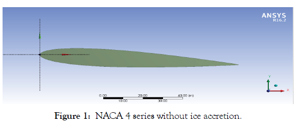
Figure 1: NACA 4 series without ice accretion.
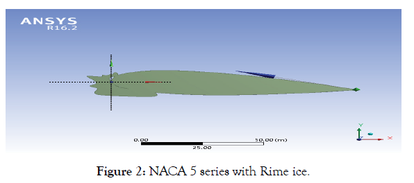
Figure 2: NACA 5 series with Rime ice.
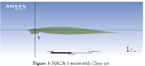
Figure 3: NACA 6 series with Clear ice.
Mesh generation
The modified airfoil design is meshed using coarse wise mesh. Refinement has been done at the edges of the airfoils (Figure 4). Inflation with respect to domain has been created for hexagonal type of meshes. For discretization of the computational domain, the Rectangular shape fluid domain is used for mesh generation. The unstructured mesh is created with all triangles method (Figures 5-7). The meshed model contains inlet, walls, airfoil, and outlet. On the airfoil, the edge sizing of 300 number of division is given and mesh refinement is 2. The grids around the areas of airfoil are made fine whereas coarse far away from it. It has 44136 nodes and 86337 elements. Mesh elements: - It has 44136 nodes and 86337 elements (Table 1).
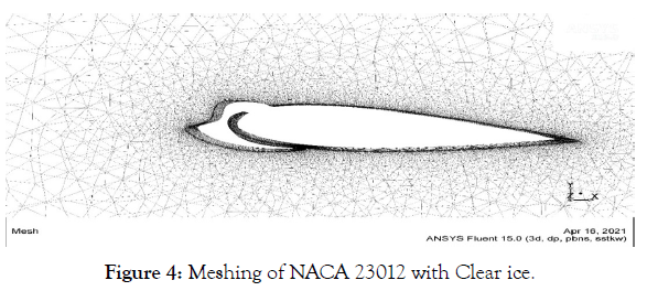
Figure 4: Meshing of NACA 23012 with Clear ice.
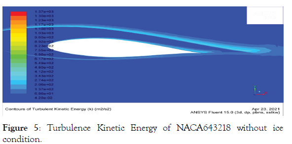
Figure 5:Turbulence Kinetic Energy of NACA643218 without ice condition.
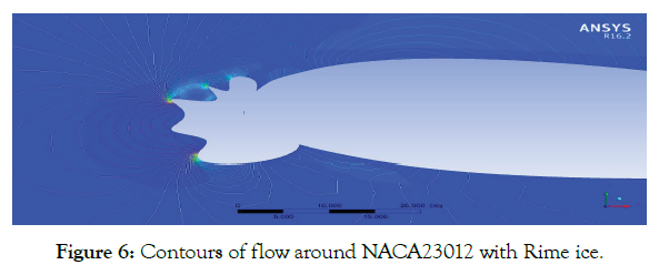
Figure 6: Contours of flow around NACA23012 with Rime ice.
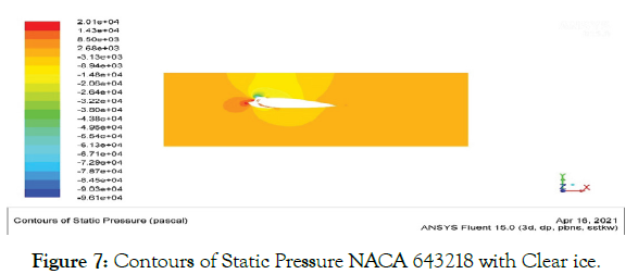
Figure 7:Contours of Static Pressure NACA 643218 with Clear ice.
| PARAMETERS | VALUES |
|---|---|
| Velocity | 250m/s |
| Angle of Attack(AOA) | 4 ̊ |
| Mach Number | 0.8 |
| Altitude | 35,000ft |
| Density | 0.7382 |
| Static Pressure | 69.710Kpa |
| Dynamic Pressure | 28.296Kpa |
| Total Pressure | 102.315Kpa |
| Static Temperature | -36 ̊ (or) 237k |
| Total Temperature | 300k |
| Specific heat Capacity at Constant pressure Cp (KJ/KgK) | 1.0038 |
| Specific heat Capacity at Constant Volume Cv(KJ/KgK) | 0.7167 |
| Dynamic Viscosity (μ) | 1.725 * 105 kg/ms (or) 1.6375e-5N-s/m^2 |
| Kinematic Viscosity (ѵ) | 1.8107e-5 m^2/s |
| Reynolds Number | 1380837 |
| Speed of sound | 638kt (or) 328.331m/s |
Table 1: Input and boundary condition for flow analysis.
The graph shows the variation of Lift Coefficient Versus Angle of Attack for symmetrical NACA0012 with and without ice accretion (Figure 8). The analysis resulted that the effect of ice accretion is more on lift coefficient as it causes decrement in lift coefficient abnormally. The stalling characteristics are also affected with ice accretion. The effect of clear ice is more on the airfoil compared to rough irregular rime ice. The stalling of airfoil without ice accretion occurs at 13 ̊ while the stalling occurs at around 9 ̊ and 8 ̊ with rime ice and clear ice respectively.
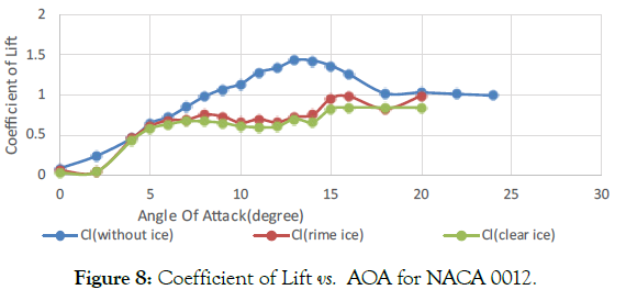
Figure 8: Coefficient of Lift vs. AOA for NACA 0012.
The graph shows the variation of Drag Coefficient Versus Angle of Attack for symmetrical NACA0012 with and without ice accretion (Figure 9). The analysis resulted that the effect of ice accumulation leads to an increment in drag which affects the flow parameters and the stability of the aircraft. The effect of ice accretion with clear ice, is more compared to rough irregular rime ice. From the graph, the drag increment due to clean ice formation is much higher over NACA0012 than rime ice on the same airfoil. The weight of the airfoil also increases which affects the stability of the entire aircraft.
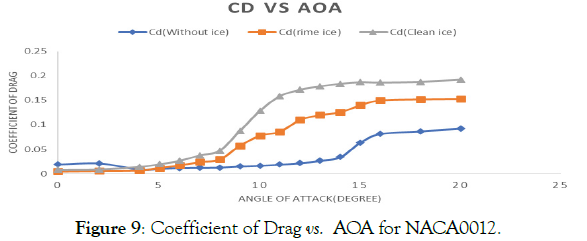
Figure 9: Coefficient of Drag vs. AOA for NACA0012.
The graph shows the variation of Lift Coefficient Versus Angle of Attack for NACA23012 with and without ice accretion (Figure 10). The analysis revealed that the ice accretion affected the lift coefficient more due to the formation of ice over the airfoil body which causes the decrement in lift coefficient abnormally. The stalling characteristics also get affected with ice accretion. The effect of clear ice is more on the airfoil compared to rough irregular rime ice. The stalling of airfoil without ice accretion occurs at 16 ° whereas the accumulation of Rime ice and Clear ice causes the aircraft to stall at 10 ° and 9 ° respectively.
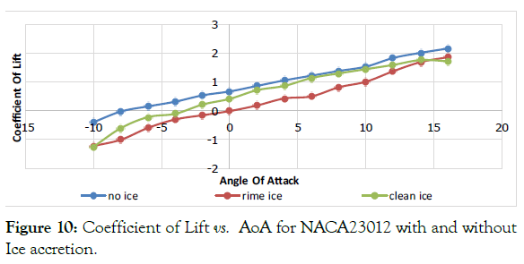
Figure 10:Coefficient of Lift vs. AoA for NACA23012 with and without Ice accretion.
The graph shows the variation of drag coefficient versus angle of attack for NACA23012 with and without ice accretion (Figure 11). The analysis resulted that the effect of ice accretion leads to greater increment in drag. Due to the increment in drag, the flow parameters and the stability of the aircraft is affected. The stalling characteristics also get affected with ice accretion. Clear ice affects the airfoil more than rime ice.
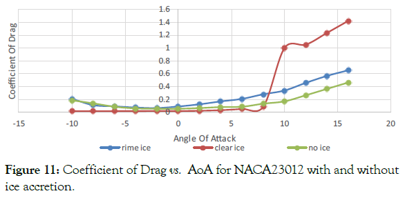
Figure 11:Coefficient of Drag vs. AoA for NACA23012 with and without ice accretion.
The graph shows the variation of Lift Coefficient Versus Angle of Attack for NACA643218 with and without the accumulation of ice (Figure 12). From the analysis, it is found that the effect of ice accretion is more on lift coefficient as it causes the decrement in lift coefficient abnormally. The stalling characteristics are also affected with ice accretion. The effect of clear ice is more on the airfoil compared to rough irregular rime ice. The stalling of airfoil occurs at 18° without ice accretion while the stalling begins at 12° and 6° when the aircraft has accumulation of rime ice and clear ice respectively.
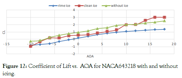
Figure 12: Coefficient of Lift vs. AOA for NACA643218 with and without icing.
The graph shows the variation of Drag Coefficient Versus Angle of Attack for NACA643218 with and without ice accretion (Figure 13). The analysis resulted that the effect of ice accretion leads to greater increment in drag. Due to the increment in drag, the flow parameters and the stability of the aircraft is affected. The stalling characteristics also get affected with ice accretion. The effect of clear ice is more on the airfoil than that of rime ice.
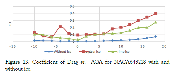
Figure 13:Coefficient of Drag vs. AOA for NACA643218 with and without ice.
Comparison of NACA series with and without ice accretion
The above graphical analysis after CFD results gives the Lift Coefficient Variation vs. AOA of three choosen NACA series i.e., NACA0012, NACA23012 and NACA643218 named as 4 series, 5 series and 6 series respectively (Figure 14). It is shown that the 6 series has maximum lift coefficient and stalling characteristics compared to the 5 series and 4 series. The stalling occurs at 18̊ for 6 series whereas at 16° and 14° for 5 series and 4series respectively.
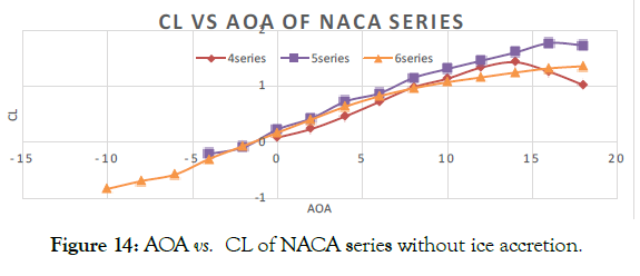
Figure 14: AOA vs. CL of NACA series without ice accretion.
The above graphical analysis after CFD results gives the Lift Coefficient Variation vs. AOA when there is accretion of rough, irregular ice called Rime ice on the three chosen NACA series for analysis i.e., NACA0012, NACA23012 and NACA643218 named as 4 series, 5 series and 6 series respectively. It is shown that rime ice results in lift decrement more on NACA 6 series than on the 5 series and 4 series (Figure 15).
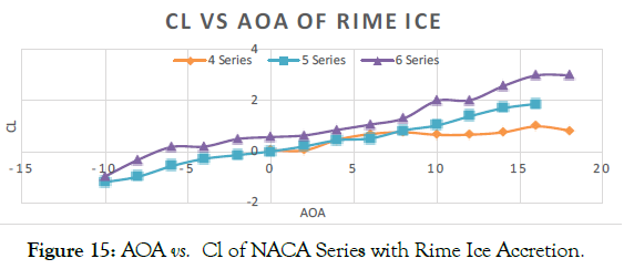
Figure 15: AOA vs. Cl of NACA Series with Rime Ice Accretion.
The above graphical analysis after CFD results gives the lift Coefficient Variation vs. AOA when there is accretion of clear ice on the three chosen NACA series for analysis i.e., NACA0012, NACA23012 and NACA643218 named as 4 series, 5 series and 6 series respectively. It is shown that clear ice results in drag increment more on NACA 6 series than on 5 series and 4 series and the increment of drag affects the aerodynamic parameters (Figure 16).
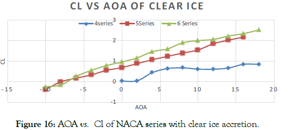
Figure 16: AOA vs. Cl of NACA series with clear ice accretion.
The above graphical analysis shows the drag coefficient over the chosen NACA series when there is no ice accretion on the airfoil. It is observed that the drag coefficient for 6 series is much lower when compared to the 5series and 4 series (Figure 17).
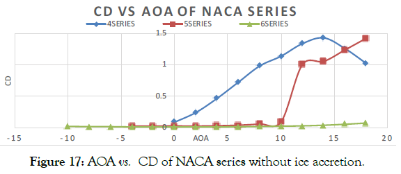
Figure 17: AOA vs. CD of NACA series without ice accretion.
The above graphical analysis after CFD results gives the Drag Coefficient Variation vs. AOA when there is acrretion of rough, irregular ice called rime ice on the three chosen NACA series for analysis i.e., NACA0012, NACA23012 and NACA643218 named as 4 series, 5 series and 6 series respectively. It is noticed that the effect of rime is greater on the 5series where the increment of drag is much more when compared to the 6 series and 4 series (Figure 18).
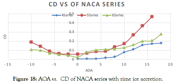
Figure 18: AOA vs. CD of NACA series with rime ice accretion.
The above graphical analysis after CFD results gives the lift Coefficient Variation vs. AOA when there is accretion of clear ice on the three chosen NACA series for analysis i.e., NACA0012, NACA23012 and NACA643218 named as 4 series, 5 series and 6 series respectively. It is shown that the clear ice results in drag increment which is more on NACA 4 series than the effect on 5 series and 6 series and this affects the aerodynamic parameters (Figure 19).
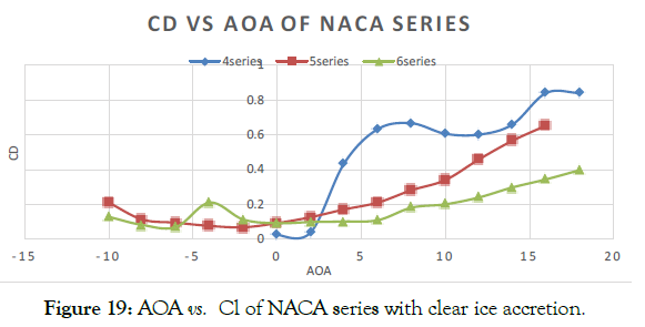
Figure 19: AOA vs. Cl of NACA series with clear ice accretion.
The primary objective of this research was to computationally analyse the aerodynamic parameters of airfoils of different NACA series and the ice accretion on these airfoils, namely NACA0012, NACA23012 and NACA643218 airfoils and the effect of ice accretion on the aerodynamic parameters. The primary objectives included the designs of the airfoils and the design of the clear ice and rime ice on the airfoils and how it affected the airfoil shape which in turn affected the aerodynamic properties. The ice accretion over the airfoil affects the performance and stability of the aircraft. With that in mind, we examined the computational results of 3 different NACA series and went through individual and composed comparison of the 3 airfoils. The CFD result gives us the effect on the lift coefficient and drag coefficient of individual airfoils with the ice accretion. Following can be concluded:
1. Clear ice affects the lift more when compared to rime ice for all airfoils except for NACA 6 series where the loss in lift is more due to rime ice.
2. NACA23012 with rime ice had a greater increment in aerodynamic drag coefficient when compared to NACA0012 and NACA643218.
3. To produce lift in airfoil for better performance during icing condition better NACA series needs to be predicted.
The co-ordinates of the airfoils of three different series were imported and tested computationally with the altitude range of 1000 ft. At this altitude, two kind of ice accumulation over the airfoil is considered for NACA0012, NACA23012 and NACA643218 airfoils and the effect of the ice on the aerodynamic properties is analysed using ANSYS. The analysis results show that NACA0012 airfoil with clear ice and rime ice creates high amount of drag as compared to other airfoils. The flow separation at the leading edge is completely affected due to the ice accretion. Instead of a single stagnation point, multiple stagnation points is created at the leading edge which increases the drag at higher altitude. Comparatively, NACA23012 airfoil and NACA643218 airfoil gives better results due to less contact surface at the leading edge. NACA643218 airfoil performs better due to the chord length and better aero-dynamical twist than the other two airfoils. The span-wise flow over the airfoil is completely linear to the normal flow direction thus slowing the vorticity range. Comparison result shows decrement in the coefficient of drag value in NACA 643218 airfoil which relatively indicates the performance of that airfoil. It is important to avoid the accretion of ice over the airfoil to have better performance and sustained efficiency, thus modern aircrafts make use of Anti-Icing and De-icing systems to remove the accreted ice from the aircraft wings. De-icing involves the removal of the accreted ice from the surface whereas Anti-icing does not allow the ice accretion over the surface or body of the aircraft. It is important to choose the NACA series which is the most efficient and resistant towards accretion of ice. From this CFD analysis it is concluded that NACA 6 series, i.e., NACA643218 is found to be efficient despite the accretion of ice compared to the 5 series and 4 series, i.e., NACA23012 and NACA0012 respectively.
Citation: Talasila ER, Ravi B (2021) Computational Analysis and Study of Atmospheric Ice Accretion on Different NACA Profile Series. J Aeronaut Aerospace Eng. 12:270.
Received: 31-Jul-2021 Accepted: 31-Aug-2021 Published: 08-Sep-2021 , DOI: 10.35248/2168-9792.21.10.270
Copyright: © 2021 Talasila ER, et al. This is an open access article distributed under the term of the Creative Commons Attribution License, which permits unrestricted use, distribution, and reproduction in any medium, provided the original work is properly cited.