Journal of Aeronautics & Aerospace Engineering
Open Access
ISSN: 2168-9792
ISSN: 2168-9792
Research Paper - (2019)Volume 8, Issue 1
In this paper NACA 2421 Aerofoil is analyzed at several angles of attack ranging from -200 to 200 and with the Reynolds number at 1.8 × 10⁵ and the velocity are 20 m/s. The co-efficient of lift and drag are compared with the standard values in the literature. Variation of pressure co-efficient is plotted in the form of contour. The aerofoil is designed in ANSYS and it is imported to Computational Fluid Dynamics and the variations of CL and CD with respect to various angles of attack is analyzed.
Computational fluid dynamics; Aerofoil; Angle of attack; Stalling
The NACA 2421 Aerofoil is designed for subsonic aircraft wings because of the better performance. Significance of improving a UAV performance can be done at very low Reynolds number 1.8 × 10⁵. Flow separation occurs normally due to very low inertia and very high viscosity [1]. In general NACA 2421 Aerofoil generates more lift in subsonic speed.
As per the Bernoulli’s principle if the pressure increases the velocity will decrease and vice versa [2]. Due to this pressure difference the lift is generated. In this work the flow separation over NACA 2421 unsymmetrical airfoil is observed and steps are taken to increase the lift to drag ratio [2].
In this work the stalling region is analyzed, and the various angles of attack is also analyzed [3]. For all type of NACA series the lift to drag ratio is very important criteria for the Aircraft design. Here the lift to drag ratio, critical angles of attack and stall regions are analyzed over the NACA 2421 Aerofoil with the various angles of attack [1].
SST turbulence model
Shear Stress Transport (k-ω) is used as a low turbulence model. It wills often the good behaviour in adverse pressure gradients and separating the flow [3]. It is used to predict the effect of turbulence.
(i)Turbulence Kinetic Energy:
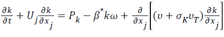
(ii) Specific Dissipation Rate:

F1-Blending Function
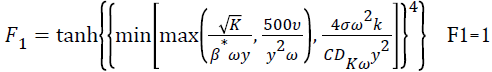 inside
the Boundary Layer
F1=0 in the free stream
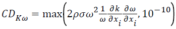
CDKω
Kinematic Eddy Viscosity
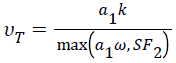
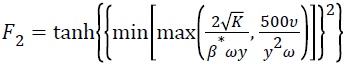
F2 - Second Blending Function
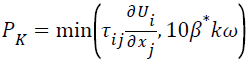
Pk- Production Limiter
• The SST model exhibit less sensitivity to free stream conditions,
• The Shear Stress limiter helps the
• k-ω model to avoid a build-up of excessive turbulence kinetic energy near o the stagnation points,
• The SST model provides the platform for additional extensions such as SAS and laminar to turbulence transition.
By using the geometry Modeller of Ansys Fluid Flow CFX, the imported co-ordinates are processed to prepare the model. Mesh generation is done by the polygonal mesh [3].
The most fundamental part of CFD problem is to mention the boundary conditions [4]. To conduct the simulation, the boundary condition of the problem some important conditions [3] are needs to be considered as given below.
Various Inputs and Values
• Analysis Type - Steady State,
• Fluid Velocity – 20 m/s,
• Fluid Density – 1 Bar,
• Mach Number – 1.8,
• Turbulence Model – SST,
• Fluid Viscosity – 1.8 × 10,
• Operating Temperature – 28 C.
Pressure plot and velocity vector
Basically if the angle of attack increases the lift is also increasing up to the certain limit. After the angle of attack reaches 15° the stalling and the critical angle of attack is starting [2]. If the lift is increasing, simultaneously the drag is also increasing (Figures 1-9; Table 1) [1,6].

Figure 1: NACA 2421 Aerofoil Ansys Model shows the Ansys Model of NACA 2421 Airfoil Section. The span length is 598mm and the chord length is 150mm.

Figure 2: NACA 2421 Aerofoil Mesh Profile shows the Mesh Profile of NACA 2421 Aerofoil section. The total elements are 77156 and the total nodes are 137164.

Figure 3: Angle of Attack at 50 shows the Pressure profile at the Angle of Attack of 50. Here the maximum pressure at the upper portion of the Aerofoil section is -4.229 × 10001 Pascal and the lower portion is -1.142 × 10002 Pascal.

Figure 4: Angle of Attack at 50 shows the velocity profile at the Angle of Attack of 50 and the velocity is 20 m/s.

Figure 5: Angle of Attack at 100 shows the Pressure profile at the Angle of Attack of 100. Here the maximum pressure at the upper portion of the Aerofoil section is -3.964 × 10002 Pascal and the lower portion is 0 Pascal. In the upper portion negative pressure is there. In the lower portion positive pressure is there. This pressure difference tends to the lift generation [5].

Figure 6: Angle of Attack at 00 shows the velocity profile at the Angle of Attack of 100 and the velocity is 20 m/s.

Figure 7: Angle of Attack at -150 shows the Pressure profile at the Angle of Attack of -150. Here the maximum pressure at the upper portion of the Aerofoil section is 1.47 × 10002 Pascal and the lower portion is 0 Pascal. The Angle of Attack at 150 is the stalling angle.

Figure 8: Angle of Attack at 150 shows the velocity profile at the Angle of Attack of 150 and the velocity is 20 m/s From the pressure and velocity plot the co-efficient of lift and the co-efficient of drag values are estimated [1].

Figure 9: α Vs CL, Computational Fluid Dynamics and the variations of CL and CD with respect to various angles of attack.
| α | CL CFD | CD CFD |
|---|---|---|
| 0 | 0.21 | 0.008 |
| 5 | 0.67 | 0.012 |
| 10 | 1.2 | 0.017 |
| 15 | 1.26 | 0.029 |
| 20 | 0.8 | 0.07 |
| -5 | -0.32 | 0.007 |
| -10 | -0.83 | 0.011 |
| -15 | -1.1 | 0.015 |
| -20 | -0.6 | 0.061 |
Table 1: CL and CD Ratios with Various Angles of Attack, the high lift to drag ratio will increases the performance of the aircraft.
• In all the cases up to the stalling angle if the lift is increases, simultaneously the drag is also increasing.
• The effective angle of attack is 70 to 140. Below 70 there is very low lift and after 140 stalling and the critical angle of attack is reached.
• At the angle of attack is at 50 the pressure is 2.452 × 10002 at the top and -4.735 × 10002 Pascal at the bottom.
• At the angle of attack of 150 the pressure is 2.46 × 10002 Pascal at the top and -6.159 × 10002 Pascal at the bottom.
• The flow separation will affect the generation of lift in the Aerofoil section.
Citation: Madhanraj VR, Shah DA (2019) CFD Analysis of NACA 2421 Aerofoil at Several Angles of Attack. J Aeronaut Aerospace Eng 8: 215.
Received: 02-Jan-2019 Accepted: 31-May-2019 Published: 04-Jun-2019 , DOI: 10.35248/2168-9792.19.8.217
Copyright: © 2019 Madhanraj VR, et al. This is an open-access article distributed under the terms of the Creative Commons Attribution License, which permits unrestricted use, distribution, and reproduction in any medium, provided the original author and source are credited.
Sources of funding : -