Journal of Aeronautics & Aerospace Engineering
Open Access
ISSN: 2168-9792
ISSN: 2168-9792
Research Article - (2015) Volume 4, Issue 1
According to Quantum Electrodynamics (QED), a hidden source of great momentum and energy, called the EM Quantum Vacuum, fills the Universe. A Quantum light-sail will use refraction to induce asymmetric boundary conditions in the isotropic EM radiation pressure of the Quantum Vacuum. In terms of Newton’s First Law, these asymmetric radiation-pressures act as outside-forces that push harder on one side of a light-sail than on its opposite side. This radiation-pressure will provide the motive force for a new class of macroscopic prime-movers, a kind of massless propulsion; a new environmental-energy conversion device.
<Keywords: Propellp physics; Solar sails; Light sails; Interstellar propulsion; Space drive; Reactionless propulsion; Quantum optics; Environmental energy conversion; Massless propulsion
According to Quantum Electrodynamics, QED, the EM Quantum Vacuum fills the Universe [1]. If it could be seen, it would look like the tiny flashes of static-snow that are seen on televisions in-between channels. It is believed to consist of photons that momentarily manifest then promptly disappear. NASA’s Breakthrough Physics Propulsion Program report says that it might be possible to induce Casimir-like propulsive forces by developing new means of imposing asymmetric boundary conditions on the EM Quantum Vacuum [2] ractical approach to accomplishing that is explored in this paper.
Just as sails on ships and vanes on windmills capture the costfree energy and momentum of the wind, so also, Quantum Sails will be driven by inducing asymmetries in the energy and momentum of the isotropic radiation pressure of the EM Quantum Vacuum. This radiation-pressure will provide the motive force for a new class of macroscopic prime-movers, a kind of mass-less propulsion, a new environmental-energy conversion device. All of this is reconciled with the Laws of Thermodynamics and the Laws of Motion.
The purpose of this paper is not to prove that any of this is certain; rather, a main point is to establish that the proposed experiment is worthwhile. It is also intended to recruit individuals who will help join, assemble, fund and equip a research team to design and produce the prototype Quantum-Sail that is described in this paper. To accomplish these two objectives, it is necessary to overcome a large number of unwarranted theoretical objections to this sort of proposal. Rather than being some sort of new discovery, this paper is a novel perspective on settled science. Although the proposed device is simple, its merit is not apparent if the science that it is based upon is not first re-articulated from this new perspective.
According to Quantum Electrodynamics, the Quantum-Vacuum Zero-Point Energy field is what is left in space even if all matter and heat were removed. It is believed to consist of particle-pairs that pop into existence then vanish a short time later. Some of these particles are photons. Its photons continuously appear in every possible wavelength. Then they vanish after traveling about half of a wave-length.
The EM Quantum Vacuum Radiation Pressure can be derived from energy values that can be experimentally detected. These values and their relationships are described by Planck’s Black Body Radiation Spectrum Formula. Each energy value is represented by u. Planck’s Constant is h.
u=hω (n+1/2); { n=0, 1, 2, 3 . . . n, n+1} (1)
The existence of the Zero Point Energy Field is most clearly seen in the instance where n=0; this leaves Equation. 2.
uzpe=hω/2 (2)
The radiation that is attributable to emissions from atoms is given by n, which is always a whole number. However, actual readings of Black Body Radiation reveals the extra term: 1/2. So in addition to the part of the Black Body Radiation field which originates in orbital transitions inside of atoms, another field is present. It would be detected by itself when n equals Zero. Zero-Point Energy, uzpe, is the energy that comprises the EM Quantum Vacuum.
Planck’s constant is the energy per cycle, the energy per single photon. Planck’s constant is represented by the symbol h or h; ω is light frequency in radians per second; f is frequency in cycles per second.
(Eq. 2)=h ω/2=[(h/2π) (2π f)/2]=uzpe=h f /2
A single photon is one wavelength long; 1/λ3 gives the total number of photons of one wavelength that can fit into one cubic meter. (Equation. 4) gives the total energy of quanta of that one wavelength that is in a cubic meter of space.
c=f λ
Integrating uzpe ( f ) df sums the energies of all photons of every frequency that can simultaneously occupy one cubic meter in a given range of frequencies.


Ludwig Boltzmann proved that the isotropic radiation-pressure Pr, that is acting uniformly on a surface is equal to the energy-density above the surface, divided by three.
In practice, one can justify not counting wavelengths that are larger than λ specified since one only needs to specify wavelengths that significantly impact the material that has been chosen. The energy density of progressively longer wavelengths quickly becomes insignificant. This is because every two-fold increase in wavelength is accompanied by a sixteen-fold decrease in energy-density. This is due to the λ-4 term. Likewise, consideration of ever-smaller wavelengths also converges rapidly on irrelevance for the present purposes; this is because matter rapidly becomes ever-more transparent as ever-smaller wavelengths are considered.
Henrik Casimir is credited with being the first person to propose using the Radiation Pressure of the EM Quantum Flux to move a physical object [3] described what would occur if EM Zero-Point Energy really exists. In 1948, he proposed a thought experiment. He described two electrically-neutral, electrically-conducting, parallel plates. At least one plate could move freely. They would be separated from each other by a very small distance. He pointed out that these plates would prevent the EM Quantum Flux from forming photons with wavelengths that were too long to form between the plates.
In Figure 1, the smaller, purple waves represent all of the wavelengths that can form both inside-of and outside-of the space between the plates. Since the smaller waves are equal and opposite to each other, they exert no net forces on the plates; however, the longer red wavelengths can only form outside of the space between the two plates since they are too long to fit between the plates. The inward-directed Radiation Pressure, outside of the plates, consists of all possible wavelengths. This is because all-possible wavelengths can form outside of the confines of the space between the Plates. The longer (red) wavelengths move the plates inward since there are no long, red wavelengths inside the cavity to counteract them by pushing outwardly.
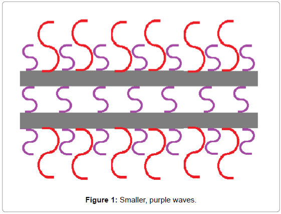
Figure 1: Smaller, purple waves.
the two plates since they are too long to fit between the plates. The inward-directed Radiation Pressure, outside of the plates, consists of all possible wavelengths. This is because all-possible wavelengths can form outside of the confines of the space between the Plates. The longer (red) wavelengths move the plates inward since there are no long, red wavelengths inside the cavity to counteract them by pushing outwardly.
Suppose Casimir’s original Radiation Pressure Theory correctly models a real physical process. This means that the plates are not exerting any significant forces on each other. Instead, the plates are effortlessly altering the EM Quantum Vacuum Density by simply being there. They are then moved because of the radiation-pressure differences on opposite sides of each plate. They are moved by the energy and momentum of the Radiation Pressure of the EM Quantum Flux. In other words, no human is providing this energy. This is energy that would have been there, in the environment, whether or not anyone chose to use it. Harold Puthoff, Director of the Institute for Advanced Studies at Austin, Texas, has pointed out that this energy is left behind as heat if the plates collide. In other words, Zero-Point energy has already been used to propel real objects. Again, these plates constitute a kind of Quantum Sail since they are moved by induced asymmetries in the radiation pressures in the EM Quantum Vacuum.
If Casimir Plates did not move, that would violate the Zeroeth Law. This is because the freely-moveable Plate is located directly between a high energy-density radiation-pressure region and a low-energy radiation-pressure region; therefore, it would have to move.
The First Law is not violated. This is because the energy that is entering the system as a high-energy flux of photons is equal to the work and low-energy photon flux that is leaving system as heat.
The Second Law is not violated. This is because an already-existing high energy-density, low entropy photon flux is crossing the system boundary, performing work and shedding high-entropy, low energydensity heat which then exits across the System Boundary. Therefore Entropy is increasing and energy density is decreasing, just as they should do.
The Third Law concerns the usual inability of energy to transfer in the absence of two differing Thermal Reservoirs. It is not the machine that is exceptional in this case. Rather, the Quantum Flux itself is defined as the energy that remains in otherwise empty space, when all heat energy has been removed. This is one reason why it is called Zero- Point Energy (ZPE.) Of course it is also still present at all non-zero temperatures.
ZPE literally has no thermal potential because differences in energy potential cannot flow together. This is because each generation of particles vanishes before they can redistribute themselves. Each generation of particles is replaced by a new generation of particles that appears in the same general distribution as the previous generation of particles appeared. Casimir’s Plates move because they store multiple generations of energy that is collected as the photons collide more with one side of each plate than with the opposite side.
Though the Quantum Flux is non-thermal, its spectrum is, highly energetic, especially at wavelengths below 50 nm. In other words, being at Zero-Temperature does not mean that its energy potential is Zero. Again, one is using the low-entropy, high-energy density Radiation Pressure of very-intense, very-small wavelengths to do work. That work is dissipated as low-energy, high-entropy wavelengths of infrared radiation.
Basically, the Third Law comes into play more abstractly: High and low frequencies always exist in the ZPE Spectrum at all temperatures. Even at Absolute Zero Degrees, the high energy, low-entropy wavelengths function as the high-energy reservoir and the cool heatsink of space still serves as the low-energy heat-reservoir, as usual. So a high energy reservoir and a low energy reservoir are both still present. So, in principle, the Third Law is still being observed. This adaptation of the Third Law is no more extraordinary than when the Third Law is adapted to cover systems that require non-thermal differences in electrical potential or hydraulic pressure.
Many object that using some of this energy before it winkedout would change the amount of energy remaining in the Universe. This depends entirely on where one draws the system-boundaries of the Universe. On the one hand, if one defines the Quantum Flux mechanism as part of the Universe then, perhaps, energy is not really being created and destroyed. Instead, it might be alternating between a hidden state and a manifest state. This is the essence of Paul Dirac’s Theory of a vast Sea of Particles that alternate between a positive energy level and a negative energy level. Any energy that left the Quantum- Flux would then have begun in the Universe and then remained in the Universe.
On the other hand, if one posits that the Quantum Flux is not part of the Universe, then he is admitting that energy can enter and leave the Universe. Therefore, one would have no basis for assuming that matter and energy could not temporarily accumulate in one Universe while another Universe is temporarily depleted. Perhaps this energy would be passed back and forth more or less equally over time. These musings are no more- or less- fanciful than insisting that one even can know if the energy-balance of the universe has to match our small-minded, pathetically-uninformed expectations. In other words a quantum sail is not required to return an equal amount of energy to the Quantum field any more than one would require a coal-fired steam plant to return an equal quantity of coal to the ground.
The Casimir Effect is very real; it currently presents severe problems in Microscopic Electromechanical Machines, MEMs. It causes sticktion which means that the small clearances that are between small parts form unintended Casimir Cavities. In other words, Casimir Forces tend to jam very-small parts together so that they cannot function properly. So already, the Casimir Effect is a force to be reckoned-with. However, one man has found a potentially-practical method of utilizing the effect.
Fabrizio Pinto has obtained a patent for reciprocating Casimir Plates [5]. Semiconductor plates would alternate between a conducting and non-conducting state to turn the Casimir Effect off and on. Unfortunately such an approach may only produce small forces, and motions that are less than a micrometer in length. It may very well prove to be useful for microscopic machines; but it may be impossible to use it to create useful macroscopic forces. This is due to the difficulty of maintaining large parallel surfaces at nano-scale separations. It also would not be useful for propellantless propulsion.
Instead of using a pair of plates, a single isolated plate will impose asymmetric boundary conditions with the EM Quantum Vacuum on its two sides. These asymmetric conditions will cause a single plate to experience different radiation pressures on its two sides; this will cause a net force to act on the plate.
This Quantum sail could be easily distributed over large areas. Also, many layers of sails could be stacked; they would be separated by a material that allows the EM Quantum-Flux to manifest within it. In this way, macroscopic combined-forces might be obtained, even if individual layers contribute extremely small forces. Such an arrangement would be useful both for propulsion and for environmental-energy conversion.
Can the two sides of a single plate interact asymmetrically with the radiation pressure of the EM Quantum Vacuum and experience a net force? Propellant-less Propulsion is the sort of concept that will cause many readers to quickly put this paper down. That is because, on its face, it seems like a hopelessly absurd thing to attempt. NASA’s Breakthrough Physics Propulsion Program (BPPP) evaluated possible avenues of novel research. It hoped to identify new insights and methods that might enable science to surpass current expectations of what is considered possible. The BPPP authors examined many proposals; electric rockets, nuclear rockets, laser powered sails; interstellar ramjets. No mass-based propulsion methods appear adequate to take anyone, even just to the second-nearest Star, in a single lifetime. Therefore, the BPPP was particularly interested in identifying avenues of research that might lead to Propellant-less propulsion. Propellant-less Propulsion would not need on-board reaction mass. This is important because the reaction-mass requirement of rockets is the major part of what makes them fuel-hungry, large, expensive and slow.
NASA’s Breakthrough Physics Propulsion Program final report mentioned the possibility of developing a Quantum light-diode sail [2]; it would let more EM Quantum Vacuum radiation pass through the diode from one side than from the opposite side. This would cause the isotropic EM Quantum-Vacuum radiation-pressure to exert a net force toward the less-transparent, more-reflective side of the Quantum- Diode. In other words, instead of using Newton’s Third Law which requires reaction-mass, one would use the radiation-pressure of the Quantum-Vacuum as an outside-force, in accordance with Newton’s First Law.
It sounds theoretically impossible to derive a net force from equal and opposite influxes. It is tempting to dismiss this entire notion by simply invoking Conservation of Momentum; however, this general objection is easily refuted by a simple example, a mechanical diode for rubber balls: Two teams of astronauts throw equal and opposite numbers of rubber balls at a wall that is floating in Space between them. At this point, most people insist that one should already know that the wall will not be moved in either direction. They will argue that all of the forces that are applied to the balls are equal and opposite; therefore, they say that whatever one side of the system accomplishes, the opposite side of the system must undo it. In other words, they are saying, since the applied momentum sums to zero, then so must the final momentum sum to zero. This much is true, but it still does not mean that the wall is not moved.
What if the wall itself responds differently to the two influxes of balls? What if the wall itself introduces asymmetric reaction-forces? If the wall is made of little doors that only open in one direction, then half of the balls will impart a full-measure of momentum to the wall as they bounce off of the one side where the doors stay closed; but the remaining balls will only impart a small amount of their momentum to the wall, in the opposite direction, as they push the doors open and continue onward. In other words, a door experiences a stronger collision-force from a rubber ball if that door remains closed than from a rubber ball that pushes on through the door. This happens because the collision-force that a given rubber ball exerts on a door must equal the reaction force that door applies to the rubber ball. On one side, that reaction-force is limited to whatever small amount of force it takes to push a door open. In effect, the balls on the other side encounter a solid wall.
It is quite remarkable that two equal and opposite influxes can indeed impact the same wall asymmetrically. This does not prove that one could in-practice make a light-diode; but it does prove that this sort of thing is not impossible from the standpoint of Momentum Conservation. In this example, the doors experienced different reaction forces on their two sides. Similarly, in the next example, a two-sided mirror is approached by equal and opposite influxes of EM Quantum- Vacuum radiation-pressure. Again, the reaction-forces are different on each of the two sides. In this case, a difference in pressure arises on opposite sides of the two-sided mirror because one side is covered with a highly-refractive material and the opposite side is bare or is covered with a low-refraction material.
This paper proposes a realistic, simple solution to a profoundly difficult problem: The EM Quantum Flux Radiation-Pressure is equally energetic in every direction. Put another way, this radiation-pressure normally pushes equally hard on opposite sides of most objects. All of these forces would normally be totally used-up, just counteracting each-other. Since these forces are normally equal and opposite among themselves, a single, isolated two-sided mirror floating in Space would normally remain stationary (Figure 2).
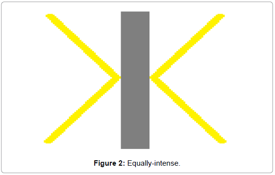
Figure 2: Equally-intense.
The two yellow rays represent the light of the EM Quantum- Vacuum. In particular, they represent the fact that its light rays strike any given point on the mirror at mostly non-perpendicular angles.They also represent the fact that, usually, the light rays of the EM Quantum-Vacuum would strike a two sided mirror equally on each side. Therefore, this floating, two-sided mirror would not be pushed in either direction by the light of the EM Quantum-Vacuum.
The problem in Figure 2 is not merely that the rays of light are equally-intense. Rather, the difficulty lies in the fact that they are equally-intense and opposite.
Figure 3 illustrates one way to obtain a net force from two beams that are equally-intense. Two equally-intense beams of light are striking a two-sided mirror that is floating freely in Space. The beam on the left strikes the mirror at a 30 degree; this angle is more-perpendicular to the plate than the beam on the right which is striking at a 60 degree angle. The force of the light striking each surface is given by F cos θ; F cos 30 is greater than F cos 60; therefore, the beam on the left hits the plate harder than the beam on the right. Consequently, the plate will be pushed to the right, even though the beams are equally-intense. This could be done with two equally-intense lasers.
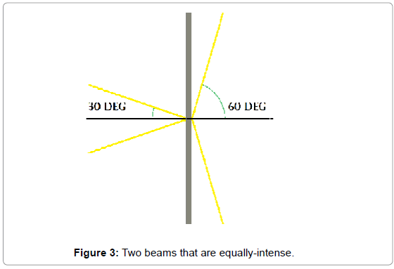
Figure 3: Two beams that are equally-intense.
sIn Figure 4, two equal and opposite beams of light remain equallyintense but become non-opposite. One light-beam approaches the blue refractive-material at a sixty-degree angle that is equal and opposite to the light-beam that is approaching the bare side of the mirror on the right, at sixty degrees; but then the beam on the left is refracted. The light on the left strikes the mirror at a thirty degree angle which is steeper than the light that strikes the right side of the mirror. Therefore, a net force to the right acts on the two-sided mirror, just as in Figure 3. Many experiments, for many years, proved that, under these circumstances, light does in-fact exert a stronger force on a mirror that is in a refractive material, than the same light exerts on the same mirror when no refractive material present [6-10]. The forces that act on the refractive material will be discussed later in this paper.
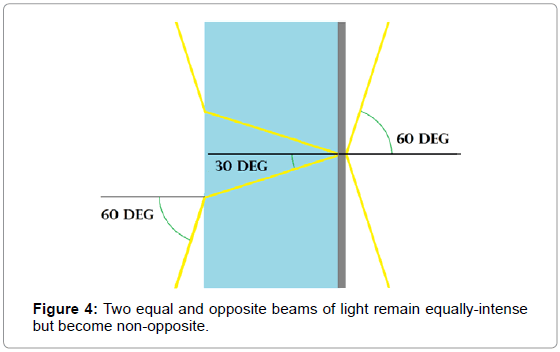
Figure 4: Two equal and opposite beams of light remain equally-intense but become non-opposite.
As with the rubber-ball diode, the applied momenta start out equal and opposite to each other, yet the mirror is moved. In the case of the ball-diode, the two equal and opposite influxes of balls applied asymmetric collision forces to the doors because the doors applied asymmetric reaction-forces to the balls. With the refractive mirror system, the refractive material and the light exert refraction forces on each-other; thus, the path of the light is altered on the refractive side of the mirror and not altered on the bare side of the mirror, as in Figure 4. This is true for every equal and opposite pair of light rays that approach the system. It will also be true of every photon of the EM Quantum Vacuum that is refracted by the refractive material, from every possible angle.
So far, the refractive mirror setup has had light entering a refractive surface that is parallel to the mirror. This arrangement, shown again in Figure 5, yields a result where the force on the mirror increases. The yellow lines represent the momentum vectors of the light beam. The red arrows represent momentum that is perpendicular to the mirror. The purple arrows represent the momentum component of the light that is parallel to the mirror. It is important to note that changes in these vector lengths are a consequence of the fact that the angle of the ray of light changes, relative to the mirror. The red perpendicular momentum vectors verify this change in momentum; the red perpendicularmomentum vector is longer,after the light enters the refractive material.
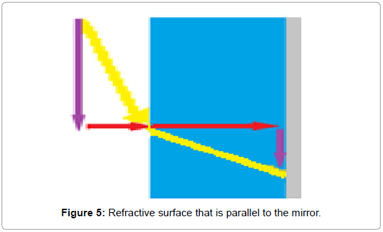
Figure 5: Refractive surface that is parallel to the mirror.
Other times the force on the mirror will decrease inside a refractive medium. Figure 6 demonstrates how one can obtain this result with an experimental setup that is similar to the one in Figure 5.
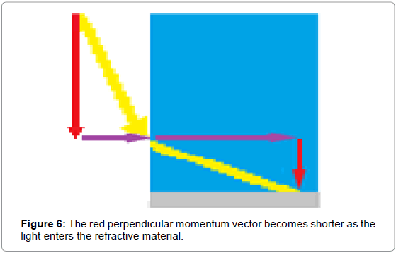
Figure 6: The red perpendicular momentum vector becomes shorter as the light enters the refractive material.
This time, the light enters the refractive material through a surface that is perpendicular to the mirror. Therefore, in this case, the refraction is causing the light to strike the mirror inside the refractive material at a shallower angle than if the refractive material were not present.
Therefore, this time, the force on the mirror is less when the refractive material is present. This can be verified by comparing the momentum component vectors. In Figure 5 the red perpendicular vector became longer as the light entered the refractive material. In contrast, in Figure 6 the red perpendicular momentum vector becomes shorter as the light enters the refractive material. The system in Figure 6 is nothing more than a trivial variation of the system in Figure 5.Comparing Figures 5 and 6 also reveals how momentum is transferred between the component vectors as the light refracts.
The mirror in these arrangements will definitely experience a net force; [6] but, does the refractive-force that acts on the refractivematerial exert a force that is equal and opposite to the net force that acts on the mirror, so as to render the entire system motionless? The answer to this question has long-been obscured by the century-old Minkowski-Abraham discussion concerning [7] the momentum of light inside a refractive-medium.
According to Minkowski, light acquires extra total momentum as it enters a more refractive medium. It is said to increase by a factor that is equal to the refractive index of the medium [8]. According to Abraham the total momentum will decrease by a factor that is equal to the inverse of the refractive index of the medium [9]. Each of these hypotheses is seemingly-supported by an abundance of experimental observations. These two viewpoints are examined in the following discussion.
A refractive material covers the back side of the mirror in Figure 7; it is represented by the blue area. The yellow rays represent the average of all of the rays that are approaching each mirror.
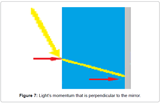
Figure 7: Light’s momentum that is perpendicular to the mirror.
In Figure 7, the red arrows represent the component of the light’s momentum that is perpendicular to the mirror. The red arrows in Figure 7 show what would happen if momentum were conserved in the expected way. These two rays are shown as though they had the same perpendicular vector-momentum both before- and after- the ray enters the refractive material. The perpendicular momentum outside of the refractive material is represented as being equal to the perpendicular momentum that is inside the refractive material.
Figure 8 shows what really happens. The magnitude of the perpendicular momentum vector is actually greater, inside the refractive material, even though it is still the same ray of light as it was outside of the more-refractive medium.
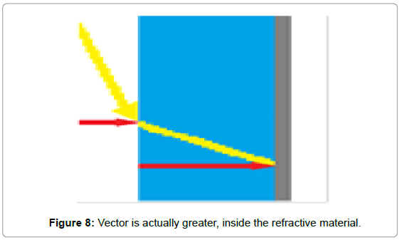
Figure 8: Vector is actually greater, inside the refractive material.
Figure 9 consists of a two sided mirror. The back side of the mirror is covered with the refractive material. The front side is bare. Equal and opposite light influxes approach both sides of the entire system. Why doesn’t Figure 9 outright-prove that one can use refraction to get a net force from equal and opposite influxes of light? Minkowski took this dilemma at face value and concluded that the beam of light somehow actually acquires extra total momentum as it enters the refractive medium. No causal mechanism has been established; this is just as inexplicable today as when Minkowski first made this famous conjecture. This so-called extra total-momentum is called Canonical Momentum. He took the position that this situation would still be consistent with conservation of momentum, as long as the light gains or loses the same amount of extra momentum as it enters and exits the refractive medium. In other words, he was adding extra momentum into his math for the light that was inside the more-refractive medium. Therefore, to salvage his approach to the problem while still Conserving Momentum, he had to subtract this extra momentum out of his figures for when the light exited the refractive medium. Again, no causative mechanism is proposed. This would also mean that any extra-momentum forces that are acting on the mirror because of this Canonical momentum would have to be counteracted by refractive forces that operate in the opposite direction, as the light enters and exits the refractive medium.
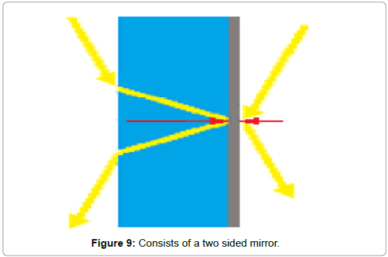
Figure 9: Consists of a two sided mirror.
In Figure 10, the green arrows indicate the direction that the refraction forces would have to act if Minkowski was correct. On the one hand, if Minkowski is correct, then there would be no net force acting on the entire sail system (Figure 11). On the other hand, if there is no equal and opposite refraction force to counteract the net reflection force that acts on the mirror then Minkowski is mistaken; then, there will be a net-force acting on the entire sail system as is shown in Figure 12.
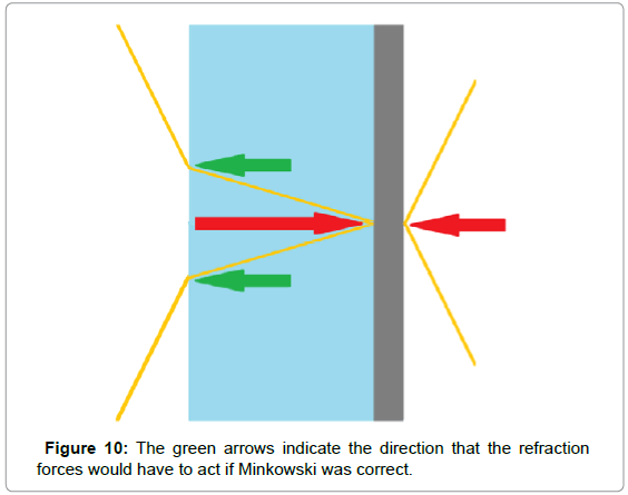
Figure 10: The green arrows indicate the direction that the refraction forces would have to act if Minkowski was correct.
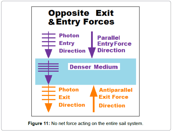
Figure 11: No net force acting on the entire sail system.
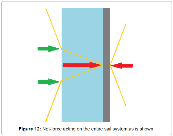
Figure 12: Net-force acting on the entire sail system as is shown.
As light enters the more-refractive material, it slows down. It is as though it is exerting deceleration reaction forces on the refractive medium. These forces are analogous to a car that imparts a forwarddirected force to the roadway as it decelerates upon entering a school zone. This forward-directed force is directed into the slow-speed zone.
Surprisingly, it turns out that a force also acts back toward the refractive medium as the light exits the refractive medium [11]. This exit force has been experimentally demonstrated. A laser was shined through a glass fiber and a recoil force was noted; it bent the fiber as the light exited out the end of the fiber [12]. Loudon and Baxter also claimed this result in their paper on Poynting’s work [13]. Analogously, this time, the car in the example is exerting backwards-directed forces on the roadway, as it pushes against the road to accelerate while leaving the school-zone. In other words, the refraction-forces that act on the refractive material, are always pointing toward the refractive-material, both when the light is entering the refractive-material and when it is exiting the refractive-material.
In Figure 11, these entry and exit forces are equal and opposite-to each-other; however, they are equal and opposite only because, in this particular instance, the light enters into one side of the more refractive material and exits from the opposite side of the more refractive medium; but this is not always the case.
The actual refraction forces are shown with the green arrows in Figure 12. Both refractive forces are still directed toward the refractive medium; but in this case, “exerting a force toward the refractivematerial” means the entry-forces and exit-forces are both exerted in the same direction since the light both enters and exits from the same side of the refractive material.
This time, the refraction forces do not counteract each-other. Neither do they counteract the net reflection force that is acting on the mirror that is implied by the longer red arrow. All three forces are directed toward the back of the mirror. Therefore, a net-force will act on the entire sail system, including the refractive material as well as the mirror.
The green arrows show that both the entry- and exit-forces act in the same direction as the net reflection-force.
Extra energy and extra momentum are positively not magically appearing inside of the refractive material, not temporarily, not at all. The same amount of total-energy and momentum-amplitude are present on the bare side of the double-mirror as on its refractive side, inside the refractive-material; but that energy is reorganized by the refractive-forces. The total momentum magnitude does not change as the light enters the refractive material; instead, its direction of application changes.
Suppose a car is coasting in a circle, its speed is a steady ten miles per hour, but its velocity constantly changes. Its velocity changes only because its motion changes direction. Even so, its speed and its momentum-amplitude remain the same but are continually expressed in new directions. Its kinetic energy also changes direction, but it also retains the same kinetic-energy amplitude in each new direction. In Figure 13, energy and momentum are constantly transferring between the horizontal vectors and the vertical vectors. So also can the parallel vectors and the perpendicular vectors of the light exchange momentum and energy when refraction forces cause the light path to change direction.
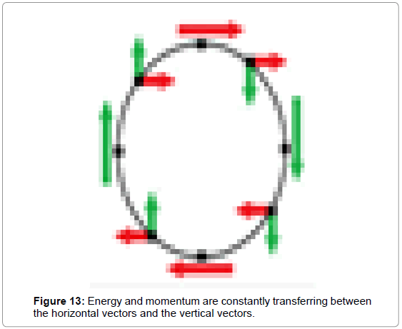
Figure 13: Energy and momentum are constantly transferring between the horizontal vectors and the vertical vectors.
The momentum of the car was altered by the forces that acted between the tires and the road; likewise, the momentum of the turning light is altered by the refraction forces; therefore, its momentum and energy change direction but they do not change amplitude. The light is just as energetic now as it was before it changed direction. Each photon takes its energy and translates that energy to a different orientation as it decelerates into the refractive material. The photons and the refractive material exert forces on each other, forces that are directed perpendicularly toward one side of the mirror.
There are two ways to turn a vehicle: One can turn some or all of the wheels in the manner that one turns an automobile’s front wheels; alternatively, one can make some wheels travel faster or slower than the other wheels like the way a Segway turns. In Figure 14, each wheel of these Segways is programmed to individually rotate slower when it crosses over onto the grass. The outside wheels had to slow down first since they were first to enter the grass. These outside wheels make the light-brown tracks in the grass. They start going slow, sooner than the inside wheels. Meanwhile, the still-faster inside wheels travel further in the same amount of time. The dark brown tracks show the longer distance that is traveled by the opposite wheel on each Segway, in the same amount of time. This has the effect of turning the vehicle since the faster wheel is pivoting around the slower wheel.
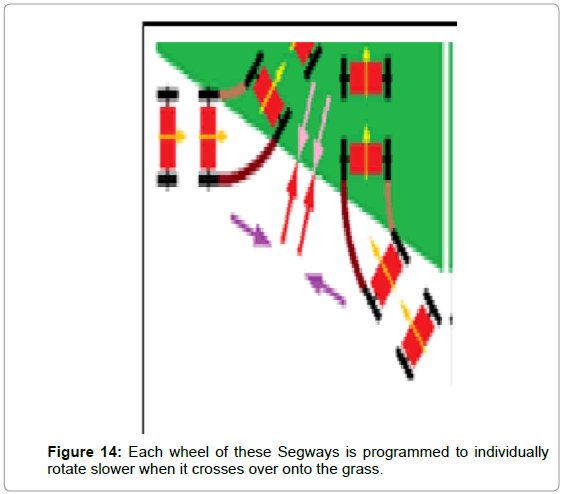
Figure 14: Each wheel of these Segways is programmed to individually rotate slower when it crosses over onto the grass.
Likewise, the refractive material exerts forces on the refracting light; first, it slows one side of a light particle; an instant later, it slows the opposite side of the same light particle as it finishes turning the particle. In other words, the fast side of a photon pivots around its slow side as it is crossing over into the more refractive material. The photon exerts a force toward the refractive material. It slows down because the refractive-material exerts an outward-directed reaction force on it. Really, each photon is pivoting around this reaction force.
In Figure 15, the average-ray (yellow) that is approaching the refractive material on the back of the sail, is equal and opposite to the corresponding average ray that is approaching the bare mirror that is on the front of the sail; this can be verified by observing their short red perpendicular component vectors; they are equal and opposite.
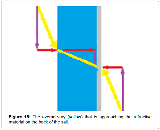
Figure 15: The average-ray (yellow) that is approaching the refractive material on the back of the sail.
As the light enters into the refractive material, the parallel momentum of the light decreases; it decreases by the same amount that the perpendicular momentum increases. This can be verified by comparing the parallel momentum-component vectors of the light before and after it enters the refractive-material: The purple parallel component vector is longer outside the refractive-material but shorter inside the refractive material. However, the red perpendicular component vector was lengthened as it entered the refractive material. This implies that momentum and energy are being caused to flow less in the parallel direction and more in the perpendicular direction as the light is bent by refraction.
As the light passes into the more-refractive material, the entire beam turns. The direction of its total momentum magnitude has also turned as the light resumes traveling in a straight line, but in a new direction. It is now acting more-perpendicularly to the mirror inside the refractive-material than is the light that is acting in the opposite direction on the bare side of the mirror; therefore, the reflection force that is acting on the refractive side of the mirror is stronger than the reflection-force that acts on the bare side of the double-mirror. This can be verified by comparing the momentum-component vectors that act on both sides of the double-mirror, in Figure 15. The red perpendicular component, inside the refractive medium, is longer than the red perpendicular component that is acting in the opposite direction, on the bare side of the mirror. Again, it is critical to recognize that the vector lengths are a function of the changes in the angle of the yellow light-vectors, relative to the double-mirror.
As the light enters the refractive medium, the short red perpendicular momentum vector outside of the more-refractive material becomes longer, inside the refractive medium; but the parallel momentum vector (purple) is longer outside of the refractive-material and shorter, inside the refractive-material.
The project can be broken-down into three phases. Phase One would consist of testing the Refractive Mirror Concept using lasers to make certain that equal and opposite light beams really can simultaneously produce a net force in a refractive-mirror system. Confirming that premise will provide a reason to persist in solving any problems that arise uniquely at smaller wavelengths, using the distinctively ephemeral photons of the EM Quantum Vacuum.
The second phase of research would involve trying to measure Quantum Vacuum EM radiation forces that are acting on a single-sail system. It appears likely that net pressures of two- or three-hundred Pascal are within reach of a reasonably modest research effort. This does not sound like much pressure or energy; but such a sail would easily lift thousands of times its own weight, since it could be as small as a few-hundred nanometers in thickness; however, it would have to be mounted on a heavier substrate. (The sail cannot be exposed to the air when it is supposed to be exploiting VUV wavelengths since these wavelengths do not form in ionizable mediums such as air.)
A third phase of research will involve stacking many layers of sails to form a meta-material that is thousands of sails thick. There is no particular constraint on how broad an area might be covered by each sail. In Figure 16, the material with the lowest refractive index is light blue. It is the material that separates the various sails. The material that has the highest refractive index is dark blue. The gold color is gold or some other highly reflective metal. Individual gold/dark-blue pairs comprise individual sails. Generally speaking, the metal-layers must be at least three times the thickness of the skin-effect for the wavelengths of interest; it can be much thicker if this is more convenient. The light blue, low-refraction material must have a thickness that is at least two times the wavelengths of interest; but again, it can be as much thicker as is convenient. The dark blue highly refractive material must be less than a quarter of the smallest wavelength of interest. This is because the photons of the Quantum-Vacuum only travel about half of a wavelength before vanishing.
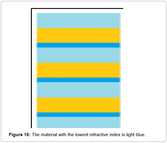
Figure 16: The material with the lowest refractive index is light blue.
Smaller wave-lengths are much more powerful but the metal is more transparent to smaller wave-lengths so it may require much modelling, trial and error to determine what wavelengths will prove to be optimum with which materials.
A prototype might resemble many layers of Mylar. It might consist of thin aluminum sheets that are coated with plastic on one side and a highly refractive substance on the opposite side. Many yards of this could be wound up and cut off a large flat roll, already stacked. It may be useful to use a vitreous metal sheet to eliminate the crystal structure of the metal to enhance its smoothness.
It is necessary to recruit investors, and experts in photonics and in optical films to design and perform these experiments. It will require an optical lab with lasers and equipment for measuring very small forces. Please contact the author for participation information.
Equation. 10 is based on Eqution. 9; Eq. 10 gives the net pressure Pr that acts upon a two-sided refractive-mirror. The net pressure is obtained by subtracting the unaltered pressure that acts on the mirror’s bare side from the increased pressure of the refractive side of the mirror. (n1 is the refractive index of the material that coats one side of the light-sail. n1 is the index of the most refractive material. n2 is the refractive index of the material that separates the different sails).
Net Pressure= 
Equation. 10 gives the ideal net pressure assuming that the refractive index n1 is two. It uses the following equation.
(n1 is the most refractive material. n2 is the refractive index of the material that separates the different sails)
Pressure=
Figure 17 is based on Eq. 10; it shows the pressures that can be expected by exploiting a given wavelength and all wave-lengths that are greater than that wavelength. For example, exploiting 50 nm wavelengths would yield greater than atmospheric pressure if it was just one hundred layers deep.
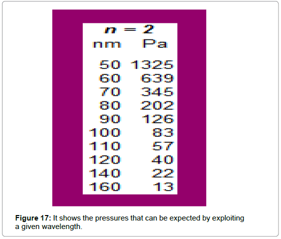
Figure 17: It shows the pressures that can be expected by exploiting a given wavelength.
The ball-diode proves that equal and opposite influxes can, in principle, be tapped to produce a net force, and to extract energy from equal and opposite influxes. Casimir’s original interpretation of the Casimir phenomenon was that it was driven by asymmetries in the radiation-pressure of the EM Quantum-Vacuum. Casimir’s plates can be considered a kind of experimentally-confirmed Quantum light-sail. Therefore it is reasonable to try to develop other methods of inducing useful asymmetries in the EM Quantum-Flux.
For many years, various experiments have revealed that light can exert more pressure on a mirror if it is covered with a refractive material than if it is not covered with a refractive-material. However, this idea has acquired extra-baggage in the form of incorrect assumptions concerning the direction of the refractive forces that act on the refractive material. According to these incorrect assumptions, there could be no net force acting on the entire system. According to the experimentally-confirmed facts concerning refractive forces, a net force should act on the entire proposed system.
The simplest explanation is that the momentum-magnitude and energy intensity of a beam of light remains constant as the beam is refracted and changes direction. Therefore, it may be possible to use refraction to cause the isotropic radiation-pressure of the EM Quantum Vacuum to exert a net force on a passive Light Sail.
The ability to lay down many layers of mirrors and refractivematerials means that even very modest forces may potentially be combined to produce practical net forces. This may have potential for energy production and vehicular propulsion of all kinds, using currently available equipment and techniques.
Although every separate aspect of this experiment has been experimentally verified, seemingly, no one has simultaneously measured the refraction forces and the reflection-forces to determine if a net force can be generated by the refractive mirror system that has just been discussed. Again, the point of this paper was not to prove that this idea must work; rather, the point is to stimulate discussion and action on the proposal and to justify performing the proposed experiments.