Journal of Aeronautics & Aerospace Engineering
Open Access
ISSN: 2168-9792
ISSN: 2168-9792
Review - (2020)Volume 9, Issue 2
There are in the literature many reports concerning experiments showing that conductors submitted to high voltage or with high currents passing through them are moving without the help of an external observer. By using Newtonian mechanics and the application of Newton’s third law, we are able to explain this motion or propulsion effect either as resulting from a spontaneous force if we use the Ampére force law or as a stimulated force if we use the Lorentz force law. In this paper, we will examine both the theoretical and experimental aspects concerning this effect.
Electromagnetic; Ampere force; Newton’s third law
Sometimes, it is useful to do an historical review on a given subject as done hereafter to discover a thread between different experiments done by physicists around the world on a long period of time namely 149 years. This thread was discovered for the first time in 1999 in our review paper [1] concerning experiments showing that conductors submitted to high voltage or with high currents passing through them are moving without the help of an external observer. This paper will address this subject by giving a common explanation to the effect, namely the motion results from the violation of the Newton’s third law due the magnetic force if we assume that the capacitor has an absolute motion defined with respect to vacuum. This paper has important implications concerning the interpretation of physics and applications to electric propulsion.
A recent paper published in Nature by Xu et al. [2] presented an aeroplane with a solid state propulsion system. However, important references concerning previous work on the subject are not cited both on the experimental and theoretical aspects concerning this kind of propulsion. Indeed, there is an abundant literature concerning the rectilinear and rotational motion of discs, metallic pendulum, asymmetrical capacitors (lifters) and symmetrical capacitors when they are charged with a high voltage.
The first experiment concerning discs charged with a high voltage was done in Faraday time around 1870 where a mica disc moving on a point takes a rapid rotation when connected with a Wimshurst machine. This fact is reported in a communication presented by Ducretet to The Academy of Sciences around 1898 concerning a similar experiment. The test concerning these experiments can be found in Pagés’s book [3]. Pag´es reproduced such an experiment with similar results in 1921. He also quotes an experiment with a capacitor [3] which shows a 5 g weight decrease for an applied voltage 200 kV.
From this date up to 1960, Pagés’s did many experiments with disks charged with high voltages which led him to the theory of the electromagnetic Magnus effect.
The mica disk experiment was also done by Ruhmkorff as quoted above in the French text and described in 1876 by Mascart [4]. This experiment was also studied in Jefimenko’s book [5]. Below the disk, there are two vertical corona-producing needles mounted on a hard rubber base. One of the needles is connected to Earth while the other is connected to a long, stiff, horizontal wire terminating in a sharp point. To set the disk in rotation, a high voltage terminal is brought in the proximity of the sharp point of the horizontal wire. It is correct to state that, by a corona discharge, one needle sprays charges onto the disk while the other one discharges them to the ground. However, these corona discharges are perpendicular to the disk; therefore the rotation cannot be attributed to the electrostatic forces which are also perpendicular to the disk.
We will demonstrate that the stimulated force is proportional to the current flowing through the conductor. Therefore, the corona discharge in air is necessary to produce the current and the polarization of matter inside the conducting metal for getting a rotational motion. The corona effect cannot be the direct cause of any stimulated motion. We replicated the disc experiment with modern equipment with impressive results where we use a compact disc which reaches a 4000 rpm rotational speed.
In 1923, Dr. P. A. Biefeld discovered at the same time as Pag´es that a heavily charged electrical capacitor moved towards its positive pole. He assigned T. T. Brown [6] to study the effect as a research project. Brown carefully conducted experiments for thirty years with charged bodies in air, oil and in a high vacuum. Brown experimental achievement has been cited in the books by Schaffranke et al. [7-9] in the reports made for the Air Force by Cravens DL [10] and Talley [11]. Most of the experimental work of Brown TT was known from his patents since none of his work was published in scientific magazines.
The results have usually been discounted because they were attributed to ion wind and corona discharge. The critics formulated concerning the results of these experiments can be easily refuted because the ion wind effect is too small. Moreover, Brown performed experiments in a high vacuum and observed that the effect remained as explained in LaViolette’s book [8]. The maximum effect was observed in 1928 for a body weighing approximately 10 kg charged at 150 kV which results in a 1 N thrust. Several experiments during many years were done by Brown at different laboratories throughout the world. There are also more impressing reports [12] about this effect when a capacitor built by alternating layers of metal plates and wax paper or some dielectric material is submitted to a high voltage, a 5.5 kg measured lift is reported for a capacitor weighing 1 kg. However, this experiment has not been replicated for confirming the claim. A retrospective discussion concerning the experiments done during many years by Brown at different laboratories throughout the world can be found in the book by Szames A [6].
We can also cite Dr. E. Saxl [13,14] who made thousands of careful observations for more than ten years with electrically charged torque pendulum. Saxl shows that the voltage versus the pendulum period follows a square law.
Until the year 2001, except the two reports by Cravens and Talley, the effect was totally ignored by the scientific community with no peer review publications explaining the effect except our two papers [15]. Naudin JL worked on the concept of stimulated force applied to scientific projects among them electromagnetic propulsion which is referenced in the literature as the lifter project [16-18]. Lifters build by Naudin JL in 2001 are asymmetrical capacitors joined so as to form a triangle assembly capable of lifting their own weight. The lifter weighting 2.3 g has a measured acceleration which increases from 0.8 g to 1.3 g. Face to the evidence concerning these strange experimental results, the scientific community started to examine the subject with a growing interest as proved by the numerous publications done in the scientific magazines as shown in the references [19-32].
Finally, the present author replicated the Trouton Noble experiment from 1998 to 2010 where the rotational motion of a plane plate capacitor was observed [33-42]. This research culminated in a last paper where the experiment was done at the University of LILLE [43]. It was proved that the theory and experimental results match perfectly.
It is fundamental to recall definitions in classical mechanics which are reviewed in several papers [44-52] and book [53], namely we must distinguish between the internal forces and the external forces acting on the particles due to sources outside the system. We can speak of mutual interaction between two particles only if the internal forces follow Newton’s third law. Therefore, an external force is by definition a force that does not follow Newton’s third law. When the external forces are zero, we say that the system is isolated.
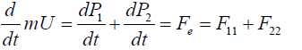
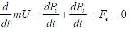
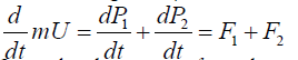
The center of mass of the system is a point r where the entire mass m=m1+m2 of the system can be thought to be concentrated. It is defined by the relation mr=m1r1+m2r2. The motion of this point is only determined by the effect of external forces since we have:
 (1)
(1)
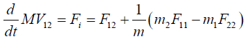
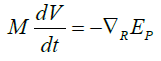
We can now study the motion of a second particle called the relative particle with a reduced mass M=m1m2/(m1 + m2). This single particle is located at the place occupied by either the first or the second particle depending on the choice of the rest position. The distance R is therefore R12=r1−r2 if the particle 2 is located at the origin of a reference frame or R21=r2−r1 if the particle 1 is now the origin of our reference frame. For each choice, we have an equation of motion:
 (2)
(2)
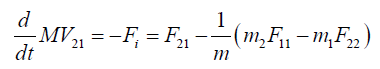 (3)
(3)
where the relative velocity V=dR/dt between the two reference frames is reciprocal since we have V12=−V21. It follows that the reciprocity V12=−V21 of the rest reference frame is indeed linked to the existence of Newton’s third law as shown in Figure 1 for the three possibilities. The reciprocity concept and Newton’s third law are two faces of the same coin.

Figure 1: The mutual force between two identical particles of mass m0 can depend on the choice of an origin for an isolated system.
Therefore, we cannot use the reciprocity of the reference frames in special relativity and at the same time state that Newton’s third law does not apply in special relativity.
When the external force is zero Fe=0, the system is isolated and the velocity of the center of mass is zero in the laboratory frame or it is a rectilinear uniform motion in another reference frame as stated by Newton’s first law:
 (4)
(4)
It follows that the velocity U=dr/dt and the kinetic energy EK=mU2/2 of the center of mass are constant or zero. Hence a failure of the third law would be a failure of momentum and energy conservation. If the external forces are zero and the internal force Fi=F12 is derivable from a potential function EP (R), the equation of motion for the reduced mass becomes:
 (5)
(5)
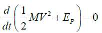
One can multiply both sides of the above equation by V, it follows
 (6)
(6)
-Therefore, we have conservation of the mechanical energy of an isolated system only when the internal forces are central and satisfy Newton’s third law for translation. The splitting between internal and external forces is independent of the nature of the force, and therefore, this partition must apply in all branches of Physics as shown in our review paper [15].
The existence of stimulated forces which do not satisfy Newton’s third law deserves special attention since it results from the above calculation that these forces induced inside matter can be used to do space propulsion. To propel a craft with an external force has also a great advantage for the human beings who will not be submitted to stress since this force is only applied to the center of mass of the whole space transportation system. The only question to be answered is how do we generate an external force?. Since the Lorentz force does not follow Newton’s third law, this force can be used for building a new advanced propulsion system.
The Lorentz force law and the stimulated force
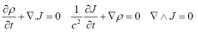
As stated in the introduction, there are two force laws of motion in electromagnetism. The most well-known is the Lorentz force law which leads to the Lorentz-Maxwell’s equation of motion
 (7)
(7)
where the Lorentz force FLij applied to the particle i is given by the formula:
FLij=qi(Ej+1/cUi∧Bj) (8)
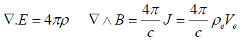
The electromagnetic field Ej, Bj is an external field produced by another charged particle j. We can make several remarks concerning the Lorentz force law above:
• The first remark concerns the fact we use the C. G. S. system of units which is still largely in use within the international scientific community and in universities, in particular by physicists dealing with plasma physics. Moreover, this system of units underlines the role played by the speed of light and allows a direct connection with the special relativity theory.
• The second one is to question the meaning of the velocity Ui of the charge qi that appears in Eq. 8. As pointed out by Assis [54], most textbooks do not state explicitly what the velocity Ui is relative to. Of course, according to the special theory of relativity, the velocity of the charge qi is the velocity defined with respect to an inertial reference frame. Therefore, this velocity will have different values in different inertial reference frames.
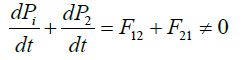
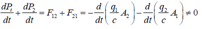
• The third remark concerns the well-known fact that the Lorentz forces do not satisfy Newton’s third law since we have FLij ≠−FLji. We will demonstrate again that this fact implies the existence of external forces that can perform work whose energy is provided by the medium. Therefore, to show the existence of external forces, we must consider the interaction between two moving charges with forces that violate Newton’s third law. Since the Lorentz forces exerted by freely moving charges upon one another are not equal and opposite in principle, it follows that a system consisting of pair of charged particles in relative motion can change the state of motion of their center of mass without external help.
Consider now two charged particles q1 and q2 moving with velocities U1 and U2 relative to a given reference frame. We stress that all the following calculations are done in this reference frame; therefore, no change of reference frame is implied in the discussion.
The charge q1 exerts on q2 a force F21=q2(E1+U2 ∧ B1/c) where E1 and B1 are the electric and magnetic fields produced by q1 at the position occupied by q2. Conversely, the charge q2 produces on q1 a force F12=q1(E2 + U1 ∧ B2/c). In general these two forces have different directions and magnitudes:
 (9)
(9)
The above equation can be written in a form often encountered in the literature, namely:
 (10)
(10)
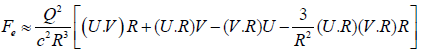
From this equation, one can deduce that field theory attributes momentum to the electromagnetic to allow a particle to interact only with fields at the position of the particle. It precludes the possibility of instantaneous particle interactions except as an approximation. Therefore, the interaction between the particles proceeds by a transfer of momentum from one particle to the field, then the field transports the momentum at light speed to the position of the second particle where it can be transferred from field to the other particle. However, this transfer cannot be symmetric since the above equation can be rewritten as follows:
 (11)
(11)
Fluid approach of the stimulated force
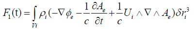
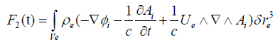
We will now give a fluid approach of the calculation of the stimulated force by taking into account the motion of positive and negative ions in motion with velocities Ui and Ue with respect to a reference frame located in the center of mass of the Milky Way, the potential solutions are given by the integrals:
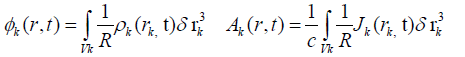 (12)
(12)
for k=e, i with the definition ` . We can neglect the retardation effect for charge distributions strongly localized in Vk. The two Lorentz forces between the fluids are calculated from the relations:
 (13)
(13)
 (14)
(14)
The equation of motion of the center of mass of the two fluids of mass m is given by the relation:
 (15)
(15)
Since the electrostatic forces between the two fluids derive from potential functions, we have the identity:
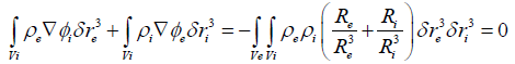 (16)
(16)
The above equation describes the mutual interaction between the positive and negative particles due tu the electrostatic forces which satisfy the Newton’s third law. Therefore, the reciprocity condition Re=−Ri implies that the total force applied to the center of mass is zero. Indeed each quantity Rk=r−rk in the double integration is calculated for rk fixed for rk fixed for r=rn with n≠k
There is no general agreement on the mechanism responsible for the force produced in the electrostatic pendulum that would be examined hereafter. Therefore, the above equation is fundamental to understand why ion wind or EHD propulsion cannot explain the motion of the pendulum when a high voltage is applied. As explained later, the ionization of air by thin nude wires produces plasma between the wires which prompted some authors to invoke the electrostatic forces and Newton’s third law to explain the rectilinear motion of the capacitor or the lifter.
On the contrary, the equations 16 where the charged particles of both the plasma and the copper wires are taken into account in the calculation forbid such a possibility. In fact, it is the magnetic force which produces the motion as shown above.
Indeed, the experiments described in the literature concerning ion and plasma propulsion has nothing to do with the pendulum or the lifter experiments discussed in this paper because the ion and plasma exhaust is quasi neutral in both cases. A special mechanism of neutralization is used to avoid a back motion due to space charge. Therefore, ion and plasma propulsion engines work as rocket engines obtaining thrust in accordance with Newton’s third law but for neutral bodies only.
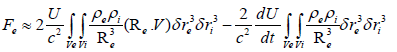
Using the continuity equation and the definition of the total derivative, the stimulated force Fe=F1+F2, after a few calculations, is given by the expression:
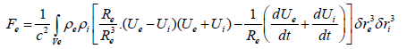 (17)
(17)
We can simplify the above expression by writing ` `
` and `
and `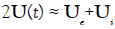 it follows:
 (18)
(18)
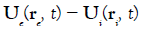
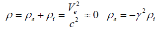
The stimulated force is a function of an absolute velocity U and its derivative which depend on the choice of a reference frame and a relative velocity V which is independent of this choice. We note that the magnitude of the stimulated force depends on the electron current density J=ρeV flowing in the reference frame where the positive ion fluid is at rest.
In the special relativity theory, we consider that Earth is an inertial reference frame where the velocity U and its derivative are zero. Consequently, no stimulated motion can be expected in this theory for a body at rest in this reference frame. Since Earth is moving through space, then the existence of rectilinear and rotational motions as discussed in several papers [15,33-53] is expected to be observed in the Earth’s reference frame.
For a point particle theory, the charge densities have for expression:
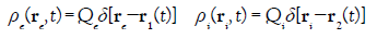 (19)
(19)
If we substitute the above relations in Equation 18, we get
 (20)
(20)
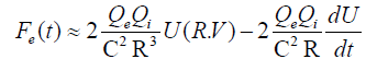
where R=r1−r2 is the distance between the space charges Qe and Qi. From a different point of view as demonstrated in our book [53], we get another expression for the stimulated force in a capacitor simulation:
 (21)
(21)
With the definitions Q=Qi=−Qe. In the above relation V=U2-U1 and U=U2 are respectively the relative and absolute velocities where we have assumed the condition V << U.
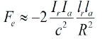
Whatever the correct expression for the force, what we need is an estimation of the magnitude of the force, neglecting the acceleration term in Eq.20, then the force has for maximum magnitude:
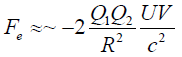 (22)
(22)
We can always write the definitions Q1=−C1Vb and Q2=C2Vb where C1 and C2 are real or virtual capacities related to the experimental setup and Vb is the voltage of an external battery. Taking into account these definitions in the preceding equation, we have:
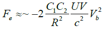 (23)
(23)
Therefore, the stimulated force depends on the square of the applied voltage as shown by several experiments [10,30,31].
We can also write formula 22 in another form. If nk is the density of the free charges present in the volume Vol=Sklk, then the current is given by the expression Ik=nk qSkUk where Uk is either the relative or the absolute speed of the charge Qk=Nk q and q is now the charge of the electron. We can rewrite the above formula in a simple form:
 (24)
(24)
The charges Q1 and Q2 have opposite sign; therefore, the force is negative. The currents Ia and Ir are respectively the absolute and relative currents. The above equation demonstrates that the presence of two currents is a necessary condition to observe the motion of a capacitor charged with a high voltage. The conduction current Ir can be provided by the ionization of a plasma between the plates of the capacitor or by the presence of a leakage current in a dielectric. In the vacuum or in an insulating medium such as oil, the conduction current is almost zero but this is not the case of the convection current inside the material as we shall see hereafter. By comparison, the magnetic force between two parallel wires of length l is given by the expression:
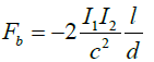 (25)
(25)
The preceding formula can be applied to the two parallel wires of the pendulum where a repulsive force exists since I1=−I2 but this force is compensated by the presence of the insulating rod between the two balls.
If the ion current I is due to the applied electric field E then we can calculate the electrostatic force as given in the literature to explain the motion of the capacitor
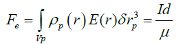 (26)
(26)
Where μ is the ionic mobility. We must point out that all the authors made this calculation as if there is only one kind of charged particles which defines the current I while the formula 24 takes into account two currents. We recall that the conduction current definition is I=nqSVd where Vd is the drift velocity of one kind of charged particles given by the formula Vd=μE, this is the case in a conductor but not in a plasma. The formula 26 cannot be used to explain the stimulated motion of capacitors as we shall see hereafter. However, the formula 26 explains why the presence of plasma between the plates of a capacitor increases the magnitude of the force for two reasons: the magnitude of the current I in plasma is far greater than the leakage current in a dielectric. The second reason, the ion mobility in the plasma μp=2.1 10−4 × m2/(Vs) is about 18 times smaller than the copper mobility μc=4.4 10−3 m2/(V s).
Definition of the current density in a material
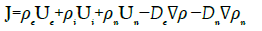
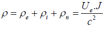
As stated in this paper, the stimulated force results from the violation of the Newton’s third law by the magnetic force Fm=J ∧ B/c. To evaluate the stimulated force produced by the motion of a plasma or a metal in vacuum necessitates to take into account a full set of transport equations as done in our book [54] but applied this time to a three fluids, namely: the positive and negative ions and the neutral molecules in the plasma or to the positive atom lattice, the negative electron fluid and a new negative fluid which results from the injection of new electrons in the metal or the motion of electrons due to the absolute motion of these electrons in vacuum.
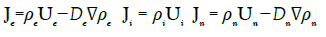
Seaver [55] developed a charge flux equation for any charged species in a general material (solid, liquid or gas). In the derivation, he assumed that magnetic field effects could be ignored which is not totally correct if we have to take into account the magnetic force. The density current given by Seaver for the”ith” species is:
Ji=ρiVi+σiE−Di∇ρi−ρiGi∇Ti (27)
The current density Ji at any point in the material depends on the charge density ρi, the electrical conductivity σi, the electric field E and the diffusion Di and the temperature Ti at that point. For liquids and gases the material might have a bulk material drift velocity Vi. Seaver considers the case of a stationary metal and assumes that this material drift is zero. To simplify our analysis, we assume that ∇Te=∇Ti=0 and rewrite his equation in a more general form taking into account the conditions σi=0 and ∇ρi=0 which are satisfied in a metal.
 (28)
(28)
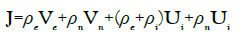
The total densities of current and charge become:
 (29)
(29)
 (30)
(30)
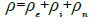
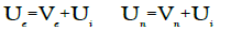
Where all the velocities Uk are now absolute velocities defined with respect to a given reference frame. In this formulation, we take into account a new quantity ρn<0 which is a density of charges that results from injection of charges in the metal generated by an external source or an unbalanced space charge due to the motion of the metal. Let us write the definitions:
 (31)
(31)
For the time being, we drop the diffusion terms for the discussion that will follow, and then we have:
 (32)
(32)
The density of current J=ρeVe=σeE is the conduction current defines in the Ohm’s law with the relation σe=−μeρe for ρe<0. The second term is also conduction current as studied by Seaver. The two last terms are convection currents taken to be zero in the laboratory frame as done in the Seaver’s analysis.
The analysis by Seaver [56] concerning the motion of free electrons in an infinite wire far from to any conducting metal is in contradiction with other analysis [57,58] where the magnetic field due to the current itself produces a pinch effect of the electrons which must be taken into account. Therefore, the usual Ohm’s law must be replaced by the expression J=ρeVe=σe(E+Ve ∧B). When the steady state is reached, the electrons are concentrated towards the axis of the wire leaving a layer of positive charges at the surface. This is just the opposite case in the analysis presented by Seaver where the excess of free electrons migrates towards the surface of the wire with no excess of electrons left on the axis of the wire. Taking into account the Hall effect has a consequence concerning the neutrality of the conductor, a fact which is know from a long time [57,58]. For a steady current, we have:
 (33)
(33)
In the laboratory frame where Ui=0 and assuming ρn=0, we have:
 (34)
(34)
Substituting the preceding equation in Equation 32 gives:
 (35)
(35)
Since the quantity V2/c2 has a very small value, we can assume that the metal is neutral. Now if we have Ui=0 and ρn≠0, for the same calculation, we get:
 (36)
(36)
For a conduction current 1.5 mA in our pendulum experiment, we get Ve/c ≈ 10−19 while we have Ue/c ≈ 1.2 10−3 for the convection current.
In an interesting paper, Seaver [56] discuss the conditions that a metal must fulfill to be an Ohmic conductor. We recall that the field form of Ohm’s law is defined in a metal by the relation J=σE where σ is the electrical conductivity of the metal, J is the current density flowing through the conductor and E is the electric field produced by an external battery. The field form of Ohm’s law can be used to derive the circuit form Vb=RI of Ohm’s law. However, the field form is often used to investigate what happens inside an ohmic conductor. Seaver does a thought experiment which consists to inject instantaneously and in a uniform manner new electrons with a density ρn along the metallic wire which is not possible without the presence of a diffusion current. However, Seaver pointed out an argument that has escaped most authors when dealing with the motion of the current in a conductor. Indeed, all the authors state that the intensity I of a current in a conductor is given by the simple formula I=nqSV where n is the number density of the free electrons already present in the conductor and V their uniform speed inside the metallic wire. They assume that all electrons move at the same time as a solid as soon as an external electric field E has been applied to the two extremities of the wire when a battery has been connected.
In fact in the closed electric circuit, there is is usually a switch and electrodes which are directly connected to the wire in the circuit. When the switch is turn on, two things happen: an electromagnetic wave is produced and propagates at the speed of light around the wire and penetrates the wire radially to induce the slow uniform motion of the electrons and other electrons are injected with a density np in the wire by the battery. This input of new electrons modifies the electron number density ne and therefore the conductivity σe of the metal. There is an additional current In that must be taken into account in the analysis. It is important to point out that when we measure an ohmic current in a steady state with a current probe, one cannot discriminate between the two conduction currents in Equation 31.
Moreover, if a probe current cannot measure the convection currents, it does not mean that these currents do not exist.
Seaver demonstrates that the Ohm’s law is weakly modified if np << n which implies that the current In is small. To verify this condition, the drift speed must be below 1% of the average thermal speed in the conductor. This leads him to evaluate the maximum electron number density in copper to be 3 1017 electrons/m3 and a maximum radial electric field Er = 2.7 106 V /m for a 2 mm diameter wire.
The neutrality of a material is an important factor with regards to the production of a stimulated force as shown by equation 32 and equation 36. To understand the difference between the generation of the stimulated force in a plasma or in a conductor when free charges are present or injected by a battery, one have to study the behavior of the free electrons which move with a relative current with respect to the opposite charged particles fixed (conductor) or not (plasma) considered to be at rest in a given reference frame. In a plasma, we used the concept of Debye length λd=(kbT/4π nq2)1/2 in C.G.S units. This quantity is used to calculate the screening potential function for a charge Q placed at the center of the Debye sphere:
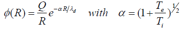 (37)
(37)
On the contrary, Arbab [59,60] examines the problem with a wave approach with the set of equations:
 (38)
(38)
form a system of equations which can be uncoupled in two wave equations:
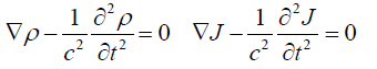 (39)
(39)
not knowing that we have introduced these conditions in our book [53]. The solution is well known:
 (40)
(40)
with the definitions λ1=c τ=cs/σ where τ is a relaxation time constant. For silver, we get λd= 4 10−10 m and τ = 1.4 10−19 s
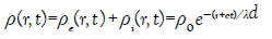
In a conductor, we are more interested by the time behavior of the charge density ρ(t). Given any initial distribution ρ(0), the time evolution of ρ is given by the equation:
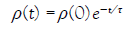 (41)
(41)
Once the unpaired charge density has decayed to zero in a conductor, it will remain zero. The above formula explains the reason why no stimulated force is observed in a conductor if no free currents are deliberately sent into it. Indeed, any free charge distribution ρ=ρe+ρi→0 will decay with a decay time τ ≈ 10−19 s in a good metallic conductor. Thanks to the small τ no metallic object can spontaneously move in our environment. Therefore, the electric field E and the relative velocity Ve are zero in a neutral conductor if there is no DC source connected to the conductor.
Ohanian [61] published an interesting paper with a critical review about the relaxation time constant definition. We can also quote the paper by Seaver [62] who derived an equation for charge decay valid in both conductors and insulators:
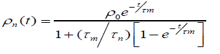 (42)
(42)
where τm=s/σm is the material time constant and the perturbation time constant τn=s/μρ0 defined by the initial perturbation charge.
The formulation of Equation 20 or Equation 21 indicates that the force depends on the direction of the Earth motion through space. Therefore, a change of the force must be observed if measurements are performed over a long period of time which is the case as shown by several authors.
Brown experimental work
T.T. Brown was the first author to speak of the effect ignoring the work of Trouton- Noble in 1903 when he wrote:”In subsequent years, from 1930 to 1955, critical experiments were performed at the Naval Research Laboratory, Washington, DC.; the Randall-Morgan Laboratory of Physics, University of Penna., Philadelphia; at a field station in Zanesvill, Ohio, and two field stations in Southern California, of the torque was measured continuously day and night for many years. Large magnitude variations were consistently observed under carefully controlled conditions of constant voltage, temperature, under oil, in magnetic and electrostatic shields, not only underground but at various elevations.
These variations, recorded automatically on tape, were statistically processed and several significant facts were revealed. There were pronounced correlations with mean solar time, sideral time and lunar hour angle. This seemed to prove beyond a doubt that the thrust of “gravitors” varied with time in a way that related to solar and lunar tides and sideral correlation of unknown origin. These automatic records, acquired in so many different locations over such a long period of time, appear to indicate that the electrogravitic coupling is subject to an extraterrestrial factor, possibly related to the universal gravitational potential or some other unidentified cosmic variable.”
Saxl experimental work
Saxl and Allen [12,13] worked with an electrically charged torque pendulum. Saxl used high voltage in the range of 5 kV on his very massive torque pendulum. The changes in period of oscillation measurements with solar or lunar eclipses, showed great sensitivity to the shielding effects of gravity during an alignment of astronomical bodies, helping to corroborate Brown’s observation. The pendulum Saxl used was over 100 kg in mass. Most interesting were the “unexpected phenomena” which Saxl reported in his Nature paper. The positively charge pendulum had the longest period of oscillation compared to the negatively charged or grounded pendulum. Diurnal and seasonal variations were found in the effect of voltage on the pendulum, with the most pronounced occurring during a solar or lunar eclipse.
Cornille-Naudin experimental work
This effect can be tested more easily in the case of rotational motion of parallel-plate capacitor such as in the Trouton-Noble experiment. The experiments were performed in a laboratory located nearby Paris. These experiments were repeated dozens of time with similar test devices and different types of power supplies over a three-year period. The same types of results invariably came out. We shall only present here the exploratory side of this research so as to encourage the replication of the TN experiment by academia and other members of the scientific community.
Our basic experimental set up was built along the following lines: a parallel-plate capaci- tor 500 pF was manufactured by fixing together two conducting aluminum foils 190 * 150 mm 0, 33 mm thick on either side of a transparent, non-shielded insulating plate of Plexiglas 250 * 210 mm, 2 mm thick, ∈r=4. This capacitor was suspended from the ceiling of by a thin nylon thread l=1.5 m. A hole, diameter 0.5 mm lined up with the center of mass of the capacitor, perforated the plate of Plexiglas 10 mm away from the top edge. The thread was attached to the capacitor by means of a node, and fixed to the ceiling so as to reduce frictional forces. The suspended capacitor could rotate freely either side on its vertical axis, without being significantly affected in its rotational motion by the mechanical counter torque originating from the suspending fibber. The wires feeding the capacitor with high voltage were coated. Two variants of this basic device were used, thus enabling us to obtain three different manifestations of what seems to be the same underlying effect.
Test 1: The wires feeding the capacitor were connected to the center of the plates. Our first qualitative experimental results were obtained back in 1996 and 1997 with a Wimshurst generator. This type of generator is known to produce high voltage 70 kV and very low currents ≈ μA. Any time the experiment was repeated, our capacitors sought a position of stable equilibrium in the East-West direction, where they remained “locked” until discharged. The total torque was subsequently demonstrated to be negligible for a symmetric and homogeneous distribution of charges over the plates, provided that the voltage used in the experiment were low. The observed effect was also demonstrated to be extremely weak if the charges distributed over the plates were the only charges involved in the calculation of the effect. Indeed, it appears that the structure of space charges inside the plates and the polarization of the dielectric material can significantly affect the generation of the observable torque when the two following criteria are met: the applied voltage must be higher than 25kV and a small leakage current must exist inside the dielectric material.
Test 2: We employed a Wimshurst generator. The phenomenon of electrical influence was chosen as the primary mechanism for feeding the capacitor. A coated electrical wire, top bare, neighbored a rotating distributor, these two elements being distant from each other. The distributor was a flat, disc-shaped device attached to the suspending fibber, enabling us to benefit from the inertia effect. The capacitor would gain momentum whence charged, and discharged when it reached its calculated, stable position of equilibrium. We thus observed a continuous rotation of ≈ 10 rpm.
Test 3: Quantitative experimental results were obtained with a shielded, grounded bipo- lar power supply, two Glassman HT8 HV generators. With such generators, voltage and potential differences were controlled, monitored and reached a maximum value of 50kV. Currents could be monitored with an accuracy of 1%. Test 3 consisted in a slightly modified version of test 2, where the segmented distributor was replaced by a continuous distributor. A continuous rotation was observed as soon as the HV power is turn on. When the experiment was started, the plates of the capacitor were lined up with the NNW − SSE direction θ = −45◦. The West-hand plate was negatively charged while the East-hand plate was positively charged. A “trigger effect” was observed when the potential difference reached a critical value of ≈ 25 kV. The capacitor was then set into motion clockwise. The first half-turn was completed in 13 s or 2, 3 rpm while the second half turn in 9 s or 3, 3 rpm. During the cruise regime, i.e., before the rotation of the capacitor was curbed and inhibited by the mechanical counter torque originating from the torsion fibber, the capacitor was found to rotate at 6 rpm.
We discovered that the direction of rotation of the suspended, parallel-plate capacitor had changed between April-June and early September 1998. To our extreme puzzlement, a new change in the direction of rotation was observed “live” on September 23, 1998, i.e., the day of the autumnal equinox. The “ecliptic crossover” is physically impossible to perform since the Earth never crosses the plan its defines with the Sun. However, we did observe that the direction of the rotational motion of the suspended parallel-plate capacitor would change when the Earth crossed its equinoctial positions. However surprising, this experimental result must be compared to Allais’ statistical analysis of Miller’s chronological series. Among others, Allais demonstrated that Miller’s optical an ether drift observations would reach their climax when the Earth crosses its equinoctial positions [69] in particular. All these experimental results were published in an international conference STAIF 2000 [41].
We reviewed in this paper, over a 149 years period of time, many experiments done throughout the world showing the rectilinear and rotational motion of material objects when they are submitted to external voltages. These experiments have been totally ignored by the scientific community except for the last 20 years where the lifters experiments and theirs publications on web sites finally raise the interest of some physicists. May be, we can explain this lack of interest by the fact that no credible explanation was given to justify these motions.
Finally, we explain the reasons why these motions are possible within classical physics by noting that the Lorentz’s force violates Newton’s third law due to the magnetic force. All the experiments done with capacitors supplied with high-voltage and low-current or high-current and low-voltage prove the existence of stimulated forces violating Newton’s third law. The rectilinear and rotational motion has been observed for capacitors moving in vacuum or oil and also for plate capacitors with a dielectric where no ionization is possible. Therefore, the experimental evidence concerning these forces cannot anymore be denied and should lead to important technical applications concerning space propulsion in the near future and also a better comprehension of physics.
The author wishes to thank Dr. Loic Lamballais for a financial support for the publication of this paper.
Citation: Cornille P (2020) A Review on Electromagnetic Propulsion by Stimulated Forces. J Aeronaut Aerospace Eng. 9:221. doi: 10.35248/2168-9792.20.9.221.
Received: 11-Apr-2020 Accepted: 25-May-2020 Published: 01-Jun-2020 , DOI: 10.35248/2168-9792.20.9.221
Copyright: © 2020 Cornille P. This is an open-access article distributed under the term of the Creative Commons Attribution License, which permits unrestricted use, distribution, and reproduction in any medium, provided the original work is properly cited.