Advances in Automobile Engineering
Open Access
ISSN: 2167-7670
ISSN: 2167-7670
Research Article - (2023)Volume 12, Issue 4
Reducing engine emissions through increased efficiency of engine is crucial to lessen the adverse effects of ongoing global warming. An effective design of cooling systems has a proven effect on the enhancement of cooling systems. Industrial perspectives have shifted from traditional product development methodologies to rapid prototyping approaches as a result of rapid prototyping and manufacturing techniques. The aim of this study is to design, analyze and optimize the radiator water pump impeller manufactured through fused deposition modelling, by using ABS. Several geometries of different designs of automobile cooling system water pump impellers were designed and analyzed using solidworks and ANSYS. One conventional and two optimized designs were finalized based on cost, weight, functionality, and manufacturability. The experimental investigation was also carried out for the validation of results at different RPMs. Optimized model C had an 80% improved flow rate model B had a 50% improved flowrate as compared to the conventional design.
Additive manufacturing; Fused deposition modeling; Cooling system; Impeller optimization, 3D printing
Modern reciprocating internal combustion engines having low emissions are being developed in response to new Euro requirements that are implemented in Europe and the US. Additionally, the trend is that trailer weight is rising, which makes customers seek high power, high performance, and lower fuel usage engines in addition to high fuel rates [1]. An incredible amount of heat will be produced when fuel is combusted inside an internal combustion engine in a vehicle. It is possible for the temperature of the burning gas to reach 2200°C or higher while the air-fuel mixture is being burned in the engine cylinders [2-4]. In order for the engine to function properly, the heat that is generated is converted into kinetic energy through the pistons, connecting rod, as well as other mechanical components. Nevertheless, not all of the heat is capable of being converted into usable mechanical power. The amount of energy that can be transformed into mechanical power from the energy that is created by combustion is approximately one third. In the meantime, another third of the energy is lost as heat from the exhaust, and the remaining energy is redistributed by the cooling system [5-7]. 35% to 45% of efficiency would be increased with effective cooling system of any IC engine [8]. This research would have a direct impact on conventional IC engines cars generally in developing countries and particularly the 6.6 million LTV registered in Pakistan in term of improving the efficiency and reduction of pollution [9].
A normal four cylinder car travelling at 50 miles per hour on the highway will generate 4000 controlled explosions inside the engine every minute as the fuel is burned by the spark plugs in every cylinder to move the car forward. It goes without saying that these detonations generate an incredible quantity of heat and, if uncontrolled, will quickly kill the engine. The task of the cooling system is to regulate these highly elevated temperatures [10]. In 1920’s the cooling systems centered in the model T were not all that different from the cooling systems in use today. The elementary cooling system remains comprises of fluid coolant being cycled across inside the engine and then transferred to the radiator which is to be cooled by the stream of air flowing through the front of the grill of the car. It has become massively more dependable and efficient at performing its job. Whether the air outside is 110°F as well as 10° below zero, recent cooling system must be reliable enough to retain the engine at a steady temperature. Fuel economy will be negatively impacted and emissions will increase if the operating temperature is too low [11]. The engine will get destructed itself if the temperature is permitted to remain too high for an extended period of time.
In automobiles four types of water based cooling systems are found namely pump circulation system, impeller circulation system, thermo siphon system and pressurized cooling system [12,13]. In thermo siphon system the variation in temperature (i.e., variation in densities) of the water in this cooling system is what causes the water to circulate [14]. Consequently, with this system a pump is not necessary; instead, water is circulated solely due to a difference in density. In pump circulation system, a pump is used to create water circulation. V-belts attached to the engine crank output shaft power this pump [15]. In impeller circulation compared to the thermosiphon cooling system, this represents an improvement. Everything about it is the same, with the exception of a small impeller unit that is powered by the engine on its own to speed up water circulation. In pressurized cooling system compared to the cooling pump circulation system; this is an upgrade [16]. This system uses a unique radiator cap with a pressure valve as well as vacuum valve that are spring loaded [17]. The pump impeller was the other parameter that was altered by using several simulations with varying numbers of impeller blades. By doing this, the impact of changing the mass flow rate, outlet velocity, inlet velocity, and outlet pressure. As a result of increasing the sum of blades, angle optimization flow rate would be increased [18].
There are three major types of pump impellers which are used in cooling system of any automobiles namely open impeller, semi open impeller and cutter impeller in some specific case. In open impeller vanes have no protective shroud and are open on both sides [19]. They are often employed in less expensive and smaller pumps that aren't put under a bulk of stress because they typically lack assistance from either side, making them weaker [20]. In semi open impeller the back-wall shroud strengthens the vanes mechanically while the other side remains open. They are appropriate for pumps that are medium sized with a small amount of lenient particles because, they fall between closed and open impellers in regards of efficiency and NPSHr [21]. While in closed impeller maximum strength is provided, which is encased at the back and front. They offer a more operative flow and have a little NPSHr requirement. Though, because they depend on close-clearance worn rings to lessen axial loads and support efficiency, they have a more complex and expensive design [22].
Researchers looked into how the centrifugal pumps hydraulic performance was impacted by the blade wrap angle and blade exit angle [23,24]. The centrifugal pump's specific speed and the real optimum design experience are the key factors that influence the choice of blade exit angle and blade wrap angle [25]. Too much of a blade wrap angle results in a huge impeller friction area, which is undesirable for increasing efficiency. The impeller cannot properly control the flow of water and cannot function steadily if the angle of the blade wrap is too small. A reasonable value for the blade exit angle could significantly enhance the hydraulic capabilities of the centrifugal pump [26].
Today, original impeller and optimized designs for water pumps are frequently created with the aid of numerical models, practical tests, and the hiring of external consultants [27]. When several design parameters are considered and the complete 3D-domain is simulated and estimated, computations are expensive and need numerous flow field evaluations [28]. Due to extensive CFD research and testing, there is currently a lag between how the system functions as well as what the radiator pump will deliver [29]. In order to forecast how the pump would behave based on pump geometry and operating conditions, a preliminary design tool is required. This tool can provide an initial result that can then be fine-tuned using CFD and experimental tests. This will speed up the development of newer engine cooling systems also boost the developer's understanding of how various modifications in geometry effect radiator pump performance [30].
The objective of this work is to develop an automobile cooling system water pump impeller through the fused deposition modeling by the ABS robust material. Comparative analysis also carried out between the conventional and optimized impellers and to reduce the process time and material minimization.
ABS, also well-known as acrylonitrile butadiene styrene, is an opaque engineering thermoplastic that is frequently employed in pipefittings, lego toys, electronic housings, and other items. Acrylonitrile Butadiene Styrene, often known as ABS, is a standard thermoplastic polymer that is classically utilized for injection molding practices. However, it is now being employed in rapid prototyping techniques like as 3D printing and additive manufacturing [31]. Owing to its ease of manufacture and low cost of use by plastic producers, this engineering plastic is popular. Even more, its intrinsic benefits of affordability as well as machinability do not interfere with the desirable qualities of the ABS material. The key characteristics that make ABS suitable for current application includes, impact resistance, structural strength and stiffness, chemical resistance, outstanding high and low temperature performance, excessive electrical insulation properties, easy to glue and paint. Li and Shimizu describe the melting point of ABS polymers is around 200°C (392°F). It is intense, hard, stiff, very dimensionally stable, and chemically resistant. ABS is the best material to use where exceptional surface quality, colorfastness, and shine are required. A two-phase polymer mixture is ABS.
The radiator water pump impeller was scanned in order to obtain the 3D conventional model's precise surface dimensions. National Institute of Design and Analysis (NIDA) Lahore performed 3D model scanning in order to transform the conventional model into a 3D solidworks model for more impeller research. Free form surfaces, gradually shifting profiles, and curved component shapes can all be digitally captured with a 3D scanner. To obtain information about cluster spots, the profile of these components is laser scanned. The data is then processed using specialized reverse engineering software to produce a viable digital model. The program provides a method for precisely surfacing 3D digital models enabling reverse engineering, product development, fast prototyping, and analysis from 3D scan data using polygon meshes (Figure 1).

Figure 1: Scanned 3D impeller.
After the CAD cleanup of the scanned 3D model, we got the full access to the conventional impeller, which are shown, in the Figure 1. Solidworks 2021R software used for the 3D modeling and further optimization and analysis was done on solidworks 2021 software.
Conventional impeller was optimized to two more different models having 7.5° and 15° blade surface angle respectively. Two planes were drawn on both side of the impeller blade and sketch drawn on the front side of both impeller with 7.5° and 100 mm curve radius for 7.5° degree optimized model shown in Figure 2. As well as for 15° degree optimized model the curve angle was 15° and the curve radius was 50 mm is shown in Figure 3. Cut lofted methods were used to draw the hyperbola on the surface of impeller blade. The sketches were only cut lofted at the front side of impellers. Behind surface was same as the conventional impeller.

Figure 2: Optimized 7.5° impeller.

Figure 3: Optimized 15° impeller.
Conducting a mesh independence research is one way to find out if the simulation findings were independent of a specific mesh. By running numerous simulations with different mesh resolutions and checking to see whether the results change. Because to the basic mechanics of the CFD simulations as well as the underlying mathematics, this kind of inquiry is essential. To find out if the outcomes depend on the mesh density, a researcher can conduct a mesh independence (or grid independence) research. I completed a mesh independence investigation between 0.1 m and 0.007 m for the improvement of conventional model outcomes. The mesh size was finalized on the bases of results outcomes that were 0.01 m and type of meshing was tetrahedral. Following are the mesh independence study steps. Use the fewest, most sensible number of elements to create a mesh, and then examine the model. Create a new mesh with a tighter element distribution, analyzed it again, and contrast the outcomes with the mesh you previously created. Continue re-analyzing the model and increasing its mesh density until the outcomes converge well (Figure 4).

Figure 4: Mesh quality graph.
Unstructured tetrahedral modelling for the radiators pump impeller flowrate process was represented using ANSYS Fluent. Keeping the model independent from the grid allowed for numerical simulations depending on nine different networks to be tested for potential computation time savings. The volume flow rate performance increases of nine different masks. At mesh independence testing, the number of cells of 1.74, 2.12, 2.60, 3.19, 3.75, 7.28, 16.90, 16.95, 16.98 LACs of tetrahedral meshes were examined for speed at 3000 RPM. The relative error between two consecutive stitches was lower (5%), demonstrating that the CFD findings are not affected by mesh size. The computational grid model and cell numbers in connection to product quality are depicted.
The numerical simulations using the shear stress turbulence k-omega two equations model in CFD fluids, such as the SST K-omega model, are best suited for increased volume flow rates. There are numerous uses for the SST k-omega turbulence model, a two equation eddy-viscosity model. It is a hybrid model that combines the k-epsilon and k-omega Wilcox models. The Wilcox model close to the wall as well as the k-epsilon model inside the free stream is both actuated by the combination function F1. The SST K-omega turbulence model equations are listed below.
SST K-omega governing equations
Turbulence kinetic energy

Specific dissipation rate

F1 blending function

Note: F1=1 inside the boundary layer and 0 in the free stream

Kinematic eddy viscosity
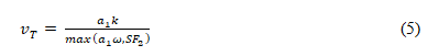
F2 Second blending function
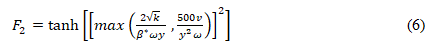
Pk (Production limiter)
CFD parameters
Following below parameters were used to simulate the conventional impeller and optimized impeller from 500 RPM to 3000 RPM respectively (Table 1).
| CFD parameters | Conditions | Ranges |
|---|---|---|
| Inlet | For the inlet, the rotational speed boundary conditions have been employed. | 500 RPM to 3000 RPM |
| Inlet | Pressure at the inlet of the impeller | 1 ATM |
| Water inlet temperature | 358 K | |
| Turbulent intensity | 5% | |
| Inlet diameter | 12 mm | |
| Outlet | For outflow, velocity outlet boundary conditions have been employed. | |
| Turbulent intensity | 5% | |
| The walls of impeller | The standard walls function | |
| Terms of convergence: Continuity | 10-8 |
Table 1: CFD parameters.
Following the theoretical study, experimental work was conducted to validate the theoretical work. For the purpose of validating the results, an experimental setup was designed to test conventional and improved impellers. The following components make up the experimental setup: Water pump, water tank, flow meter, valve, tachometer, stop watch, speed regulator.
The SHF (m) centrifugal pump is constructed using the centrifugal force design principle. It includes a fast-rotating impeller blade that really can propel water into rotation and pump it out for transportation purposes. This centrifugal pump has a long shaft motor and is a horizontal multi-stage non-self-priming multistage centrifugal pump. The compact design enables the pump to have a small dimension and either an axial or radial exit. It is small, energy-efficient, sealed, and simple to maintain.
Pump performance range
• Flow: 24.50 m/h
• Head: 140.0 m
• Suction head up to 7.0 m
• Liquid temperature up to +40.0
• Ambient temperature up to +40.0
• Working pressure: 5.0 bar
• pH: 6.50 to 8.50
Water was stored in water tanks for usage in a variety of processes, including food preparation, chemical production, fire control, agricultural farming, drinking water, irrigated agriculture, and agricultural farming for both plants and livestock. In this research project, a 30 liters tank was used as a water storage container. Water pump and tank were connected by the pipeline. In order to determine how much liquid, gas, or vapor is travelling through a pipe or conduit, a device called a flow meter (also known as a flow sensor) monitors linear, non-linear, mass, or volumetric flow rates. Water valves control the flow as well as temperature of water in plumbing fixtures and pipes. When correctly fitted and functioning, the valves maintain steady flow and volume. Brass, plastic, stainless steel, bronze, cast iron, and galvanized pipe are used for water valves.
The portable tachometer monitors in two ways: Optically, and thus contact-free, or mechanically via a variety of adapters. A stopwatch is utilized to determine the duration of an event. The precision and accuracy with which it measures the time of an event distinguishes this type of watch. It operates by pushing a start button and a stop button. Speed control systems enable simple motor speed setting and adjustment. The speed control system's motor will either be a brushless DC motor or even a conventional AC motor. In this investigation, an AC motor pump is utilized to test impellers. In this instance, a 2000 W speed regulator was employed to control the speed (Figure 5).
Experimental setup:

Figure 5: Experimental schematic.
Conventional impeller
Simulation results: The results for the conventional radiator water pump impeller application are shown Figure 6, the maximum volume flow rate is at speed of 3000 RPM, which is 300.8479309 cm3/s and the minimum volume rate is at speed of 500 RPM which is 108.7899807 cm3/s at the outlet of conventional impeller. It should be noted that maximum volume flow rate is on the outlet of the impeller casing and should increase from 500 RPM to 3000 RPM respectively.

Figure 6: Conventional impeller simulation at 3000 RPM.
The results for the radiator water pump optimized 7.5° impeller application are shown in Figure 7, the maximum volume flow rate is at speed of 3000 RPM, which is 455.86 cm3/s and the minimum volume rate is at speed of 500 RPM which is 112.09 cm3/s at the outlet of optimized 7.5° impeller. It should be noted that maximum volume flow rate is on the outlet of the impeller casing and should increase from 500 RPM to 3000 RPM respectively.

Figure 7: Optimized 7.5° impeller simulation at 3000 RPM.
The results for the radiator water pump optimized 15° impeller application are shown in Figure 8, the maximum volume flow rate is at speed of 3000 RPM, which is 561.471 cm3/s and the minimum volume rate is at speed of 500 RPM which is 112.26 cm3/s at the outlet of optimized 15° impeller. It should be noted that maximum volume flow rate is on the outlet of the impeller casing and should increase from 500 RPM to 3000 RPM respectively (Figure 9).

Figure 8: Optimized 15° impeller simulation at 3000 RPM.

Figure 9: Theoretical graph of all models.
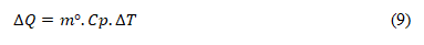
Figure 10 depicts the theoretical comparative analysis of speed of impeller and volumetric flowrate for optimized 7.5° impeller, optimized 15° impeller and conventional impeller. The maximum flowrates achieved at elevated RPM of 3000 for optimized 7.5° impeller, optimized 15° impeller and conventional impeller were 455.88 cm3/s, 561.47 cm3/s and 300.84 cm3/s, respectively. The comparison shows that optimized 15° impeller provides higher flow-rate while comparing it with 7.5° optimized impeller as well as conventional impeller. The relationship between volumetric flow-rate and heat transfer rate of radiator has been given in an expression below;
The expression above shows a direct relationship between heat transfer as well as mass flowrate provided by impeller. Moreover, enhanced mass flowrate for 15° optimized impeller will increase more heat transfer rate that may leads towards higher working efficiency of radiator in comparison to 7.5° optimized impeller as well as conventional impeller. However, heat transfer rate as well as working efficiency will change our research direction or domain so the quantification of these parameters was out of the scope.
Experimental results
The conventional impeller was run for 470.53 seconds experimentally, gradually increasing speed of impeller from 500 RPM to 3000 RPM, and decreasing the time to measure volumetric flowrate. Time was measured by using digital stopwatch; however, volume was measured through flowmeter. Figure 10 depicts that there was a direct relationship between volumetric flowrate and time elapsed.
The optimized 7.5° impeller was run for 407.25 to 27.15 seconds experimentally, gradually increasing speed of impeller from 500 RPM to 3000 RPM, to measure volumetric flowrate. Time was measured by using digital stopwatch; however, volume was measured through flowmeter. Figure 10 depicts that there was a direct relationship between volumetric flowrate and time elapsed.
The optimized 15° impeller was run for 404.39 to 21.10 seconds experimentally, gradually increasing speed of impeller from 500 RPM to 3000 RPM, to measure volumetric flowrate. Time was measured by using digital stopwatch; however, volume was measured through flowmeter. Figure 10 depicts that there was a direct relationship between volumetric flowrate and time elapsed.

Figure 10: Experimental graph of all models.
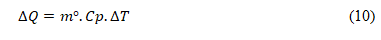
Figure 10 depicts the experimental comparative analysis of speed of impeller and volumetric flowrate for optimized 7.5° impeller, optimized 15° impeller and conventional impeller. The maximum flowrates achieved at elevated RPM of 3000 for optimized 7.5° impeller, optimized 15° impeller and conventional impeller were 368.32 cm3/s, 473.93 cm3/s and 213.31 cm3/s, respectively. The comparison shows that optimized 15° impeller provides higher flowrate while comparing it with 7.5° optimized impeller as well as conventional impeller. The relationship between volumetric flowrate and heat transfer rate of radiator has been given in an expression below;
The expression above shows a direct relationship between heat transfer as well as mass flowrate provided by impeller. Moreover, enhanced mass flowrate for 15° optimized impeller will increase more heat transfer rate that may leads towards higher working efficiency of radiator in comparison to 7.5° optimized impeller as well as conventional impeller. However, heat transfer rate as well as working efficiency will change our working domain so their quantification was out of the scope.
Comparative study
Figure 11 demonstrated the conventional impeller theoretical and experimental comparative study graphical representation. Theoretical volume flow rates are better as compared to experimental results due to some systematic errors as well as human errors. The volume flow rate gap between the theoretical and experimental is about to 70 cm3/s to 80 cm3/s from 500 RPM to 3000 RPM respectively.

Figure 11: Conventional impeller comparative graph.
Figure 12 demonstrated the optimized 7.5° impeller theoretical and experimental comparative study graphical representation. Theoretical volume flow rates are better as compared to experimental results due to some systematic errors as well as human errors. The volume flow rate gap between the theoretical and experimental is about to 50 cm3/s to 60 cm3/s from 500 RPM to 3000 RPM respectively.

Figure 12: Optimized 15° impeller comparative graph.
Figure 13 demonstrated the optimized 15° impeller theoretical and experimental comparative study graphical representation. Theoretical volume flow rates are better as compared to experimental results due to some systematic errors as well as human errors. The volume flow rate gap between the theoretical and experimental is about to 50 cm3/s to 60 cm3/s from 500 RPM to 3000 RPM respectively.

Figure 13: Optimized 15° impeller comparative graph.
Experimental vs. theoretical comparative study
Figure 14 demonstrated the experimental and theoretical studies of conventional impeller, optimized 7.5° as well as optimized 15° respectively. Conventional impeller results depict by the black color bars optimized 7.5° impeller results depict by the red bars and optimized 15° degree impeller depict by the blue color bars. Graphical bars showed the better theoretical flow rate of all impellers as compared to the experimental results of all impeller due to some system errors, human errors as well as some data errors. The volume flow rate is directly proportional to heat transfer rate in automotive cooling system.
Mathematical expression
The expression above shows a direct relationship between heat transfer as well as mass flowrate provided by impeller. Moreover, enhanced mass flowrate for 15° optimized impeller will increase more heat transfer rate that may leads towards higher working efficiency of radiator in comparison to 7.5° optimized impeller as well as conventional impeller. However, heat transfer rate as well as working efficiency will change our working domain so their quantification was out of the scope (Figure 14).

Figure 14: Experimental vs. theoretical of all models.
Improvement performance
Figure 15 demonstrated the percentage improvement in volume flow rate with respect to the conventional impeller. Vertical axis of graph show the percentage and X-axis show the speed in RPM from 500 to 3000 respectively. Maximum volume flow rate observed at 3000 RPM by optimized 15° impeller. Volume flow rate is directly proportional to heat transfer rate to maximum heat transfer efficiency will be observed at 3000 RPM of optimized 15° impeller which is about to 87% increase of volume flow rate.

Figure 15: Improvement graph.
The purpose of this study was to design, analyze and optimize the radiator water pump impeller manufactured through fused deposition modeling by thermo plastic Acrylonitrile Butadiene Styrene (ABS) in university of engineering and technology Lahore, Pakistan. This research study was accomplished by designing and testing several models of automobile radiator water pump impeller and organizing out the best on the foundation of their manufacturability, simplicity, functionality, low cost and durability. Three CAD models were concluded in Solidworks and investigated in ANSYS by relating different speed of radiator pump impeller. Initially, conventional model was made by 3D printing which was not facing any issue regarding speed variation and conventional data. Finally, one conventional and two optimized designs were shortlisted based on cost, weight, functionality, manufacturability, and volume flow rate. The experimental investigation was also carried out for the validation of results at different engine speeds. Model A is conventional model, model B is 7.5° blade surface angle optimized model and model C is 15° blade surface angle optimized model. During the analysis of various models, following outcomes were noted.
• The optimized impellers have enhanced flow rate as compared
to the existing conventional impeller without any extra power
source from vehicle engine.
• The flow rate of centrifugal type radiator pump can effectively
be increased through slight optimization of vane blades
without changing any other design parameters.
• Fused deposition modelling method can effectively be used to
rapid prototype customized and optimized impellers design
based on requirements.
• Numerical analysis shows that the model C geometry is the
best one in terms of volume flow rate.
• 50.0% to 80.0% more volume flow rate is observed which will
contribute to enhancing the overall performance of the
cooling system of vehicles.
Citation: Ashraf MW, Umer J, Naveed A, Khan AR, Anas M, Ahmad A (2023) A Combined Analytical-Experimental Approach to Design, Analyze and Optimize the Radiator Water Pump Impeller Manufactured Through Fused Deposition Modeling. Adv Automob Eng. 12:239.
Received: 14-Apr-2023, Manuscript No. AAE-23-23511; Editor assigned: 17-Apr-2023, Pre QC No. AAE-23-23511 (PQ); Reviewed: 01-May-2023, QC No. AAE-23-23511; Revised: 19-Jun-2023, Manuscript No. AAE-23-23511 (R); Published: 26-Jun-2023 , DOI: 10.35248/2167-7670.23.12.239
Copyright: © 2023 Ashraf MW, et al. This is an open-access article distributed under the terms of the Creative Commons Attribution License, whch permits unrestricted use, distribution, and reproduction in any medium, provided the original author and source are credited.