Journal of Ergonomics
Open Access
ISSN: 2165-7556
ISSN: 2165-7556
Research Article - (2017) Volume 7, Issue 2
The efficiency priority working environments without considering the physical property of workers make the workload of workers increased and make the efficiency of workers decreased unintentionally. Therefore, it is necessary for plant managers to design the safe and efficient working environment considering the physical characteristic. The objective of this study is to propose the method to determine the optimal working condition considering the physical characteristic of each worker in the lifting operation. To this end, this study suggested the method to simulate working condition considering muscle forces during motion in the lifting operation, and evaluated the muscle force of each muscle during motion using the musculo-skeletal model considering the role of antagonistic muscles and biarticular muscle. Accordingly, the optimized workable weight for each worker was estimated. As a result, this study can be used to simulate the optimized working condition considering the physical characteristics including muscle forces. This study may help the plant manager to design the working condition and determine personnel distribution according to physical characteristic of worker.
Keywords: Working condition; Lifting operation; Antagonistic muscles; Biarticular muscles; Musculo-skeletal model
The efficiency priority working environments without considering the physical property of workers unintentionally make the workload of workers increased and make the efficiency of workers decreased. Therefore, it is necessary for plant managers to design safe and efficient working environment considering physical characteristic. Previously, computer human models that duplicate the properties and the functions of human have been developed. These existing computer human models are used for analysis of motions or movement simulation. These existing computer human models can evaluate operational performances and estimate operation hours by making various human shapes and postures with the database of human geometric parameters [1]. These existing computer human models can conduct both geometric evaluation and mechanical evaluation [2]. Geometric evaluation contains interference evaluation between human body and working instruments. Mechanical evaluation contains both the evaluation of joint forces or joint moments and the evaluation of muscle forces. However, they are not enough to realize muscle function considering human properties [3] although some existing computer human models can evaluate muscle activities [4]. Crowninshield and Brand. [4] outlined an optimization method to estimate muscle forces. However, the optimization method unfortunately does not consider the functions of antagonistic muscles and biarticular muscles [3]. Therefore, the muscle forces estimated by optimization sometimes become zero by optimization although these muscle forces are not actually zero. Human has unique coordinate system of muscles including the role of antagonistic muscles and biarticular muscles [5-8]. Antagonistic muscles are the muscles that act in opposition to the prime movers or restriction of a rotational motion about joint. Biarticular muscles are the muscles that work over two joints. Using the computer human models considering these human properties is effective for product design, movement simulation, rehabilitation and sports.
In the evaluation of lifting operation, Snook and Ciriello [9] proposed tables to decide workable weight according to working conditions including the width and the shape of object, the trajectory of object and worker’s physical property. In 1985, the National Institute for Occupational Safety and Health (NIOSH) recommended criteria for defining lifting capacity, and in 1991 developed a revised lifting equation. There are some previous researches to modify NIOSH Lifting Equation and evaluate working conditions [10,11]. However, these methods determine lifting capacity only considering the working conditions, such as horizontal location, vertical location, travel distance and so on. Therefore, the results of these methods are standardized because they do not consider the physical property of worker, especially muscular strength characteristic. When worker’s maximum muscle force is shorter than ordinary worker’s is, the previous method cannot determine the lifting capacity suitable for the worker. Thus, it is necessary for the evaluation of lifting operation to consider the physical property of worker, especially muscular strength characteristic.
Nishida et al. [12] suggested the method to evaluate the quality of various lifting operation patterns simulated with movement simulation considering the muscular strength characteristic of worker. They also suggested the method to determine lifting operation pattern to make the workload of worker decreased by movement simulation. However, they did not suggest the way to decrease the workload of workers by analyzing working condition considering the muscular strength characteristic.
The purpose of this study is to propose the method to determine optimized working condition in lifting operation considering the physical property of worker, especially muscular strength characteristic. The working condition is defined as the workable weight in lifting operation. Generally, worker, whose maximum muscle forces are larger, can lift a heavier object. Therefore, the most suitable working condition depending on the physical property of each worker exists in lifting operation. Thus, this study will make it possible to optimize the working environment and result in a productivity improvement of industry.
Human segment model
This study assumes lifting operations as 2-dimensional motions. In order to analyze human motions we use a human rigid segment model that consists of 8 rigid body segments (1-Foot, 2-Leg, 3-Thigh, 4-Torso, 5-Upper arm, 6-Forearm, 7-Hand, 8-Head) as shown in Figure 1, where the link length of segment i is represented by li, the contact point between segment i and i-1 is represented by Oi and the angle between segment i and horizontal direction is represented by θi. Torso in upper trunk and lower trunk is not split because this study focuses on muscles existing on upper limb.

Figure 1: 2-dimensional human segment model and muscle arrangements at the human upper limb (1-deltoid anterior (Da), 2-deltoid posterior (Dp), 3-brachialis (Br), 4-lateral head of triceps brachii (Tla), 5-long head of biceps (Blo), 6-long head of triceps brachii (Tlo)).
This study determines the working condition in lifting operation by evaluating the muscle forces existing on upper limb. Generally, the maximum muscle forces of lower limb are larger than those of upper limb. In the lifting operation, the normalized muscle forces of muscles existing on upper limb are larger than those of the muscles existing on the lower limb. The normalized muscle force is defined as a value that is muscle force divided by the maximum muscle force. Therefore, this study focuses on muscle forces existing on upper limb.
Estimation of muscle forces with musculo-skeletal model
As there are many muscles existing on upper limb, it is difficult to model all contributory muscles. Therefore, this study uses a musculoskeletal model that includes 6 representative muscles of upper limb in sagittal plane as shown in Figure 1. The following muscles are included: 1-deltoid anterior (Da), 2-deltoid posterior (Dp), 3-brachialis (Br), 4-lateral head of triceps brachii (Tla), 5-long head of biceps (Blo) and 6-long head of triceps brachii (Tlo) at upper limb. Blo is biarticular muscle acting on both shoulder joint and elbow joint as a flexor muscle. Tlo is biarticular muscle acting on both shoulder joint and elbow joint as an extensor muscle. Da and Dp are a pair of antagonistic muscles acting on shoulder joint. Br and Tla are a pair of antagonistic muscles acting on elbow joint. Blo and Tlo are a pair of antagonistic muscles and biarticular muscles.
This study estimates muscle forces during lifting operation with musculo-skeletal model considering the roles of antagonistic muscles and biarticular muscles suggested by Oshima et al. [13]. The model suggested by Oshima et al. [13] including three pairs of antagonistic muscles in upper limb is shown in Figure 2a. In Figure 2a, the subscript f shows flexor muscle and the subscript e shows extensor muscle.

Figure 2: Musculoskeletal model considering the role of antagonistic muscles and biarticular muscles [10] (a=Upper limb: f1-deltoid anterior (Da), e1-deltoid posterior (Dp), f2-brachialis (Br), e2-lateral head of triceps brachii (Tla), f3-long head of biceps (Blo), e3-long head of triceps brachii (Tlo), b=Muscle activation level related to the output).
Oshima et al. [13,14] also defines that these muscles act on distal extremity and the maximum force of each muscle acts on the distal extremity as  as shown in Figure 2a. Then, maximum output force distribution on the distal extremity is geometrically a hexagon from the maximum force of each muscle. The shape of the hexagon changes depending on joints posture. They also investigates that the vector of output force on the distal extremity is related to muscle activation pattern as shown in Figure 2b [13,14]. For example, when the vector of output force is direction a as maximum in Figure 2a, the normalized muscle forces are defined as 100% for muscles f1, e2 and e3 and 0% for muscles e1, f2 and f3. Therefore, distribution of each muscle force is determined by the vector of the output force on the distal extremity and the muscle activation pattern as shown in Figure 2b.
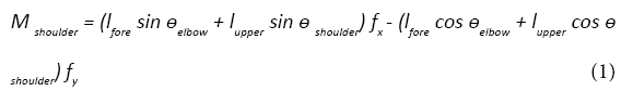
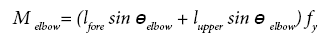
The vector of output force on distal extremity is necessary to be calculated in order to estimate the distribution of each muscle using the musculo-skeletal model described as above. The vector of the output force on the distal extremity can be calculated from net moments at joints. Figure 3 shows the relationship between the output force on the distal extremity and the net moments of shoulder joint and elbow joint. The output force of x axis is represented by fx, that of y axis is represented by fy. The angle of shoulder joint and elbow joint are represented by θshouler and θelbow. The link length of upper arm and forearm are represented by lupper and lfore. The net moments of shoulder joint and elbow joint are represented by Mshouler and Melbow. The relationship between the output force and the net moments is represented as follows. The vector of output force can be calculated by solving the simultaneous formulas.

Figure 3: Relationship between output force on the distal extremity and net moment.
 (2)
(2)
The distribution of each muscle force can be estimated with the obtained output force on the distal extremity (fx, fy) by applying to the model in Figure 3. Then the muscle forces can be estimated with the scale of the vector of the output force on the distal extremity.
Determination of working condition in lifting operation
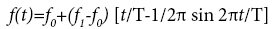
An angle variations of joints during lifting operations were suggested to be approximated by the equation described as follow [15].
 (3)
(3)
Then, T is the duration of angle variation, f0 is the angle at t=0 [s] (initial posture) and f1 is the angle at t=T[s] (final posture). These parameters, T, f0, f1 for simulation of lifting operation are need to be determined in advance. The positions of joints can be calculated from the angle variations obtained by the equation (3) and the link length li of each segment.
In the determination of workable weight, the motion obtained from the way described above is repeated by gradually increasing the weight of the object by 0.1 kg in computer. The workable weight is determined to keep each muscle force of upper limb under target normalized muscle force using the musculo-skeletal model described in section “Estimation of muscle forces with musculo-skeletal model”. The flowchart to determine workable weight is shown in Figure 4. First, the working cycle t1, when the position of hand is higher than target height, is determined. Then, the lifting motion from 0 sec to t1 sec is created from the angle variations obtained by the equation (3). The motion is repeated by gradually increasing the weight of object by 0.1 kg. The maximum working weight, which keeps each muscle force of upper limb under the target normalized muscle force, is determined. Actually, weight magnitude is dependent on joint angle in lifting operation. However, the relationship between weight magnitude and joint angle is complex and cannot be accurately expressed. Therefore, this study assumes that weight magnitude is independent of joint angle.

Figure 4: Flowchart to determine the workable weight.
Identification of parameter for estimation of muscle forces
It is necessary for estimation of muscle forces described in section “Estimation of muscle forces with musculo-skeletal model” to identify the maximum muscle force of each muscle. The maximum muscle force of each muscle can be obtained from maximum output force distribution on the distal extremity. Experiments by actual workers are required to measure the maximum output force distribution. The participants of experiments need to output all directions with maximum forces in order to measure the maximum output force distribution. However, the results of these trials are susceptible to error due to muscle fatigue. Then, this study used the method measuring the maximum output force distribution suggested by Oshima et al. [16]. The method can describe the maximum output force distribution in the shape of hexagon geometrically with measured forces of only four directions. The aluminum frame with a handgrip on a three component dynamometer (KYOWA Corp. LSM-B-SAI) shown in Figure 5 was used to measure maximum output forces of upper limb. The posture of the upper limb of participant can be adjusted with the three component dynamometers and seat changed. Five participants, after informed consent, participated in this study. Table 1 shows the characteristics of the participants. Each participant was indicated to output maximum muscle force to four directions. The maximum points measured by the three component dynamometer were used to describe the maximum output force distribution. Table 2 shows the maximum muscle force of each muscle determined from the experiment. Figure 6 shows the result of the maximum output force distribution of each participant in the experiment.

Figure 5: Measuring equipment of the output force distribution on the distal extremity.

Figure 6: Maximum output force distribution on musculoskeletal model considering the role of antagonistic muscles and biarticular muscles.
| Subject | Height (cm) | Mass (kg) | Age (years) | Sex |
|---|---|---|---|---|
| A | 165 | 47 | 23 | Male |
| B | 179 | 60 | 23 | Male |
| C | 177 | 67 | 21 | Male |
| D | 169 | 57 | 22 | Male |
| E | 172 | 59 | 21 | Male |
Table 1: Characteristics of the participants.
| Muscle | Maximum Forces [N] | ||||
|---|---|---|---|---|---|
| Participant A | Participant B | Participant C | Participant D | Participant E | |
| f1(deltoid anterior (Da)) | 131.8 | 252.6 | 357.2 | 244.8 | 183.2 |
| e1(deltoid posterior (Dp)) | 148.8 | 241.4 | 172.0 | 152.2 | 205.4 |
| f2(brachialis (Br)) | 138.4 | 312.0 | 299.2 | 250.8 | 394.6 |
| e2 (lateral head of triceps brachii (Tla)) | 46.4 | 288.4 | 185.8 | 52.4 | 89.4 |
| f3(long head of biceps (Blo)) | 123.2 | 69.2 | 86.0 | 198.4 | 158.8 |
| e3 (long head of triceps brachii (Tlo)) | 123.2 | 69.2 | 86.0 | 198.4 | 158.8 |
Table 2: Maximum force of each muscle on musculoskeletal model considering the role of antagonistic muscles and biarticular muscles.
Simulation of working condition in lifting operation
The working condition in lifting operation was determined with the method described in section “Determination of working condition in lifting operation” and the parameters determined in section “Identification of parameter for estimation of muscle forces”. In the determination of workable weight, the workable weight was determined under the condition that the target lifting height was 1.0 m.
Participants conducted the lifting operation in advance in order to determine the parameters, T, f0, f1 for the simulation of lifting operation. The conditions of lifting operation were that the lifting weight was 5.0 kg and the lifting height was 1.5 m. The participants’ motions of the lifting operation were recorded at 60 frames per second using the CCD camera (SONY Corp. XC-009). The participants were instructed to keep their feet in the same position during the lifting operation. The experimental system included a slide board to put object on. The shape of the object was cuboid with handgrips. The positional data of joints obtained from captured images were smoothed using a Butterworth filter (cut-off frequency 6 Hz) [17,18].
The determined parameters, T, f0, f1 for the simulation of lifting operation of each participant are shown in Table 3. The link length li of each segment of each participant is shown in Table 4.
(a) Participant A
| Foot | Leg | Thigh | Lower Trunk | Torso | Upper Arm | Forearm | Hand | Head | |
|---|---|---|---|---|---|---|---|---|---|
| f0[Degree] | -180.0 | 47.9 | -154.3 | 60.3 | 60.3 | -92.3 | -29.8 | -34.9 | 34.5 |
| f1 [Degree] | -180.0 | 76.9 | -271.4 | 88.8 | 88.8 | -68.4 | 39.5 | -15.9 | 44.2 |
| T [S] | 5.1 | ||||||||
(a) Participant B
| Foot | Leg | Thigh | Lower Trunk | Torso | Upper Arm | Forearm | Hand | Head | |
|---|---|---|---|---|---|---|---|---|---|
| f0[Degree] | 176.8 | 47.9 | -154.3 | 60.3 | 60.3 | -92.3 | -29.8 | -34.9 | 34.5 |
| f1 [Degree] | 176.8 | 76.9 | -271.4 | 88.8 | 88.8 | -68.4 | 39.5 | -15.9 | 44.2 |
| T [S] | 5.1 | ||||||||
(c) Participant C
| Foot | Leg | Thigh | Lower Trunk | Torso | Upper Arm | Forearm | Hand | Head | |
|---|---|---|---|---|---|---|---|---|---|
| f0 [degree] | 177.9 | 54.6 | -149.6 | 55.3 | 55.3 | -93.8 | -19.6 | -50.8 | 37.8 |
| f1 [degree] | 179.0 | 77.2 | -264.8 | 93.6 | 93.6 | -42.4 | 38.5 | -6.8 | 70.6 |
| T [s] | 3.5 | ||||||||
(d) Participant D
| Foot | Leg | Thigh | Lower Trunk | Torso | Upper Arm | Forearm | Hand | Head | |
|---|---|---|---|---|---|---|---|---|---|
| f0 [degree] | 168.1 | 44.6 | -167.2 | 42.3 | 42.3 | -96.5 | -30.1 | -39.6 | 37.5 |
| f1 [degree] | 177.1 | 77.1 | -268.3 | 100.1 | 100.1 | -24.3 | 49.0 | 4.2 | 62.3 |
| T [s] | 3.8 | ||||||||
(e) Participant E
| Foot | Leg | Thigh | Lower Trunk | Torso | Upper Arm | Forearm | Hand | Head | |
|---|---|---|---|---|---|---|---|---|---|
| f0 [degree] | 179.0 | 50.9 | -156.4 | 60.5 | 60.5 | -90.9 | -29.5 | -49.6 | 57.6 |
| f1 [degree] | 179.0 | 79.2 | -267.9 | 95.8 | 95.8 | -36.3 | 33.4 | -20.1 | 78.0 |
| T [s] | 3.8 | ||||||||
Table 3: Parameters, T, f0, f1 for the lifting operation simulation of each participant.
| Participant | Foot [m] | Leg [m] | Thigh [m] | Lower Trunk [m] | Torso [m] | Upper Arm [m] | Forearm [m] | Hand [m] | Head [m] |
|---|---|---|---|---|---|---|---|---|---|
| A | 0.27 | 0.48 | 0.35 | 0.14 | 0.42 | 0.28 | 0.26 | 0.12 | 0.30 |
| B | 0.25 | 0.48 | 0.38 | 0.15 | 0.46 | 0.23 | 0.27 | 0.12 | 0.28 |
| C | 0.25 | 0.50 | 0.44 | 0.16 | 0.47 | 0.25 | 0.27 | 0.11 | 0.26 |
| D | 0.28 | 0.49 | 0.41 | 0.13 | 0.40 | 0.28 | 0.26 | 0.11 | 0.28 |
| E | 0.25 | 0.49 | 0.37 | 0.15 | 0.45 | 0.26 | 0.27 | 0.10 | 0.28 |
Table 4: Link length of each segment of each participant.
In the determination of the workable weight by the method described in section “Determination of working condition in lifting operation”, the net moment of each joint was calculated on each motion with the human rigid segment model and Newton’s equation. The normalized muscle force (defined as %MVC) of each muscle was calculated by the method described in section “Estimation of muscle forces with musculo-skeletal model”. Then, the weight of each segment is calculated from the mass of the participant with the distribution measured by Ae et al. [19]. The condition of lifting operations was that the mass of the object was constant during lifting operation.
The result of the determined workable weight is shown in Table 5. The results shows that the estimated workable weight is different from individuals because of muscular strength characteristic. In the result of the determined workable weight of the participant B was small. The maximum muscle forces of the participant B were not small as shown in Table 2 and Figure 6. The reason, that the workable weight was small in spite of the strong maximum muscle forces, was considered that the motion of the lifting operation. This means that the participant B conducted motion with more loaded than any other participant. Then, in the participant B, the workable weight was estimated by using the motion of lifting operation simulated by the angle variations of joints of the other participants. The motion is defined as “Angle Variation Modified Pattern”. The angle variations of the joints of the other participants were used by the parameters T, f0, f1, for simulation of lifting operation as shown in Table 3. The result of the workable weight by using the angle variations of joints of the other participants is shown in Table 6. The result in Table 6 indicates that the maximum workable weight is different when the motion of lifting operation is different, even if the muscular strength characteristic is same.
| Participant | A | B | C | D | E |
|---|---|---|---|---|---|
| Mass [kg] | 9.6 | 9.5 | 12.6 | 14.9 | 10.9 |
Table 5: Determined workable weight on the condition that the lifting height is 1.0 m.
| Original (Participant B) | Parameters of Participant A | Parameters of Participant C | Parameters of Participant D | Parameters of Participant E | |
|---|---|---|---|---|---|
| Mass [kg] | 9.5 | 11.0 | 10.4 | 9.4 | 9.0 |
Table 6: Determined workable weight by using parameters for the lifting operation simulation of another participant.
The result of the normalized muscle forces (%MVC) of the participant B under the condition that the lifting weight was 9.5 kg (Original Pattern) is shown in Figure 7. In Figure 7, the muscle f3 (Blo) were more activated than any other muscle in the lifting operation. Then, in this discussion, the muscle f3 (Blo), which works mainly in the lifting operation, is focused on. Figure 8 shows the result of the variation of the normalized muscle force (%MVC) of muscle f3 (Blo) both under the condition that the participant B operated with the lifting weight 9.5 kg (Original Pattern) and under the condition that the motion of the Participant B was simulated by the angle variations of joints of the Participant A with the lifting weight 9.5 kg (Angle Variation Modified Pattern). In Figure 8 (Original Pattern), the normalized muscle force (%MVC) of muscle f3 (Blo) increased between the beginning and the end of the lifting operation. On the one hand, in Figure 8 (Angle Variation Modified Pattern), the normalized muscle force (%MVC) of muscle f3 (Blo) was constant between the beginning and the end of the lifting operation.

Figure 7: Estimated normalized muscle force (%MVC) of each muscle of participant B on the condition that the lifting weight is 9.5 kg and the lifting height is 1.0 m.

Figure 8: Estimated normalized muscle force (%MVC) of muscle f3 comparing between original pattern and angle variation modified pattern on participant B.
Then, Figure 9 shows the posture and the maximum output force distribution on the distal extremity estimated by the method described in section “Estimation of muscle forces with musculo-skeletal model” comparing between at the beginning and at the end of the lifting operation on each motion pattern. In Figure 9 (Original Pattern), the maximum output force distribution to the vertical direction was different between at the beginning and at the end of the lifting operation. In Figure 9 (Angle Variation Modified Pattern), the maximum output force distribution to the vertical direction was not different between at the beginning and at the end of the lifting operation. This is considered the reason that the determined workable weight was different between Original Pattern and Angle Variation Modified Pattern.

Figure 9: Posture and maximum output force distribution on the distal extremity comparting between the beginning and the end of the operation (a = Original Pattern, b = Angle Variation Modified Pattern).
Figure 10 shows the posture and the maximum output force distribution on the distal extremity at the end of the lifting operation, when the normalized muscle force (%MVC) of muscle f3 (Blo) is maximum on Original Pattern, comparing between Original Pattern and Angle Variation Modified Pattern. In Figure 10, the maximum output force distribution to the vertical direction of Angle Variation Modified Pattern was larger than that of Original Pattern. This means that the working load is different depending on the working posture, even if the maximum muscle forces of the upper limb are same. The result of Figure 10 indicated that the output force to the vertical direction was larger as the angle of elbow joint was smaller.

Figure 10: Posture and output force distribution at the end of the lifting operation comparting between the original pattern and the modified angle variation pattern.
In this study, the optimal workable weight could be determined depending on the motion of each participant by not exceeding 70% of the maximum muscle force by using the musculo-skeletal model considering the role of antagonistic muscles and biarticular muscles. Furthermore, the results of this study indicated that the maximum workable weight was larger as the posture changed, even if the maximum muscle forces of upper limb are same. In lifting operation, the maximum workable weight was larger as the angle of elbow joint was smaller during the operation. The results of this study showed that the musculo-skeletal model considering the role of antagonistic muscles and biarticular muscles was effective for the determination of working condition and the evaluation of lifting operation.
This study suggested the method to determine the optimized working condition for each worker considering the physical property of worker, especially muscular strength characteristic. The physical property of worker, especially muscular strength differs according to the worker. The working condition contained the workable weight in the lifting operation. The results of this study can be used to simulate the working condition considering the physical properties with the role of antagonistic muscles and biarticular muscle.
There are some limitations of this study as follows. This study only investigated single lifting operation without considering frequency and duty cycle. This study also did not consider the effect of muscle fatigue. Furthermore, this study assumed that the weight magnitude is independent of joint angle. This study also assumed that the target height is independent of joint angle. It is necessary to solve these limitations in order to apply the proposed method to real environment.
Nonetheless, the novelty of this study is to propose the method to determine the optimized working condition in lifting operation considering the physical properties with the role of antagonistic muscles and biarticular muscle. The results of this study may help the plant manager to design the working condition and determine personnel distribution according to physical characteristic of worker. This study will continue to evaluate not only single lifting operation but also other motions. Furthermore, this study will continue to estimate not only muscle forces but also muscle fatigue. Then our future study will make it possible to optimize the working environment and result in a productivity improvement of industry.