Journal of Chemical Engineering & Process Technology
Open Access
ISSN: 2157-7048
ISSN: 2157-7048
Short Communication - (2021)Volume 12, Issue 7
In this paper a novel ratio control scheme is proposed for fluid catalytic cracking unit. Based on a developed mathematical model, the dynamic simulator of a fluid catalytic unit is used to implement two schemes of ratio controller. The performance of the control scheme proposed here is tested using integral Absolut error. The results of simulation are successfully compared with the plant data. Comparison with PI controller, the ratio controller scheme one in maintaining controlled variables is very close to their set points. Here, with an application to a FCC unit of ratio control scheme one results obtained is found to be acceptable and it would be effectively used for improved process control of FCC in refinery process industry.
Fluid catalytic cracking unit; Dynamic simulator; Ratio controller; PID controller
The fluid catalytic cracking (FCC) unit is one of the most important and complex processes in the petroleum refining industry. It converts heavy petroleum fractions into a range of hydrocarbon products like gasoline, liquefied petroleum gas (LPG), and olefins by using a zeolite catalyst. The control of the FCC unit was difficult and it was considered as a challenge control problem, it was also of great economic significance in a modern petroleum refinery. There are some aspects of the basic difficulties in the study of process control for FCC unit as to multivariable, nonlinear [1].
There are many attempts to develop a dynamic model and simulate entire FCC unit [1-7]. Also, the structure of the different applied controller such as PID, fuzzy, model predictive control, artificial neural networks and optimal control are designed to solve challenging tasks of FCC unit by many attempts [8-12]. All the applied control methods try to solve the problem under several considerations such as stability, reject of disturbance high performance for wide range of conditions and with minimum cost. The most problems of these attempts are the complex dynamic model, validity of simulator program, reaction kinetics and different operating conditions. Ahmed [13] developed the decoupler controller from a model of FCC unit to cancel the interaction between loops. He proved that the decoupling is effective, stable and it was able to offer good dynamic performance for most disturbances, especially where there is change in the feed flow rate to the riser. Karthika et al. [14] compared the performance of FCC unit with the decentralized PID control scheme with the optimal control scheme using Matlab/Simulink. The results of simulation disclose the effectiveness of the optimal control scheme over the decentralized PID control scheme.
Little papers have been done to develop the structure of the ratio controller scheme of FCC unit. Hagglund [15] proposed a new ratio control structure called blend station to enhance the ratio control performance during the unsteady state caused by the set point change. Visioli [16] developed two kinds of ratio control methods based on blend station structure and standard PI controller for automatic tuning procedure in simulation and experimental study. He found the ratio control is effectiveness of the methodology for a wide range of processes and easy tuning and understanding by operators. Oua et al. [17] proposed a novel ratio control scheme for stable and unstable processes with time delay. They concluded through the simulation study that the setpoint and load disturbance responses of the ratio control system can be independently and conveniently tuned by a single control parameter. In addition, the proposed ratio control scheme can provide quantitative performance estimation. Kumar and Kaistha [18] evaluated the three different ratio control schemes in a two-temperature control structure for a methyl acetate reactive distillation column. They concluded that maintaining the two fresh feeds in ratio does not lead to an improvement in the control performance and robustness. Nguyen et al [19] applied predictive feed-forward and PID control scheme based on model predictive control (MPC) that copes with ratio control for interacting delayed processes. They found that the new ratio control scheme, a better performance in output ratio control is achieved with smaller control effort. Tay et al. [20] developed a new ratio control strategy for controlling temperature uniformity of a silicon wafer substrate. They found the series ratio control has good performance in the transient response. Srinivas et al. [21] used ratio control for maintaining the optimal air-fuel ratio in the furnace. They concluded that the maintaining optimum air-fuel ratio in efficient working of furnace. The objective of this study is to design the new ratio controller of FCC unit depend on position of controller and tested by dynamic simulation with comparison with PI controller to show the closed-loop performance of the FCC unit.
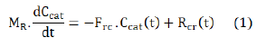
The main parts of FCC unit are riser and regenerator. Both mass and heat balance of riser and regenerator are complex. The cracking reaction is carried out in the riser where desired reactions include cracking of the high boiling gas oil fractions into the lighter hydrocarbons. The regenerator of the FCC unit is assumed to be a constantly stirred tank reactor where combustion reaction takes place. The undesired reactions include carbon formation reactions and a regenerator where the carbon removal reactions take place. The effect of the steam on the energy balance is neglected. Most of the coke on the catalyst pellets would be already combusted in the regenerator. The coke generated by the cracking reaction is usually known as catalytic coke. The mass balance of catalytic coke in the riser can be written as:
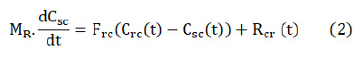
The total coke on the spent catalyst in the reactor is the sum of the catalytic coke and the residual coke on the regenerated catalyst:
The dynamics of the cracking reaction in the riser is negligible when compared to the dominant time constants of the system. The heat balance is handled in accordance with a lumped parameter system. This leads to the following energy balance equation in the

The reactions taking place in the regenerator are coke combustion reactions. This coke is the byproduct of the cracking reaction taking place in the riser and gets deposited on the catalyst surface in the course of cracking.
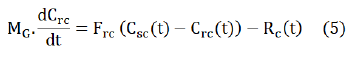
The equations of the model for the regenerator mass balance are:
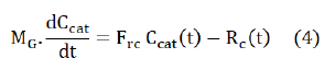
Then the mass balance of total carbon on the regenerated catalyst in the regenerator becomes:
The energy balance in the regenerator is given by following equation:

Ratio control method
The ratio control is a special type of feed-forward control that has had widespread application in the process industries. The purpose of ratio control is to keep the value of one variable as a ratio proportional to another variable. The two variables are usually flow rates. The two variables are measured, but only one of them is controlled and it is usually used in system with coupling. Ratio control is applied almost exclusively to flows and the system load is called the wild flow, so it cannot be used as a manipulated variable and another variable is controlled variable, so can be used as a manipulated variable.
Riser temperature controller measures the riser temperature, compares that measurement with the set point, and if there is a difference between the two values, changes its output signal to the regenerated catalyst in order to eliminate the error. The holdup and temperature of regenerator are changed after period of the time. This means that regenerator temperature can only initiate its corrective action after an error has already developed. This mechanism required large of the time and specification of process is changed through this time. Thus you can conclude that feedback control loops can never achieve perfect control of a process, that is, keep the output of the process continuously at the desired set point, value in the presence of load or set point changes. There exists a situation where ordinary action is insufficient to produce the desired response of a given process. In this case, a control configuration such as ratio control is used. Air flow must be maintained in correct proportion to the regenerated catalyst flow for correct regenerator operation and final product. Ratio control automatically provides the correct proportion of air flow rate to regenerator. The two variables are usually flow rates of regenerated catalyst and air the ratio of the two variables is:
The ratio controller consists of flow transmitter which senses the flow rate of the regenerated catalyst and second flow control of inlet air to regenerator for holding the catalyst-air ratio at optimum value. The air flow rate is regulated by ratio controller with respect to the flow rate of the regenerated catalyst to provide the specified control ratio. The ratio controller reacts to the resulting input signal of catalyst flow rate by adjustment of the control valve in the air input line. There are two schemes of ratio control considered in the paper. First, the ratio controller loop locates inner the regenerated temperature control loop. The first scheme for ratio control is shown in Figure 1. Secondly, the ratio controller loop locates outer the regenerated temperature control loop. The second scheme for ratio control is shown in Figure 2.

Figure 1: Block diagram of first scheme of ratio controller.

Figure 2: Block diagram of second scheme of ratio controller.
Simulation works
The FCC unit consists of riser, regenerator, and main fractionator these three main parts are of particular interests both in industrial and research circles.. The riser reactor is a vertical standpipe at about (33) m in length and (0.8 m) in diameter. Preheated gas oil at about 494 ℃ is sprayed into riser bottom, where it mixes with hot regenerated catalyst at about 695 ℃ to produce a reaction temperature of about 546℃. It is assumed that the vaporization of the gas oil is instantaneous. Vaporized feed pneumatically conveys the catalyst from bottom to the top of the riser. In the riser endothermic cracking takes place at a temperature and pressure of about 546℃ and 2.9 bar respectively. The catalyst and product gases from the riser enter the disengaging vessel. The separation of the catalyst from the product streams occurred in this vessel by using deflectors and cyclones. Following this the spent catalyst is transported to the regenerator where coke laid down on the catalyst surface, is burned off using air. The combustion of the carbon and hydrogen coke components is take place in regenerator with (11 m) height and (5.8 m) in diameter, a highly exothermic reaction takes place at a temperature and pressure of about 695 ℃ and 2.9 bar respectively then the regenerated catalyst is recirculated to the reactor and supplies the heat required for cracking reaction. A simulation program is built for the FCC unit by using the program Matlab/ Simulink version (R2011a) from (Math works). It is software for a simulation of dynamic model analysis. It consists of a Simulink part to build the models and study of the control system. The simulation program is built for FCC unit in the form of a set of systems and each system component with a set of subsystems which depend on the mathematical model equations for FCC unit [22].
The validity of the simulation work
The present simulation work was validated by comparing the steady state prediction with the results of simulation of some authors Malay et al., [23]; Ali et al., [24]; Ali and Rohani, [2] and the industrial plant data. The industrial plant data from Universal Oil Product (UOP) type FCC unit finding in Malay et al., [23] were used to verify the present simulation work. Table 1 shows this comparison [24]. The present simulation results are presented for the riser temperature, TR, regenerator temperature, TG, gasoline yield, Y1, light gas yield, Y2, and coke formed, Y3. The results show the best prediction of the gasoline yield, riser and regenerator temperatures but the highest deviation in light gases yield and amount of coke. The deviation percent of the riser and regenerator temperatures from the plant data are 0.855 and 0.864 respectively; these results are in closer agreement with the plant data. However, there are 6.56, -14.18 and -21.72 in gasoline, light gases and coke yield respectively. The largest deviation, among the five variables, in the amount of coke was obtained. Compared to the simulation of other works, the present simulation results of the gasoline yield, riser and regenerator temperatures are better. However, the percent deviation of the coke amount and light gases yield from the plant data obtained are relatively high but give the lowest deviation from plant data among the other studies.
| Parameter | Plant | Ref.1 | Ref.2 | Ref.3 | Present simulation | %Dev.P | %Dev.1 | %Dev.2 | %Dev.3 |
 , (K) , (K) |
795 | 843 | 749 | 843 | 801.8 | 0.855 | -4.88 | 7.04 | -4.88 |
 , (K) , (K) |
960 | 1143 | 939 | 1143 | 968.3 | 0.864 | -15.28 | 3.12 | -15.28 |
 , (wt%) , (wt%) |
43.9 | 51.3 | 42.7 | 51.3 | 46.78 | 6.56 | -8.81 | 9.55 | -8.81 |
 , (wt%) , (wt%) |
13.82 | �.. | �.. | �.. | 11.86 | -14.18 | �. | �� | �� |
 , (wt%) , (wt%) |
5.8 | 5.8 | 6.1 | 5.79 | 4.54 | -21.72 | -21.72 | -25.57 | -21.58 |
Table 1: Comparison of present simulation results with plant data.
The deviation between the present simulation results and the plant data are attributed to various factors. The simplifying assumptions were imposed on the model such as the adiabatic process, the steam for atomizing and separation were negligible and used values for physical chemical properties (the heats of reactions of the cracking and the combustion reactions) are identified as source of errors. Also, the used kinetic parameters from the literatures depend on the catalyst type, the catalyst activity, the age of the catalyst in operation, and the quality of the feed stock are other source of error. Moreover, the lumping and products represent another source of error. Despite all these, the deviations of the present simulation results from industrial plant data are relatively small.
Control of FCC unit
The riser temperature has to be maintained at a certain level to provide a desired maximum conversion of the feed oil. The main manipulated variables are the spent and regenerated catalyst flow rates that may be changed by regenerated and spent slide valve position. The regenerator temperature has to be maintained at a certain value to allow a stable removal of coke from the catalyst. Overriding a high temperature limit produces a permanent catalyst deactivation; a reduction under a lower limit leads to coke accumulation on the regenerated catalyst. The selected disturbances reflect main upsets possible to affect the normal operation of the unit. A positive step change has been selected for these disturbances. The disturbance entering the process are 10% in the gas oil feed flow rate, temperature of gas oil and air temperature. The set point values used in simulation were TR=795 K and TG=960 K. Many simulation runs were carried out for PI and ratio for two schemes controllers for a two steps change in gas oil flow rate, gas oil feed temperature and air temperature are shown in Table 2. Figures 3 to 5 show the comparison between the responses of riser temperature at different control methods and Figures 6 to 8 shows the comparison between the responses of regenerator temperature at different control methods. It can be seen from Figure 3 that the better control performance is obtained with ratio controller scheme one which is corroborated with the IAE values shown in Table 2. Simulation results in Figure 3 shows that the effect of disturbance in gas oil temperature on the control performance to produce a high overshoot of PI controller. Moreover, the ratio controller scheme one shows good disturbance rejection. Ratio controller scheme one succeeds to counteract the disturbance effects, presenting small overshoot and short settling time. For the ratio controller scheme two, we have found similar control performance to that displayed by the PI controller case. This seems to indicate that, for regulation control purpose, the ratio controller scheme two does not add significant performance into the control loop. On other hand, worst performance was observed for the PI controller. Compared to ratio controller, The PI control scheme has inferior control performance showing higher overshoot and longer response time. The PI control scheme presented unsatisfactory control performance for all controlled variables in the case of air flowrate disturbance. For the case of the other investigated disturbances the control performances of ratio scheme two and PI control schemes are not essentially affected. Table 2 shows the ISE computed values for temperature controllers at different control methods. Through the present simulation results, the setting time for ratio scheme one to arrive the set desired set point was about 5 minute, while setting time for ratio scheme two and PI are about 30 min. and 45 min. respectively, therefore, ratio scheme one is preferable It can be seen that IAE value of ratio controller scheme one is less than scheme two. It is clear that, at though the performance of the ratio scheme two is comparable in the disturbance rejections. The ratio control schemes two are characterized by the existence of higher overshoot and a longer response time, possibly coupled with small offset, but the control performances are not considerably affected. The ratio scheme two did not reveal improvements compared to ratio case 1 scheme.
| Item no. | Disturbance variable of | Value | PI | Ratio scheme (1) | Ratio scheme (2) | Unit |
|---|---|---|---|---|---|---|
| 1 | Gas oil flow rate, kg/sec | 20 - 22 | 87.1841 | 9.0250 | 89.7969 | Riser |
| 2 | Gas oil feed temperature, K | 494 - 543.3 | 164.8995 | 16.0952 | 161.8236 | |
| 3 | Air temperature, K | 378 â?? 415.8 | 23.3556 | 0.9944 | 11.3889 | |
| 4 | Gas oil flow rate, kg/sec | 20 - 22 | 69.8465 | 1.3788 | 62.7779 | Regenerator |
| 5 | Gas oil feed temperature, K | 494 - 543.3 | 206.9341 | 14.9406 | 145.0579 | |
| 6 | Air temperature, K | 378 â?? 415.8 | 100.496 | 16.1144 | 113.1095 |
Table 2: The integral absolute error (IAE) for control methods.

Figure 3: Responses of riser temperature at different control methods to step change in gas oil feed temperature from 494 to 543.4 K at set point 795 K.

Figure 4: Responses of riser temperature at different control methods to step change in gas oil feed flowrate from 20 to 22 kg/sec at set point 795 K.

Figure 5: Responses of riser temperature at different control methods to step change in air temperature from 378 to 415.8 K at set point 795 K.

Figure 6: Responses of regenerator temperature at different control methods to step change in gas oil feed temperature from 494 to 543.4 K at set point 960 K.

Figure 7: Responses of regenerator temperature at different control methods to step change in gas oil feed flowrate from 20 to 22 kg/sec at set point 960 K.

Figure 8: Responses of regenerator temperature at different control methods to step change in air temperature from 378 to 415.8 K at set point 960 K.
The paper presents a new control method and dynamic simulator for the FCC unit. The simulation results showed that the steady state predictions are agreement with the results of simulation of some authors and the industrial plant data. Compared with the PI control, ratio controller case one presents better control performance. The ratio controller case one response is more quickly than ratio controller case two. The ratio control case two in turn brought the riser and regenerator temperatures to the set point by rigorous adjustment of the flow rate and temperatures in a long response time. This indicates that the ratio controller case one give smoother and better control performance than the case two with smaller IAE error values, when disturbances are introduced into the systems. The ratio controller case one give less error and give better control results, but finally, the simulation results shows that the ratio controller case one provide better performance because the case one has lower time to reach the steady state value and the response much more stable.
This work is supported by Tikrit University, Research Grant No. (433/7/7) in 08/03/2015.
Received: 07-Jul-2021 Accepted: 21-Jul-2021 Published: 28-Jul-2021 , DOI: 10.35248/2157-7048.21.12.420
Copyright: This is an open access article distributed under the terms of the Creative Commons Attribution License, which permits unrestricted use, distribution, and reproduction in any medium, provided the original work is properly cited.