International Journal of Advancements in Technology
Open Access
ISSN: 0976-4860
ISSN: 0976-4860
Review Article - (2023)Volume 14, Issue 3
In this work, we studies the principle of ground electrode current field through ground communication technology, signal design, and optimal working mode of excitation source, so as to adapt the working mode, working frequency, and transmission medium condition of signal transmission. Through waveform design, energy is concentrated in the main conduction direction, which is beneficial for signal filtering at the receiving end and achieving high reliability data transmission; on this basis, onsite environmental testing was conducted to verify the detection and recognition technology of weak signals. Signal design and detection recognition are a very important part of the grounding electrode current field through ground communication technology. The grounding electrode current field through ground communication technology is mainly applied to solve the problem of communication between rescue personnel and trapped personnel before and during tunnel engineering collapse and rescue.
Current field; Ground-penetrating communication; Signal design; Detection; Identification
China has become the world’s largest country in terms of tunnel and underground engineering construction scale and speed. During the tunnel excavation process, especially before the completion of the inverted arch and secondary lining, collapse accidents often occur; after the accident, the thickness of the collapsed rock and soil between the tunnel entrance and the con-struction face is generally 30-200 meters. This type of closed door collapse will form an under-ground enclosed space between the tunnel construction face and the collapsed body. The conventional installed underground communication system is basically paralyzed, making it difficult for trapped personnel to contact ground search and rescue personnel, resulting in low search and rescue efficiency. High reliability communication technology equipment is one of the key technologies in the emergency rescue process.
Ground-penetrating communication technology is a wireless communication technology that uses the Earth’s strata as a communication channel. Therefore, this technology is not affected by disasters such as underground engineering collapses and can achieve two-way communication, representing an important communication method for emergency rescue in the case of underground engineering disasters such as those in tunnels and mines. However, in such situations, the achievement of bidirectional signal transmission is a key bottleneck problem that this technology faces [1,2].
At present, there are three main types of ground-penetrating communication technologies studied domestically and internationally: Magnetic induction near-field electromagnetic wave ground-penetrating communication, ground electrode current field ground-penetrating communication, and mechanical vibration wave ground-penetrating communication. Near-field electromagnetic wave and elastic wave transmission through the ground based on magnetic induction antennae have been widely discussed by researchers at home and abroad; however, owing to the need for larger circular antennae and greater power, the transmission attenuation is considerable, making the technology susceptible to the influence of geological media, resulting in poor applicability. Ground electrode current field communication has the advantages of small antenna size, a simple structure, and flexibility, enabling the achievement of stable communication and long-distance transmission [3,4].
In 2012, Spanish scholar V. Bataller proposed a current field through ground communication based on the injection of ground electrode current and the detection of potential differences between receiving electrodes, and proposed a circuitequivalent model for electrode impedance. In 2015, L. van and C. Sunderman comprehensively considered the noise level and signal attenuation characteristics in soil, and derived an analytical solution for the field distribution of an electrode-based Through The Earth (TTE) communication system in a uniform half space. In 2016, researchers from Beijing Jiaotong University studied the propagation and attenuation characteristics of electromagnetic waves in layered media channels and established a layered media model and calculation model. In 2017, a research team from Beijing University of Information Technology designed an antimultipath interference information system based on a direct sequence spread spectrum. By using highly random logistic spread spectrum codes, the anti-multipath interference performance of the tunnel engineering geological exploration in-formation system was effectively improved. In 2017, researchers from China University of Mining and Technology designed a wireless underground magnetic induction information transmission system to achieve short-distance wireless data transmission in underground environments. In 2017, Ralchenko et al from Carlton University in Canada discovered the presence of lowfrequency signals on two slender conductors near a transmitter, which were found to considerably increase the signal transmission distance [5-11].
In 2021, Dongkuo University in Seoul, South Korea developed a practical multi hop magnetic induction wireless underground sensor network deployment model and evaluated the transmission and reception performance of the network. These studies provide us with important references and references, and have important research significance for promoting the development and application of ground penetrating communication technology. In 2021, Liu Baoheng and others from Naval Engineering University constructed a three-dimensional model of an underground electric field, providing complete explicit solutions for three electric field components. Based on the model and expressions, the effects of the offset, relative orientation, length, and operating frequency of the transmitting and receiving antennas on the electric field distribution were simulated and analyzed. In 2023, Zhao Jun and others from Shanxi Mechanical and Electrical Vocational and Technical College used the finite element method to solve the normal potential and abnormal potential of the space field. Based on comsol software, a homogeneous threedimensional geoelectric detection model was constructed, and tetrahedral mesh adaptive algorithm was used for dissection. The numerical solution accuracy was compared and analyzed. Study the distribution and variation of the focusing current field, and determine the range of the focusing effect current ratio coefficient [12-14]. The principle of ground penetrating communication based on the current field of grounding electrodes is to apply low-frequency electrical signals to two electrodes hit on a rock or soil layer, forming a current field in the rock or soil layer. The signal voltage is detected between the two receiving electrodes at a distance, thereby achieving long-distance transmission of signals. This article studies the principle of this technology and the signal design, signal detection and recognition of ground electrode arrays, providing theoretical guidance and experimental basis for further development in this field.
Technical principles
Earth electrode current injection refers to the injection of a certain frequency of current into the ground through one or more earth electrodes below the surface, resulting in a charged volume and the formation of a current field within that volume. The current field can cause the movement of underground charges, resulting in the propagation of electromagnetic waves underground.
The basic steps of the mechanism of earth electrode current injection
The process of injecting a ground electrode current can be divided into the following basic steps:
• Inject current into the ground through a flexibly grounded electrode
• Current moves in the direction of the current through underground charges
• Electric current forms a charged volume underground
• A current field is formed inside the volume, causing the movement of underground charges
• The movement of charges forms electromagnetic waves, thereby achieving ground-penetrating communication.
Factors influencing the mechanism of earth electrode current injection
The implementation of the earth electrode current injection mechanism is influenced by multiple factors, among which the most important factors include the following:
• Electrode shape and material: During the process of current injection into the ground electrode, the shape of the electrode and the quality of the material determine the effect of current injection into the ground and the intensity of the generated current field.
• Frequency and intensity of current: The frequency and intensity of the current have significant impacts on the movement of charges injected into the ground. The frequency and intensity of the current should not be too high, as excessive current can cause serious electromagnetic interference.
• Geological conditions and terrain: Geological conditions and terrain have a significant impact on the propagation rate and amplitude of electromagnetic waves. Some special underground rock formations or terrain conditions can produce phenomena such as re-flection and refraction, which affect the propagation rate and amplitude of electromagnetic waves.
Application of the earth electrode current injection mechanism
Ground electrode current injection is widely used in the fields of earth-penetrating communication, geophysics, underground mineral exploration, etc. Ground electrode current injection is one of the key technical links to achieve ground-penetrating communication, playing an important role in the propagation and reception of underground electromagnetic waves.
The principle of ground electrode current field through ground communication technology
The ground electrode current field penetrate ground communication technology is a communication method that utilizes the ground current field to penetrate the earth medium to transmit information. The principle of this method is that the transmitting device injects a high-frequency current into a pair of electrodes (i.e., ground electrodes) and forms a ground current field signal through the underground ground layer medium. The receiving device detects, identifies, processes, and demodulates the signal by receiving the ground current field signal, thereby achieving information transmission.
The transmitting device injects a high-frequency current into the ground through a ground electrode, and the current field strength decreases with depth. At the same time, reflection, re-fraction, and other phenomena occur at different depths, resulting in different intensities and phases of the injected current. These currents propagate underground, forming a current field.
During the transmission process, the conductivity of underground rock layers can have an impact on the transmission effect, and the shape, size, depth, and contact with the ground of the ground electrode can also lead to changes in the current field.
The frequency used to inject the ground electrode current also affects the transmission effect. Generally speaking, the delay of high-frequency signals underground is shorter than that of lowfrequency signals. Therefore, selecting an appropriate frequency can improve the transmission efficiency of the ground current field through ground communication technology.
Signal design
Due to the special nature of the geological environment, the terrestrial channel is very complex, and the attenuation of highfrequency electromagnetic waves is very severe. In through-theground communication, only lower-frequency waves can be selected for transmission, thereby limiting the bandwidth of the channel. Therefore, the optimal working mode of the excitation source is studied to adapt the signal transmission mode, working frequency, and the condition of the collapsed medium. Through waveform design, energy is concentrated in the main conduction direction, which is conducive to signal filtering at the receiving end and achieving high-reliability data transmission [15]. Signal design includes constant-envelope continuous phase synchronization signal design and OFDM transmission signal design. The details are as follows:
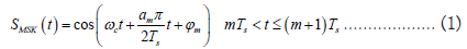
Design of a constant-envelope continuous phase synchronous signal: Constant-envelope continuous signals have good correlation performance, which is conducive to achieving signal synchronization detection. A Minimum-Shift Keying (MSK) signal is used as the synchronization head; the expression of this signal is shown in Equation (1):
Where
 is the carrier angular frequency;
 is the input code unit;
Ts is the code width; and
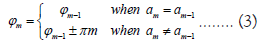
 is the initial phase of the math code unit, which is invariant across a code unit width. According to the continuity of the phase, that is the total phase of the previous code unit, the terminals is equal to the initial total phase of the next code unit (φm) which must satisfy equation (2).

Therefore, Equation (3) is obtained.
MSK is a special type of binary-frequency shift keying with the following characteristics [16].
A constant-envelope that can be amplified using nonlinear amplitude saturation devices;
At the time of symbol conversion, the phase of the signal is continuous, which means that the waveform of the signal does not undergo sudden changes;
The instantaneous frequency is always one of two values, as shown in Equation (4).
The modulation index is 
The synchronous head design adopts an orthogonal modulation method. First, the data to be transmitted are differentially encoded, then serially converted into I-channel and Q-channel signals. Then, each channel is multiplied by the weighting functions ,carriers
  and
and  . Finally, the two channels are summed to obtain a complete MSK signal. The signal modulation box is shown in Figure 1 [17].

Figure 1: MSK signal modulation process.
The waveform of two signals with different frequencies in the MSK signal, that is, when an is +1, the frequency is f1 ; when an is −1, the frequency is f2 . The final designed waveform is shown in Figure 2, with 1 f at 10 Hz, 2 f at 5 Hz, the carrier at 7.5 Hz, the bit cycle at 0.1 s, and the sampling rate at 500 Hz, generating a constant-envelope signal curve with 1600 points [18] (Figure 2).

Figure 2: Constant-envelope synchronous head signal.
The constant-envelope waveform generated by the MSK modulation method has constant amplitude and a continuous phase, and the maximum and average values of the waveform envelope are equal everywhere. Therefore, the peak-to-average ratio of this waveform is 0, which has strong stability and antiinterference ability [19].
OFDM transmission signal design: Orthogonal Frequency Division Multiplexing (OFDM) technology is applied to groundpenetrating communication. Essentially, it converts signals from high-speed serial signals to low-speed parallel signals through serial-to-parallel conversion, with each parallel signal corresponding to a subcarrier with a different frequency. However, the attenuation amplitude of signals at different frequencies varies in terrestrial channels, so OFDM not only exhibits multicarrier but also multichannel performance in ground-penetrating communication. After the serial parallel conversion, the symbol period in each sub channel is increased relative to the original symbol, which reduces the impact of time dispersion caused by the multipath delay expansion of the terrestrial wireless channel on the entire ground-penetrating system. During current field OFDM modulation, appropriate protection intervals are inserted between OFDM symbols, and the protection interval is greater than the maximum delay extension of the terrestrial wireless channel, thereby minimizing inter symbol interference caused by multipath interference in the terrestrial channel. In waveform design, the system uses a cyclic prefix as the protection interval for the ground-penetrating communication system [20,21] (Figure 3).

Figure 3: Orthogonal Frequency Division Multiplexing (OFDM) signal workflow.
The principle of OFDM is to convert signal symbols from high-speed serial signals to low-speed parallel signals through serial–parallel conversion. Each parallel signal corresponds to subcarriers with different frequencies. The earth channel has different attenuation amplitudes for signals of different frequencies, so OFDM is both multicarrier and multi-channel in TTE communication.
In signal design, Cyclic Prefix (CP) is used as the protection interval for the TTE system. In addition, OFDM embeds the transmission information into the carrier coefficients. Its carrier has orthogonality, and the spectrum before the carrier can overlap, which improves spectrum utilization.
The first step in generating OFDM signals is to perform serialto- parallel conversion. Before OFDM modulation, the groundpenetrating communication information is a serial data stream, and the source information is continuously transmitted as in ordinary communication systems. The spectrum of each source data symbol occupies the entire channel bandwidth. After converting the serial data stream into a parallel signal, multiple data symbols can be transmitted simultaneously, and different modulation methods can be used on each subcarrier. In order to improve anti-interference performance, the system uniformly selects QPSK as the modulation method for the subcarriers. Figure 4 shows a constellation diagram of the binary bitstream at the transmitter after QPSK modulation [22].

Figure 4: QPSK-modulated constellation diagram.
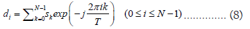
Assuming that the data symbol of each subcarrier is 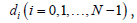 , N is the number of subcarriers, and i is the subcarrier sequence number, the OFDM symbol can be expressed as Equation (5):
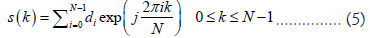
Equation (5) and the Inverse Discrete Fourier Transform (IDFT) (Equation (6)) are consistent.

In the OFDM expression, di can be regarded as the frequencydomain information (X(i)) in the IDFT formula. Therefore, the generation of signals transmitted through the ground in OFDM is equivalent to performing IDFT operations on di, and Inverse Fast Fourier Transform(IFFT) is a fast algorithm for IDFT. Therefore, IFFT is used to generate OFDM signals.
At present, the sampling rate (fs) of the current field transmitter in the system is 1000 Hz, while the number of IFFT points is generally 2N, and N is the number of subcarriers. According to the relationship between the minimum subcarrier interval and the sampling rate, as well as N:
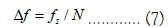
To generate low-frequency ground-penetrating OFDM signals, it is necessary to reduce the subcarrier frequency interval and select 1024 points as the IFFT calculation length: Δf≈0.9766 Hz.
Placing QPSK data on subcarriers 1–10 in the frequency domain ensures that the maximum frequency of the generated OFDM symbol is 9.766 Hz, not exceeding 10 Hz, achieving low-frequency OFDM signal design. The conjugate data of modulation information (di) are placed in a symmetrical position in the frequency domain to ensure that the generated signal after IFFT is a real-number signal. Figure 5 shows the frequency-domain information of low-frequency ground-penetrating OFDM.

Figure 5: Frequency domain information of low-frequency ground-penetrating OFDM signals.
After performing the IFFT operation on frequency domain data, low-frequency OFDM symbols are generated. Figure 6 shows a time-domain waveform carrying a 20 bit ground-penetrating lowfrequency OFDM symbol.

Figure 6: Frequency domain information of low-frequency ground-penetrating OFDM signals.
Due to the multipath effect in the terrestrial channel, signals generate Inter Symbol Inter-ference (ISI) and Inter Channel Interference (ICI) during transmission in the terrestrial channel. Therefore, the period of OFDM symbols is extended to achieve the goal of eliminating ISI and ICI.
Therefore, the tail of the quarter length of the low-frequency OFDM symbol through the ground is selected as the cyclic prefix, as shown in Figure 7, which is the OFDM time-domain symbol with the added cyclic prefix.

Figure 7: A low-frequency ground-penetrating OFDM symbol with a cyclic prefix.
Signal detection and recognition
Due to the special nature of information transmission in closed collapsed-earth electrodes, the received voltage in the information transmission system based on the current field of the earth electrode rapidly decays with increased penetration distance. When the penetration distance exceeds 100 m, the voltage value detected by the receiving end is extremely low. The purpose of weak signal detection at μV or even nV levels is to extract signals submerged in noise.
In order to verify the correctness of the signal design proposed in this article, we conducted on-site testing on a tunnel under construction in Shunyi District, Beijing, using the unfinished part in the middle. The tunnel is 8 m wide and 6 m high, and the unconnected part is 63 m long. The tunnel is 20 m under the ground, and the ground electrodes are 3 m apart. The ground electrode is 1.5 m deep into the ground.
A schematic diagram of the testing structure is shown in Figure 8, and the testing site is shown in Figure 9.
We verified the transmission feasibility and reliability of the signal design in actual tunnel application sites through testing experiments in tunnels under construction.

Figure 8: Schematic diagram of the testing structure.

Figure 9: Testing site.
In the information transmission system of the earth electrode current field, due to the complexity of the electrical conductor of the collapsed medium, power-frequency interference and the earth current field form noise during signal reception, interfering with signal detection. Therefore, external electromagnetic environment testing was conducted to analyze interference characteristics and verify anti-interference technology. Figure 10 shows the timedomain wave-form of background noise when no signal is sent.

Figure 10: Background noise of simulated testing ground.
By performing an FFT, the frequency domain information of the noise signal can be obtained [23], as shown in Figure 11. It can be seen that the interference noise mainly comes from 50 Hz powerfrequency interference and signal components near 0 Hz.

Figure 11: Background noise frequency-domain information.
The designed constant-envelope synchronization curve is used as the transmitter signal input, and nine synchronization signals are sent at fixed intervals. The maximum voltage of the transmitter is 128 V, and the sampling rate of the receiver is 500 Hz. The standard output signal and the signal received by the receiver are shown in Figure 12.

Figure 12: The standard signal sent by transmitter and the signal received by the receiver.
A frequency-domain FFT is performed on the received signal, as shown in Figure 13. It can be seen that the frequency band of the transmitted signal is around 5–10 Hz, while the interference signals comprise DC interference and 50 Hz power-frequency interference, which are consistent with the background noise test (Figure 13).

Figure 13: Frequency domain of the received signal.
By combining time-domain and frequency-domain information analysis, it can be concluded that the presence of DC interference and power-frequency interference leads to the submergence of useful signals.
Therefore, for the received signal, filtering processing is required, using a high-pass filter to filter out the DC component and a lowpass filter to filter out the power-frequency interference [24]. The filtering effect is shown in Figure 14. The above figure of Figure 14 shows the time-domain waveform after passing through a highpass filter, and it can be seen that the signal mean approaches 0. The below figure of Figure 14 shows the time-domain waveform after passing through a low-pass filter, indicating that the highfrequency part of the signal has been filtered out.

Figure 14: Filter results.
Correlation calculations are performed between the synchronization curve and the intercepted receiving curve of the same length, with point by point sliding, and the correlation value of the point with the highest correlation value is recorded, obtaining the relevant results presented in Figure 15.

Figure 15: The result is consistent with the number of transmitter transmissions.
Nine related peaks are identified, consistent with the number of times the sender sends a signal.
The waveform of the signal is shown in Figure 16, with a constantenvelope signal as the synchronization head, taking into account the sudden change effect caused by the capacitance effect during transmission and adding a 200 point presignal. Finally, the 1024-point OFDM symbol, combined with a quarter length cyclic prefix and the constant-envelope synchronization head, forms a 3080-point signal.

Figure 16: OFDM signal with constant-envelope synchronization head.
In the field experiment conducted on the simulated test site, the transmitter sent the signal at a sampling rate of 1000 Hz above the OFDM waveform five times, and the receiver received the signal at a sampling rate of 500 Hz. The received time-domain waveform is shown in Figure 17.

Figure 17: Time-domain waveform of OFDM signal reception.
After transforming the received signal into the frequency domain, as shown in Figure 18, it can be seen that the interference is also DC interference, with 50 Hz power-frequency interference.

Figure 18: Frequency domain of the received OFDM signal.
A high-pass filter is used to filter out the DC component, and a low-pass filter is applied to filter out power-frequency interference. The filtered signal is shown in Figure 19, clearly identifying the five sent curves.

Figure 19: Time-domain waveform of the OFDM signal after filtering.
Similarly, using the correlation-matching algorithm, the synchronization head is slid point-by-point, and five obvious correlation peaks can be identified in Figure 20.

Figure 20: The result is consistent with the number of transmitter transmissions.
After filtering and constant-envelope correlation detection matching at the receiving end, all five waveforms can be found, consistent with the number of transmitted synchronization signals. This indicates the synchronization effect of the MSK constant-envelope synchronization signal in the ground electrode current field, as shown in Figure 21.

Figure 21: Extracting OFDM signals.
For the extracted OFDM signal, the FFT operation, which is completely opposite to the IFFT modulation method, is used for demodulation.
The demodulated frequency domain information (di) is shown in Equation (8), as shown in Figure 22, indicating that there is no significant deviation in the constellation diagram (Figure 22).

Figure 22: Receiver OFDM signal constellation diagram.
QPSK demodulation is performed on di, and the complex information is mapped to binary bit stream information. Compared with the sent information, this information is completely correct, as shown in Figure 23.

Figure 23: OFDM signal transmission bit and reception bit.
Due to the known data of the transmitted signal, the OFDM system can be represented as Equation (9):
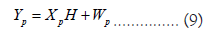
Where H is the channel response, is a known transmission signal, is the received pilot signal, and is the noise vector. Therefore, least-squares (LS) channel estimation can be used to estimate parameter H and minimize the function.
The channel estimation value of the LS algorithm is expressed as Equation (10):
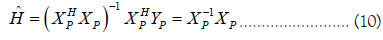
An IFFT operation is performed on the channel estimation value to obtain the estimated channel impulse response [25], as shown in Figure 24.

Figure 24: Channel impact response.
In Figure 24, the presence of multiple pulses indicates the presence of delay extension in the channel. The root-mean-squared delay spread () can be expressed as Equation (11):
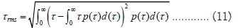
Where  is 0.063 s. It is generally believed that the multipath
fading of the channel follows a negative exponential distribution.
Maximum delay extension (
is 0.063 s. It is generally believed that the multipath
fading of the channel follows a negative exponential distribution.
Maximum delay extension (  ) is four to six times that of f ; therefore is 0.252 s. When designing OFDM signals,
the length of the cyclic prefix should be greater than this delay.
) is four to six times that of f ; therefore is 0.252 s. When designing OFDM signals,
the length of the cyclic prefix should be greater than this delay.
From the above tests, it can be seen that the OFDM signal modulated by 10 Hz QPSK achieves satisfactory penetration performance in outdoor ground-penetrating environments. The influence of ground electric field noise and power-frequency interference noise can be filtered out by FIR filters. The ground channel has an impact on the amplitude and phase of the OFDM subcarriers, which can cause misjudgment of the QPSK demodulation. Using known symbols for channel estimation and equalization can compensate for errors to a certain extent; however, residual bias will remain, and after compensating for residual phase tracking, the rotation effect of the constellation can be restored, enabling the received signal to undergo normal QPSK demodulation.
This article mainly focuses on the principle of ground electrode current field communication, signal design, signal detection, and recognition in the ground electrode current field penetration communication technology. Through reviewing relevant literature and analyzing experimental data, we have reached the following conclusions.
The ground electrode current injection technology has good transmission performance through the ground and can achieve reliable underground communication. Its advantage is that it can still achieve good communication performance in harsh underground road conditions.
Due to the particularity of the geological environment, the earth’s geological channels are very complex, and the attenuation of high-frequency electromagnetic waves is very severe. In system design, only lower frequency (10-20 Hz) waves can be selected for transmission.
Using the minimum frequency shift keying MSK signal as the synchronization head is conducive to achieving signal synchronization detection. Using OFDM signals as transmission signals is beneficial for reducing the impact of time dispersion caused by multipath delay expansion in terrestrial wireless channels on the entire ground penetrating system and eliminating inter symbol interference caused by multipath in terrestrial channels.
The underground engineering underground emergency rescue communication technology is of great significance. Firstly, this technology is widely used and can be applied in scenarios such as tunnels, coal mines, non-coal mines, and large and mediumsized underground engineering. Secondly, the application of this technology can shorten rescue time, achieve scientific and precise rescue, and reduce rescue risks. Once again, this technology can also be applied in fields such as settlement monitoring, geological exploration, and groundwater exploration in underground engineering construction in the future. After years of continuous research, the project team has applied relevant technologies to develop and produce engineering prototypes. The communication frequency used is 10 Hz, and the maximum voltage injected into the grounding electrode is 250 V. The engineering prototype has achieved a maximum transmission distance of 1000 meters and a maximum communication capability of 24 characters of self-generated information length. Based on existing research results and future application needs, we have reason to believe that the grounding electrode current field through ground communication technology will be widely applied and promoted in future research and practice, and contribute to human development.
J.H visualization, data curation, formal analysis, writing—original draft and resources. Z.S supervision and project administration. Z.X conceptualization and validation. Y.Z methodology, funding acquisition and supervision. X.W investigation. X.Z software. All authors have read and agreed to the published version of the manuscript.
This work was supported by the Special Fund for Safe Production of the China Communications Construction Corporation (BC2020000583).
Informed consent was obtained from all subjects involved in the study. The dataset can be accessed upon request.
No conflicts of interest exist in association with the submission of this manuscript. The manuscript has been approved for publication by all authors.
[Crossref] [Google Scholar] [PubMed]
Citation: He J, Su Z, Xu Z, Zha Y, Wen X, Zhou X (2023) Signal Design, Detection, and Identification Technology for Ground-Penetrating Communication Based on Ground Electrode Current Field. Int J Adv Technol. 14:235.
Received: 18-May-2023, Manuscript No. IJOAT-23-24244; Editor assigned: 19-May-2023, Pre QC No. IJOAT-23-24244 (PQ); Reviewed: 02-Jun-2023, QC No. IJOAT-23-24244; Revised: 09-Jun-2023, Manuscript No. IJOAT-23-24244 (R); Published: 16-Jun-2023 , DOI: 10.35248/0976-4860.23.14.235
Copyright: © 2023 He J, et al. This is an open-access article distributed under the terms of the Creative Commons Attribution License, which permits unrestricted use, distribution, and reproduction in any medium, provided the original author and source are credited.