Journal of Geology & Geophysics
Open Access
ISSN: 2381-8719
ISSN: 2381-8719
Research Article - (2014) Volume 3, Issue 5
The hour at hand calls for rapid innovation and drastic introduction of new technology to minimize problems in Oil and Gas Industry and to meet the growing need for Petroleum in all parts of the world. “Oil Well Logging” or the practice of making a detailed record (a well log) of the geologic formations penetrated by a borehole is an important practice in the Oil and Gas industry. Although a lot of research has been undertaken in this field, some basic limitations still exist. One of the main arenas or venues where plethora of problems arises is in logistically challenged areas. Accessibility and availability of efficient manpower, resources and technology is very time consuming, restricted and often costly in these areas. So, in this regard, the main challenge is to decrease the Non Productive Time (NPT) and Huge Mechanical Requirements involved in the conventional logging process. The thought for the solution to this problem has given rise to a revolutionary concept called the “Robotic Logging Technology”. Robotic logging technology promises the advent of successful logging in all kinds of wells and trajectories. It consists of a wireless logging tool controlled from the surface. This eliminates the need for the logging truck to be summoned which in turn saves precious rig time and in turn also reduces Bulk Mechanical Requirements by introduction of Robotics and Automation in the Oil Well Logging Technology. The robotic logging tool here, is designed such that it can move inside the well by different proposed mechanisms and models listed in the full paper as TYPE A, TYPE B and TYPE C. These types are classified on the basis of their operational technology, movement and conditions/wells in which the tool is to be used. Thus, depending on subsurface conditions, energy sources available and convenience the TYPE of Robotic model will be selected.
Keywords: Robotic logging technology, Innovation
Oil field technology has come a long way from Edwin Drake’s first well in 1857, the evolution of Rotary Steerable Systems with which we can drill almost any kind of well profile imaginable. But, as demands continue to skyrocket along with increasing population, newer technologies are required at the earnest to combat hydra headed challenges, difficult subsurface conditions and in the long run decrease Non Productive Time for maximum economic return. Hence, a quest for innovative technology and research is significant from the prospect of optimum production and development of oil and gas fields.
Present Logging Technologies: A brief overview
The Birth of logging: Conrad and Marcel Schlumberger, who founded Schlumberger Limited in 1926, are considered the inventors of electric well logging. Conrad developed the Schlumberger array, which was a technique for prospecting for metal ore deposits, and the brothers adopted that surface technique to subsurface applications. On September 5, 1927, a crew working for Schlumberger lowered an electric sonde or tool down a well in Pechelbronn, Alsace, France creating the first well log. In modern terms, the first log was a resistivity log that could be described as 3.5-meter upside-down lateral log.
Present logging technology: From the early logs used above to LWD (Logging While Drilling) technology used today, logging industry has seen revolutionary changes. Following technologies demand special reference here.
Wireline logging: The oil and gas industry uses wire line logging to obtain a continuous record of a formation’s rock properties. These can then be used to infer further properties, such as hydrocarbon saturation and formation pressure, and to make further drilling and production decisions. Wire line logging is performed by lowering a ‘logging tool’ on the end of a wireline into an oil well (or borehole) and recording petro physical properties using a variety of sensors. Logging tools developed over the year’s measure the electrical, acoustic, radioactive, electromagnetic, nuclear magnetic resonance, and other properties of the rocks and their contained fluids. For this article, they are broadly broken down by the main property that they respond to.
Pipe conveyed logging: Pipe-conveyed logging (PCL) system enables acquisition of real-time, high quality log data in difficult, highly deviated, or horizontal wells where logging tools cannot be lowered into the zone of interest by gravity or because there are adverse well conditions [1]. This system uses drill pipe to convey the tools to the required logging depth. The PCL system mechanically connects the logging assembly to the end of the drill string, using specially designed crossover called a down hole wet connector (DWC). The entire assembly is tripped into the hole until the logging tools reach the upper-most interval to be logged. A side-entry sub (SES) is made up to the drill pipe, allowing the wireline and up hole pump down wetconnect (PWC) spear to be lowered or pumped through the drill pipe and latched onto the down hole assembly. Logging occurs when the tubular string is tripped out of the hole and a continuous log is recorded in real time. The SES is now lowered into open hole to prevent potential damage to the wire line. The SES can be made up at different positions in the tubular string to log other intervals in the well in case of long horizontal sections.
Tractor in horizontal wells: The Well Tractor uses these drive/ wheel sections to push the passenger tool down hole as cable is fed off the electric line unit. When the tractor is initially powered, the wheels in each drive section are deployed out of the tools body. The wheels start to rotate automatically and each wheel using its own independent hydraulic motor facilitates the forward motion. Progress is monitored by tension readings in the e-line unit. When the tractor has been rigged up over the well at the end of the electric wireline, it descends into the hole in a controlled manner. Due to gravity, it falls freely under the control of the wireline until the deviation of the well reaches a point where friction on the tool string and cable prevents the string from progressing any further. At this point, the tractor is activated. The action of initiating the tool centralizes it in the wellbore. Once the wheels establish contact with the casing, the tractor starts to move forward. Upon reaching the desired depth, the tractor is disengaged and conventional logging or perforating operations can resume [1].
Robotic logging technology- breaking barriers: Robotic logging technology promises the advent of successful logging in all kinds of wells and trajectories. It consists of a wireless logging tool controlled from the surface.
Prototype testing experiment
• Filled little metre long tube with brine
• Prototype robotic logging device is used which can be moved by remote control from outside the tube. (Wellhead in case of oilfield)
• Single detector used for size optimization
• Successful movement of the device found
• Log data stored in battery operated memory chip encapsulated in the device (Figure 1)
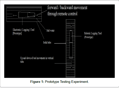
Figure 1: Prototype Testing Experiment.
Advantages over conventional logging techniques
• Reduction in Non Productive time
• Lesser energy requirements
• Very fast action as compared to all other forms of logging
• Can perform well in all kinds of well trajectories
Limitations
• Not tested in field. Still in experimental phase.
• Technology not yet perfected.
Applications (In Cased Hole logs): Since open hole logging involves numerous complex situations and issues we have discussed here the use of robotic logging technology in cased hole logs only. After this technology can be incorporated in cased holes on industrial basis, we can move on to open hole logs.
Logs used: Depends on the requirements of the operator/well. Almost all cased hole logs can be used. Cased hole logging includes conventional GR, Neutron, Casing Collar Locator(CCL),CBL-VDL, CHFR(Cased hole formation resistivity), CHFD(Cased hole formation density), CHFN(Cased hole formation neutron), RST(Reservoir saturation tool), CAST(Circumferential acoustic scanning tool), MIT(Multi fingers imaging tool) etc. We have to understand tool principle, power requirement, source-detectors spacing, tool centralization, generation of radioactive signal through cyclotron in case of density and neutron logging etc.
Method used
It is of following types
TYPE A: This paper mainly deals with this technology. Here robotic logging tool is designed such that movement of the tool is by taking the support of the inner wall of the casing. This is obtained by attaching any one of the following –
✔ Roller bearings
✔ A mini conveyor belt (miniature version of the ones used in tanks)
✔ A chain system (like used in metallic watches)
The methods mentioned above will allow smooth movement of tool along casing wall and will enhance flexibility of the tool whenever casing diameter changes or at joints between two casings. This type is particularly useful in long horizontal sections where the tool can move forward along the track just like a toy robotic car moves along a plane surface because the factor of gravity comes into play (Figure 2). The tool maybe attached to the casing and when the casing is lowered the tool goes down hole along with it. Or it may be lowered down later also, as per requirement, which is actually true for most operations. Further action and working of the tool is monitored from the controlling assembly at surface. Real time information is obtained from sub-surface just like in LWD.
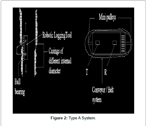
Figure 2: Type A System.
Limitations: In holes where production is being done with the help of tubing, one problem is lowering of the tool to points/depths where spacing between casing and tubing is small. This is because the tool may not enter or get stuck. In such situation the tubing has to be raised to some height to allow the tool to go deeper. This is easy in case of freely suspended tubing. But, will pose a problem if the tubing is fixed with a packer. Solutions to this problem are being worked on Figure 3 and 4.
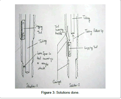
Figure 3: Solutions done.
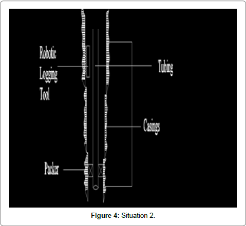
Figure 4: Situation 2.
TYPE B: Here tool is freely suspended in the cased well and controlled completely from surface. Here advantage is that since the tool is placed at central axis of well the radius of investigation is uniformly spread around the well as compared to TYPE A, where tool is close to one particular wall (Figure 5).
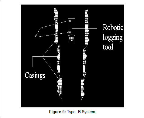
Figure 5: Type- B System.
TYPE C: This is a combination tool of types A and B and can be suspended freely or attached to casing. Depending on the well profile and subsurface conditions it may be used.
Tool design and parameters
For TYPE A: 2 DC Motors used to control the movement. The AT89C51 Microprocessor (MP) is used for tool movement and direction control. This Microcontroller (or Microprocessor) is connected to a peripheral circuit which activates it. Hence this peripheral circuit acts as the Power on Reset circuit.
An obstacle detector sensor is used. This sensor’s output goes to the ports of MP which processes the information and gives necessary command. For example if tool is moving forward and there is formation/ obstacle ahead, this is sensed by obstacle detection sensor, which sends electrical signal to MP which in turn gives command to motors to turn right or left and hence tool movement continues unscathed.
Challenge- Horizontal movement of tool is easy as mentioned before. But vertical movement may be difficult as gravitational force is continually pulling the tool downwards. The solution may be worked out by maintaining an attractive/magnetic force between the metallic casing and the tool.
For TYPE B: Almost similar as TYPE A, but some enhancements may be required. The final tool may be similar to a very miniaturized version of a submarine. The only difference will be that the driver will be replaced by a Microprocessor which will be controlled/directed from the surface by remote control system.
Advantages of Technology
• Reduction in Non Productive time
• Lesser energy requirements
• Very fast action as compared to all other forms of logging
• Can perform well in all kinds of well trajectories (vertical/ horizontal/inclined)
Limitations
1. May lead to permanent loss of logging tool if planning is not proper.
2. Not tested in high pressure, high temperature conditions.
Challenges
1. Whether should be used in all wells or selective wells.
2. Signal type/frequency to be used and their compatibility with different types of drilling fluid/mud [1-6].
This concept is fully innovative and hence if implemented in field may provide with drastic and revolutionary results. We hope at least some part of this concept/technology comes into practical use in the near future and thus help in contributing even a little piece to the massive and ever increasing world of Petroleum.
Our heartfelt thanks goes to Mr. H.S. Maity, Chief Geophysicist (wells), Oil and Natural Gas Corporation Limited. (ONGC), Dehradun. Our special acknowledgement goes to Dr. Subrata Borgohain Gogoi, Associate Professor and Head, Dept. of Petroleum Technology, Dibrugarh University for providing us with tremendous guidance and encouragement in the preparation of the full paper. We owe a debt of gratitude towards the International Conference on Reservoir Surveillance and Management (ICRSM) committee for providing us with an opportunity to present our innovative concepts and ideas on a global forum. Our most sincere thanks to Mr. Xia Yu and Shaanxi Petroleum Society and Xi’an Shiyou University for inspiration and guidance throughout the preparation of this paper. We extend our gratefulness to Dibrugarh University for giving us a chance to express our thoughts and ideas for the greater benefit of the student society at a large. We express our thankfulness to all the DUIET faculty members especially Prof. Prasun Banik and Prof. Haraprasad Mondal for their tremendous support and guidance to us during this entire project.