Journal of Geology & Geophysics
Open Access
ISSN: 2381-8719
ISSN: 2381-8719
Short Communication - (2022)Volume 11, Issue 4
The developed Electro-Impulse Unit (EIU) has a unique and novelty in the technical solution for use in the arrangement of drilling-injection piles (EDT piles). The EIU unit makes it possible to manufacture high-capacity EDT piles. Due to the presence of a high-energy storage tank with a switch connected to the EIU accumulated energy emitter discharge, it is an original electrical design. It is a unique high-performance unit for high-capacity piles as well as base cementing. The device, having no analogs abroad, found wide use in geotechnical construction for erecting EDT piles in pile fields, fencing of foundation beds, cementing of bases, etc. Ensuring reliable operation of the underground part of buildings and structures erected under complex geotechnical conditions is a very urgent task of modern geotechnical construction. In such non-standard construction conditions, the most acceptable buried structures are drilling piles constructed using the currently existing geotechnical technologies.
Electro-Impulse Unit (EIU); EDT pile; Pulse-current generator
The technology of arrangement of drilling-injection piles developed by the authors of the article [1] is widely implemented in the practice of erecting underground structures and artificial bases for industrial and civil use. The technical solution under consideration, being unique for the buried structures, provides the task of creating conditions for safe and reliable operation of drilling-injection EDT piles when using the electric pulse unit. The main achievement of the developed device is increase of device operation reliability and electrical safety during construction of auger piles in pile fields, fencing of foundation beds, soil anchors, and at cementation of bases. During its operation, the operating voltage of the drive is reduced to activate the emitter of the bit-pulse installation.
The possibility of achieving this result is the presence of a discharge electropulse device in the device. It includes a high-energy capacitive drive with a switch. It's connected to the arrester. The additional initiating electrode is located in the gap and is connected via another switch to a low-power high-voltage source. The two apparatuses are connected in series via a synchronization unit. The device is capable of simultaneously operating the switches. The capacitive storage device of the electropulse device is manufactured in a low- voltage design and is connected to the emitter with the aid of a low- voltage cable. The algorithm of operation of the electropulse plant is the following technological sequence (Figure 1).

Figure 1: Electropulse plant for manufacturing of a pile, where: 1-initiating electrode, 2-discharge formation area, 3-ready-to-use injection boring, 4-charging and rectifying device, 5-electrical energy storage, 6-storage switch, 7-low-voltage power cable, 8-charging and rectifying device, 9-low-power high-voltage source, 10-low-power high-voltage source switch, 11-timing unit, 12-cable, 13-electrode, 14-discharge formation area, 15-formed part of the EDT pile (RIT, FORST, ERST).
The pre-produced drill hole (1) is filled with fine-grained concrete (2) and a mounted armature frame, and then the emitter (3) with a low-voltage supply cable (7) is submerged. It is connected to a capacitive energy storage device of a 5-Discharge Pulse Installation (DPI). The electrical energy accumulator (5) is charged to a low voltage of the order of 1000 V with an energy capacity of about 20-50 kJ. At the same time, a low-power high-voltage source (9) is charged to a voltage of 5-15 kV from a charging and rectifying device (8). Then, a series of synchronous pulses of the storage drives (5,9) is fed via cables (7,12) from switches (6,10) to a discharger (3) and an additional initiating electrode (13). The synchronicity of the actuation of switches 6 and 10 is ensured by virtue of a synchronisation unit 11. A series of low-voltage discharges of a basic capacitive energy store (5) is produced by means of breaking the initiating discharge of the capacitive energy store (9) through an electrode (13) in the area of generating an electrical discharge (14) of the discharger (3). Furthermore, only the simultaneous supply of a series of pulses from the storage devices 5 and 9 to the discharger 3 leads to the breakdown of the discharge gap. Said invention makes it possible to produce electrohydraulic impacts acting on the fine-grained concrete (2) and the well wall soil (1), thereby increasing the diameter thereof, compacting a hardening material (2) and forming a part of a pile (15).
When low voltage is supplied, as the voltage in the range of up to 1000 V [2,3], to the arrester 3, an electrical breakdown will not occur, as the voltage levels are not sufficient to close the gap even if there is pseudo conducting medium between the discharger electrodes in the form of "contamination" [1,4]. It is known that in terms of energy release in the electrohydraulic effect, the distance between the electrodes must be in the order of 10-20 mm along the surface of the dielectric. The high voltage of the ignition pulse is also safe, since the energy of its order 200-2000 J is small, and the pulse is short-lived. The device makes it possible to obtain positive results at a relatively low cost, to substantially improve safety conditions and operational reliability, since the claimed device makes it possible to operate reliably in safe modes and, as a result, is provided with drill-and-injection piles having increased load capacity. The inventive electropulse device is widely used for drilling injection piles. It is especially effective for geotechnical construction in cramped conditions [5-9]. Figure 2 shows the actual installation assembled in a five-ton container (Figure 3).

Figure 2: Discharge-pulse unit: 1-pulse-current generator; 2-battery of impulse capacitors; 3-niche for 10 kVA transformer.

Figure 3: Containers with discharging and pulse units inside.
With the help of EIU it is possible to create an auxiliary load- bearing drilling-injection EDT pile Fd. The following algorithm defines Fd (Table 1 and Figure 4).
| No. | EGE | Layer thickness, m | γ1, kN/m3 | с1, kPa |
φl, deg. |
Еl, MPa | IL, unit fraction |
hi, m |
zi, m |
fi, kPa |
fi hi, kN/m |
|---|---|---|---|---|---|---|---|---|---|---|---|
| 1 | Clay loam |
4,5 | 18,0 | 11,0 | 12,0 | 6,0 | 0,6 | 2,0 | 3,0 | 12 | 36,0 |
| 2,5 | 5,3 | 16 | 40,0 | ||||||||
| 2 | 4,6 | 0,3 | 2,0 | 7,5 | 43 | 86,0 | |||||
| 2,6 | 9,8 | 46 | 120,0 | ||||||||
| 3 | Fine medium density sands | 6,9 | 18,6 | – | 29,0 | 26,0 | – | 2,0 | 12,1 | 48 | 96,0 |
| 2,0 | 14,1 | 50 | 100,0 | ||||||||
| 1,9 | 16,0 | 51 | 97,0 |
Table 1: To calculate the load-bearing capacity of an drilling-injection EDT pile with multi-seat ground widths.

Figure 4: Diagram to determine the bearing capacity of a drilling-injection EDT pile taking into account «thrust bearings».
The definition of the bearing capacity of piles with multi-dimensional extensions is different from those on other sidewalks. For example, in SP 24.13330-2011 «Pile Foundations», in determining the bearing capacity of Fd hanging piles, it is assumed that the inclusion of soil in the joint work with piles under the lower end and on the side surface of piles manifests simultaneously. On the proposed method, an «off-point» pile-on» is called into question.
First, the side surface of the piles above the first «thrust bearing» is activated, and then a base bearing capacity of «thrust bearing» is realized. Electric equipment safety and technical operation regulations. Approved by the Order of the Ministry of Energy of the Russian Federation No. 6 dated 13.01.2003. Then the side surface on the next «thrust bearing», which is immediately included in the work, etc., until the «thrust bearing».
Here is an algorithm to determine the bearing capacity of an EDT pile with many-on-sides.
1. The length of the pile, the "under-foot" marks and the diameter of the extensions Ä ku shall be determined on the geotechnical section (Figure 2).
2. The bearing capacity of the EDT pile on the side surface is calculated:
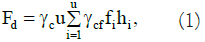
Where –side-surface design resistance; –thickness of i-th layer; γc и γcf –Coefficients of operating conditions of SP 24.13330-2011.
3. The external vertical compressing load shall be defined at the mark of each expansion:
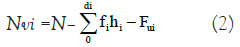
and external moment in eccentricity er, equivalence angle δ, Coefficients Nγ; Nq; Nc depending on φI and δ.
4. The vertical component of the ultimate resistance force is added together with the resistance force on the side surface. Therefore, the bearing capacity of the pile at each elevation of the «thrust bearing» is determined by the formula given below (Figure 5):
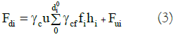

Figure 5: Diagram of vertical tie-in of «thrust bearings» to determine the soil bearing capacity Fd.
5. A minimum value Fdi shall be taken as the design load capacity of the EDT pile.
The type of foundation is influenced by the magnitude of the load from the superstructure and the nature of the subsoil. Any foundation's role is to support and transfer the load from the superstructure to the ground in a safe manner. When lateral loads are applied to weak soil, a pile foundation is preferred. For the first time, the developed electro-impulse unit was widely implemented in geotechnical practice during construction of drilling-injection piles in pile fields, fencing of foundation beds, soil anchors, as well as during cementation of soil bases. Its use makes it possible to significantly facilitate work in geotechnical construction, as well as to expand the possibilities of developing areas previously considered unsuitable for construction.
Citation: Sokolov NS (2022) Pulse-Current Generator for Drilling-Injection EDT Pile. J Geol Geophys. 11: 1030.
Received: 13-May-2022, Manuscript No. JGG-22-17622; Editor assigned: 16-May-2022, Pre QC No. JGG-22-17622 (PQ); Reviewed: 30-May-2022, QC No. JGG-22-17622; Revised: 06-Jun-2022, Manuscript No. JGG-22-17622 (R); Published: 15-Jun-2022 , DOI: 10.35248/2381-8719.22.11.1030
Copyright: © 2022 Sokolov NS. This is an open-access article distributed under the terms of the Creative Commons Attribution License, which permits unrestricted use, distribution, and reproduction in any medium, provided the original author and source are credited.