Journal of Geology & Geophysics
Open Access
ISSN: 2381-8719
ISSN: 2381-8719
Research Article - (2022)Volume 11, Issue 4
Using water injection or gas injection, this study examines the effectiveness of technologies for developing oil rims on gas fields. Considering the need for advanced development of the oil rims within a short period of time, reservoir simulation methods using horizontal wells have been used to rationally develop oil rims. It was confirmed that large volumes of gas must be injected to maximize oil recovery. This happens when gas breakthroughs from the gas cap into the bottom of the production well and from the injection well into the gas section. A cycle process was discovered when gas injection led to the development of an oil rim. The condensate from the gas was taken out, and the dryer gas was then injected back into the reservoir. Condensate concentrations in the gas, especially those near the oil rim, are a major factor contributing to the interest in the proposed concept.
Gas injection; Water injection; Oil rim; Reservoir simulation; Oil recovery
This work aims to analyze the effectiveness of technologies for the development of oil rims on gas fields through water injection or gas injection. Various technologies and systems are available for the development of oil and gas deposits in various parts of the world as well as on the domestic level [1-5], showing the complexity of the problem at hand and the need for a tailored approach when developing each individual deposit. Problems arise primarily caused by the peculiarities of the coexistence of oil, water, and gas in a single hydrodynamic system, as well as a great number of factors that affect the development efficiency of oil and gas deposits. These factors primarily include the ratio of oil and gas reserves, the reservoir properties of productive formations, the physicochemical properties of fluids and the activity of the natural water drive system [6-9]. Obviously, indicators such as raw material prices, tax policies governing the oil industry, etc. are very important.
According to many studies [10-14], the simultaneous and advanced development of a gas cap leads to a rapid disintegration of the oil rim and, consequently, to irretrievable oil losses. On the other hand, the long-term development of the oil rim results in the conservation of gas reserves and a decline in the economic indicators of field development. Considering the need for advanced development of the oil rims within a short period of time, reservoir simulation methods using horizontal wells can be used to rationally develop oil rims. The use of horizontal wells makes it possible to develop with fewer drawdowns and repressions, thereby creating less favourable conditions for the breakthrough of gas and water to the bottoms of production wells [15-19]. This development technology is the subject of research in this paper.
Identifying the problem and describing the model
In order to assess the efficiency of oil recovery by injecting water or gas into the oil rim, it is proposed to solve a two-dimensional, three-phase flow profile problem. The area subject to consideration is an element of the development of the oil rim (Figure 1). The development element consists of half (along the axis) of the horizontal section of the production well and half of the horizontal section of the injection wells. It is considered that the boundaries of the area occupied by the development element are impenetrable. The oil rim is located under the gas cap, underlain by an aquifer from below.

Figure 1: Schematic placement of 8 development elements on a fragment of the deposit. Note:  Formation fluid flow direction,
  the horizontal borehole of production well,
  the horizontal borehole of an injection well
It is more feasible to solve a 2D problem than to use a 3D model because of the following reasons:
1) As the problem dimensions increases, conditions for convergence of the calculation scheme and the accuracy of the results deteriorate;
2) The length of the horizontal wellbore exceeds the distance between the wells (a>b), therefore, in most of the development element, the flow in the direction perpendicular to the vertical plane is negligible.
To ensure high accuracy in solving the problem (task) posed, it is proposed to use implicit difference schemes and fine (detailed) grids.
For the task to be solved, the following assumptions must be met.
1. In the model, there is underlying water. The lower boundary of the water zone is impermeable. It is important to take into account the presence of underlying water in the process under discussion, since the activity of Natural Water-driven Systems (NWS) is manifested to a minor extent under conditions of water or gas injection into injection wells. It is worth noting, however, that identifying NWS activity in oil and gas fields is a separate issue.
2. The vertical boundaries of the area are impermeable, except for the nodes that coincide with the positions of the wells, in which the modes of their operation are set. It is believed that fluids do not flow between development elements and wells equally affect the development elements they are part of [20-22]. No interference is taken into account since the main focus is on modelling the process occurring between the injection and production horizontal wells.
3. Modelling a massive gas cap allows taking into account the ratio of oil and gas reserves in the reservoir and the elastic energy reserve of the gas part, which strongly affects the development of the oil rim. Considering the low viscosity of natural gas and the rapid equilibration of pressure in the gas during the development process for real deposits, the placement of a gas cap above the oil layer makes sense in the model.
4. The construction of the model is based on linear flow according to Darcy's law [23,24]. In addition, relative phase permeability, permeability distribution and anisotropy of the formation, pressure dependences of formation permeability and fluid viscosity are taken into account. Neither capillary pressures nor solubility of phases in each other nor gravitational forces are considered. The last two assumptions are justified by the fact that, firstly, the release of gas from oil and the precipitation of condensate from gas at low drawdowns, where production wells are operated, are insignificant and, secondly, when developing thin oil rims of low-permeability reservoirs, the influence of gravitational forces is not significant [16,25].
According to the continuity equation, the i-th phase has the following form [26,27]:
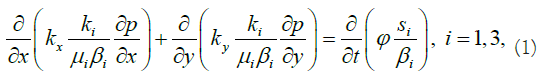
Where water, gas, and oil are represented by 1, 2, and 3; x and y indicate horizontal and vertical axes; p=f (x, y, t) is the field pressure desired with time (t). Kx, Ky - distribution of absolute permeability depending on pressure; ki=f(si) is the relative phase permeability; μi, βi=f(p) are the dependences of viscosity and the volumetric coefficient on pressure, respectively; Φ is porosity; si is phase saturation.
After a series of transformations, taking into account

We obtain a differential equation of parabolic type
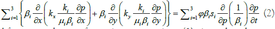
After several transformations, equation (1) is reduced to a hyperbolic form
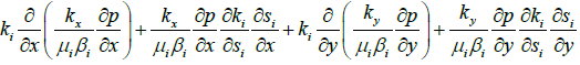
The equations (2) and (3) with their closing relations are a system of partial differential equations describing a three-phase flow in two dimensions. The equations are solved numerically under given initial and boundary conditions.
In this work, “implicit schemes” of time approximation are used for both the parabolic pressure equation and hyperbolic saturation equations (Figure 2).The algorithm for calculating the pressure and saturation fields on a new time layer is based on an iterative process (Figure 3), in which first the parabolic equations are solved for pressure, using the saturation fields known from the previous step, and then hyperbolic equations for saturation are solved using the obtained pressure.

Figure 2: Implicit schemes for approximating equations: (a) in terms of pressure; (b) by saturation.

Figure 3: Scheme of the algorithm.
Following this, the resulting saturation distribution is used to refine the pressure field in the next iteration, and so on. The iterative process continues until the exit condition from iterations is met. At the same time, the nonlinear and quasi-linear terms of the system equations are refined with each iteration. The algorithm described allows accurate results to be obtained.
"Implicit schemes" are the only way to solve the system of equations describing flowing in the reservoir on fine grids.
Due to the strict requirement for a time step in fine grids, "explicit schemes", often used to model entire fields, do not fit the task at hand. The iterative method of solving equations is essential since the first iteration gives a poor approximation to the solution on fine grids, and the more iterations, the more accurate the result becomes. An algorithm was developed to automatically select the time step, allowing the number of time layers in the entire development phase to be kept to a minimum. This reduces the negative effect of error accumulation.
In order to solve the problem (task at hand), a Matlab program was created that can simulate the displacement of oil from the oil rim by injecting water or gas for given dependencies of viscosity, permeability, volumetric coefficient on pressure, phase permeability on saturation, initial data, initial and boundary conditions.
The initial data for the numerical simulation
As an example, let us consider the cases of oil displacement by water and oil displacement by gas under identical conditions and analyze the results. The tasks were solved for the following conditions: L=100 m distance between wells, ho=25 m oil rim thickness, hg=50 m gas cap thickness, hw=25 m water cushion thickness, kx=0.1 μm2 horizontal formation permeability, ka=ky/ kx=0.1 anisotropy coefficient, μo=2 mPas oil viscosity, μw=1 mPas water viscosity, μg=0.1 mPas gas viscosity, βo=1 is the oil volume factor, βw=1 is the water volume factor, βg=105/p is the gas volume factor, rw=0.1 m is the radius of the wells made according to the nature of the opening, the wells are located in the middle between the WOC and the GOC. Dependences of phase permeability are taken from the example given in [28], the graphs of which are given in Figure 4:
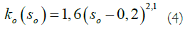
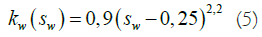
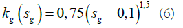

Figure 4: Dynamics of indicators for the development element.
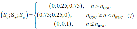
Initial conditions: рi=10 MPa initial formation pressure. Saturation distribution:
Boundary conditions: (Pwf)p=9.6 MPa bottom hole pressure in
the production well, (Pwf)in=10.4 MPa bottom hole pressure in the
injection well,  -impermeable boundary condition, (Sw)in=0.8
water saturation in the injection well when water is injected. The
problem was solved on a uniform grid with dimensions MN=101 ×
11 nodes (n), where M and N are the number of nodes along the y
and x axes, respectively. The pressure in the node and the pressure
in the well are related by the relationships given in [29].
-impermeable boundary condition, (Sw)in=0.8
water saturation in the injection well when water is injected. The
problem was solved on a uniform grid with dimensions MN=101 ×
11 nodes (n), where M and N are the number of nodes along the y
and x axes, respectively. The pressure in the node and the pressure
in the well are related by the relationships given in [29].
Simulation results of water injection
The calculations resulted in a graph in which the oil recovery factor
RFo and gas recovery factor RFg are plotted against  which is the ratio of the volume of water injected to the initial volume of
oil in the element (Figure 5).
which is the ratio of the volume of water injected to the initial volume of
oil in the element (Figure 5).

Figure 5: Dependence of oil and gas recovery on the injected volume of water.
The high gas recovery coefficient achieved during the development of the oil rim is due to the small ratio of the volume of the gas and oil parts. In this example, the ratio is 2, but it often exceeds 20 in real oil and gas fields. For real fields, with a significant predominance of gas reserves over oil reserves, the inevitable gas extraction during the development of the oil rim will not lead to a significant decrease in pressure in the gas cap, only a small part of the gas reserves will be developed. The dynamics of changes in oil flow rates qo, gas flow rates qg, and water flow rates qw at reservoir conditions, as well as the volume of water injection (qw)in for the development element are shown in Figure 4. It is important to note that one production well works with two development elements.
Therefore, for a real well, the indicators will be twice as high as those given. In this case, the length of the horizontal wellbore is 500 m. The calculation results show that water flooding as an artificial reservoir stimulation method makes it possible for the main oil reserves in the oil rim to be involved in development, which would be impossible under natural circumstances. As a result of water flooding, there are inevitable processes of coning formation, migration of oil into the gas and water parts of the reservoir, which leads to the disintegration of the oil rim, and inevitable oil losses in the process.
Oil is "smeared" over the reservoir by the water, which outpaces the oil and mixes with the gas. As a result, water flooding of the gas part is observed, which, of course, negatively impacts the gas recovery factor. Gas reserves have been negatively affected by the oil rim development process with water flooding, and this issue needs to be addressed separately. Despite the fact that the proposed technology has a number of negative aspects, waterflooding may be a rational and applicable way of modifying the reservoir for oil rim development in oil and gas condensate deposits.
Results of the gas injection simulation
Using similar initial conditions, the results of gas injection
simulations are presented below. The gas saturation in the injection
well is equal to (Sg)in=0.55. Based on the computations performed, Figure 6 depicts the graph of the dependence of oil recovery RFo on  which is the ratio between the volume of gas injected under
reservoir conditions, and the initial volume of oil in the reservoir.
The dynamics of changes in the flow rates of oil qo, gas qg and water
qw, adjusted to reservoir conditions, as well as the volume of gas
injection (qg)in for the development element are shown in Figure 7.
The length of the horizontal wellbore is chosen to be 500 m.
which is the ratio between the volume of gas injected under
reservoir conditions, and the initial volume of oil in the reservoir.
The dynamics of changes in the flow rates of oil qo, gas qg and water
qw, adjusted to reservoir conditions, as well as the volume of gas
injection (qg)in for the development element are shown in Figure 7.
The length of the horizontal wellbore is chosen to be 500 m.

Figure 6: Dependence of oil recovery on the injected volume of gas.

Figure 7: The dynamics of indicators of the development element.
The effect of oil rim thickness on oil recovery
Through the use of a program developed within the framework of this study for simulating the displacement of oil from the oil rim, it is possible to assess the influence of various factors on technological development indicators. Let us consider the effect of oil rim thickness on oil recovery in the case of using water as a displacing agent.
It is obvious that the greater the thickness of the oil rim ho, the lower the anisotropy coefficient ka=ky/kx, and the shorter the distance between horizontal wells L, the higher the recovery factor. For example, let ho=25 m, L=100 m, ka=0.1. Then, when water is injected into the oil rim, the recovery factor is 38% (for pumping water in the amount of one pore volume) and 44% (for pumping water in the amount of two pore volumes).
In this section, let's examine the influence of the dimensionless parameter ε=ho/L on the oil recovery in the element. The following are the results of several numerical experiments. The given task was solved for various L∈{80, 100, 120, 140, 180, 220 m}, i.e. for the following values ε ∈{0.31; 0.25; 0.21; 0.18; 0.14; 0.11}. All other dependencies and initial data are taken from the previous case. The graphs in Figure 8 show the dependence of the oil recovery factor on the ratio of the accumulated volume of water injection to the initial volume of oil ρ for various values of ε.

Figure 8: Dependence of oil recovery factor on injected water volume for formation with anisotropy ka=0.1 for different values of ε: 1-0.31; 2-0.25; 3-0.21; 4-0.18; 5-0.14; 6-0.11.
At ρ =1, Figure 9 shows the dependence of the oil recovery factor on ε.

Figure 9: Shows the dependence of the Recovery Factor (RF) on ε at ρ=1.
The results of calculations show that gas injection, as an artificial method of reservoir stimulation, facilitates the development of the main oil rim reserves. As with water injection, inevitable processes are observed during the process of gas injection: oil migration into gas and water zones, breakthrough of the displacing agent into gas and water regions, and formation of water and gas cones. The gas injection case is characterized by large volumes of gas production and injection. To achieve high oil recovery factors, it is necessary to inject large volumes of gas. The gas injection case involves large volumes of gas being produced and injected. In order to achieve high oil recovery rates, large volumes of gas must be injected. This happens when gas breakthroughs from the gas cap into the bottom of the production well and from the injection well into the gas section. This confirms that the development of an oil rim through gas injection enables a cycle process to be employed when condensate is taken from the produced gas, and the dried gas is then re-injected into the reservoir. It is the high concentration of condensate in the gas, especially in the area near the oil rim that contributes to the interest in the proposed technology. The combined processes of oil production from the rim and gas condensate require a separate, more detailed study.
Thus, the conducted studies give grounds to believe that the development of oil rims of gas and gas condensate fields using horizontal wells and reservoir pressure maintenance systems can be profitable, which is supported by high oil prices and the steady improvement of horizontal drilling.
Citation: Hofmann M, AL-Obaidi SH, Chang WJ (2022) Modelling the Development of Oil Rim Using Water and Gas Injection. J Geol Geophys. 11:1028.
Received: 06-May-2022, Manuscript No. JGG-22-17347; Editor assigned: 09-May-2022, Pre QC No. JGG-22-17347 (PQ); Reviewed: 23-May-2022, QC No. JGG-22-17347; Revised: 30-May-2022, Manuscript No. JGG-22-17347 (R); Published: 07-Jun-2022 , DOI: 10.35248/2381-8719.22.11.1028
Copyright: © 2022 Hofmann M, et al. This is an open-access article distributed under the terms of the Creative Commons Attribution License, which permits unrestricted use, distribution, and reproduction in any medium, provided the original author and source are credited.