Journal of Chemical Engineering & Process Technology
Open Access
ISSN: 2157-7048
ISSN: 2157-7048
Research Article - (2019)Volume 10, Issue 2
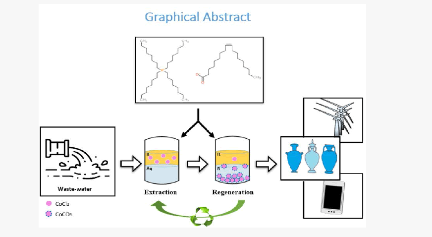
Using the ionic liquid [P8888 +][Oleate-], liquid-liquid extraction has been studied to recover Co2+ from water. Extractionregeneration experiments were followed during five consecutive cycles with Na2CO3(aq) as regeneration solution. Over 99% of Co2+ was extracted and using 0.7-1 M Na2CO3(aq) the extracted Co2+ was recovered for 99% in the form of CoCO3(s). Co2+ transfer shifted from ion-pair extraction in the first cycle to ion-exchange in the successive cycles. Thus, the measurement of a single extraction–regeneration cycle is not sufficient to perceive conclusive information about the steady-state conditions of the process. In the context of the feasibility of the technology, four key aspects are addressed: extraction efficiency, recovery of the IL, loss of the IL, and the end product.
Synopsis
Cobalt extraction from aqueous using ionic liquid [P8888 +][oleate-] and cobalt recovery applying Na2CO3 solution as an efficient and sustainable regeneration strategy since it provides interesting end product for market with high regeneration efficiency.
Cobalt (Co2+ ); Extraction; Hydrophobic ionic liquid; Tetra(octyl)phosphonium oleate [P8888 +][oleate-]
Heavy metal pollution has become a serious environmental threat [1]. Arsenic, cobalt, copper, lead, nickel and zinc are all pollutants that are toxic in nature and can be carcinogenic upon their accumulation in living organisms [2]. Industrial wastewater treatment aims to remove these metals and reduce the level of pollution. Additionally, the process of treatment also allows recovering these metals from waste streams. Refining the process of reclaiming metals from waste water plays an important role in establishing a functioning circular economy, especially in the current context of diminishing metal reserves worldwide [3]. As an example, this study focusses on cobalt, a metal involved in many industrial applications, ranging from aircraft engines, rechargeable batteries, paints, coatings and catalysts. The annual growth in cobalt demand is expected to increase by more than 6% in 2020 [3]. Apart from the industrial need for cobalt, from the experimental point of view, the reason to use cobalt in the present study is its distinctive sharp color in both the aqueous and the organic phase. Its distinct color makes it possible to observe the transfer of cobalt from one phase to the other during the extraction and regeneration phase.
There is a variety of currently existing technologies to remove heavy metal ions from waste water streams such as chemical precipitation, adsorption, membrane filtration and electrochemical methods [4,5]. However, the majority of these techniques come with certain limitations such as high capital and operational costs, poor effectiveness at low metal concentrations, and the production of large amounts of sludge [4]. Liquid-liquid extraction (LLX) is one of the most widely used separation techniques for metal recovery, as both capital and operational costs are relatively low [6-8]. However, the main disadvantage of LLX is the reliance of the use of toxic, flammable, water-miscible, volatile organic solvents (VOCs) such as gasoline, benzene, formaldehyde, toluene, chloroform and tetrachloroethylenes [8]. In order to improve the sustainability of the LLX process, hydrophobic ionic liquids (HILs) can be used instead since they offer an alternative using non-volatile extractants [9].
HILs are organic salts that consist of an organic cation and an organic/inorganic anion [10-12]. These salts are liquid at temperatures below 100°C, have negligible vapor pressure, high thermal and chemical stability, relatively low water solubility, and are good solvents for many organic and inorganic materials [13,14]. Furthermore, Furthermore, their properties can be fine-tuned through selecting several cations and anions, making it a designer solvent [15].
1) High extraction efficiency
2) The use of a cheap regeneration agent/method that ensures the full regeneration of the IL, also implying
3) No loss of IL
4) Obtaining a commercially interesting Co2+ product.
Even though the use of IL’s for metal recovery has been reported previously, to the best of our knowledge the present study is the first one in addressing the combination of all above-mentioned aspects. As illustration, Table 1 lists published studies with some of the aspects categorized. In fact, with almost no identified metal product, Table 1 reflects the common practice that the design of the process starts with the extraction part and the recovery of the IL, instead of defining the regeneration product. We consider the latter approach to be the better option. Therefore, we started out with identifying CoCO3(s) as valuable product and accordingly designed the process in backward direction. Figure 1 schematically outlines the proposed process. In the extraction step, Co2+ is taken up by the IL and in the regeneration (IL recovery) it is back extracted from the IL and simultaneously precipitated as Na2CO3(aq). The labeling of the streams in Figure 1 is used throughout the entire paper.

Figure 1: Conceptual outline of the process discussed in the present study.
| Ionic Liquid | Metal Ions | Regeneration Solution | Recovery IL | Loss of IL in Raffinate** | Identified End Product | Extraction Mechanism | Ref |
|---|---|---|---|---|---|---|---|
| [Bmim]-[Cl] | Ce3+, Eu3+, Y3+ | 0.05 M HNO3 7.0 g/L acetohydroxamic acid+1.0 M guanidine carbonate 0.05 M diethylenetriamine pentaacetic acid+1.0 M guanidine carbonate 0.05 ethylenediamine tetraacetic acid+1.0 M guanidine carbonate 0.1 M citric acid+0.4 formic acid+0.4 M hydrazine hydrate 500 mM [Bmim][Cl] |
Yes | NDA* | NDA | Cation exchange M3+ ßà 3 [Bmim+] |
[19] |
| Cyphos® IL 101 | Co2+, Ni2+ | Water | Yes | 40-80 ppm of [P+] | NDA | Anion exchange MCl42- ßà 2[Cl-] |
[20] |
| CTMA TMA | Cd2+,, Cu2+,, Pb2+, | Mixture of acetone and ethylic alcohol | Yes | 2 wt.%** | NDA | Anion exchange 3M2++2Y2- ßà 2[H+] |
[11] |
| [P44414][Cl]–NaCl–H2O | Co2+,, Ni2+, | NDA | NDA | <0.2 wt.% | NDA | Anion exchange MCl42- ßà 2[Cl-] |
[21] |
| [P66614][Cl] | Co2+,, Ni2+, | 5 steps stripping: 1 x 6 M HCl, 3 x pure water and, 1 x ammonia | Yes | NDA | NDA | Dissolution of metal oxides | [22] |
| [C4mim][Tf2N] | Co2+,, Ni2+, | Nitric and sulfuric acid solution | Yes | 1.40 wt.% | NDA | NDA | [23] |
| [Hbet][Tf2N] | Co2+,, Ni2+, | Hydrogen bis(trifluoromethylsulfonyl)imide HCl |
Yes | NDA | NDA | NDA | [25] |
| [N1888][C4SAc] [N1888][C5SAc] [N1888][C6SAc] [N1888][BnSAc] [P1888][C4SAc] [P1888][C5SAc] [P1888][C6SAc] [P1888][BnSAc] |
Co2+,, Ni2+, | HNO3 HCl |
Yes | 0.3-1.2 wt.% | NDA | NDA | [24] |
| Aliquat-336 | Co2+,, Ni2+, | 1 M HCl 1 M HNO3 1 M HClO4 1 M Na2CO3 0.05 M thiourea + 0.1 M HCl |
Yes | NDA | Yes, solution of metal thiourea | NDA | [27] |
| [C6mim][DEHP] [C6mpyr][DEHP] [N4444][DEHP] |
Co2+,, Ni2+, | HNO3 | Yes | NDA | NDA | Ion exchange Nd3+ßà 3[H+] |
[10] |
| [A336][NO3] | Co2+,, Ni2+, | Milli-Q water | Yes | NDA | NDA | Hydrated anionic complex | [26] |
| C4mimNTf2 | Co2+,, Ni2+, | HNO3 | Yes | NDA | NDA | NDA | [28] |
*NDA: No Data available
**Ref (22) shows weight loss percentage of the applied amount of IL’s during extraction while others indicate the weight percentage of IL present in the aqueous phase.
Table 1: Overview of publications on metal extraction using ionic liquids.
The majority of previous studies show that strong acids and strong bases are able to remove a wide variety of metal ions from a loaded ionic liquid [10,11,18-28]. However, the main drawback of these regeneration solutions is that they do not allow direct re-use of the ionic liquid because strong acids protonate ionic liquids and strong bases form emulsions [18]. In the context of the above mentioned four process criteria, strong acids and bases are often used to merely investigate the extraction process on a lab-scale without considering the consequences for the overall process.
For this study, [P8888 +][Oleate-] was selected for Co2+ extraction because it 1) consists of a natural hydrophobic anion and a hydrophobic cation which is assumed to minimize the losses to the aqueous phases, 2) has the ability to selectively extract transition, rare earth, alkaline earth and alkaline metals depending on the pH and composition of the feed [18], and 3) has a relatively low viscosity at room temperature (200 mPa.s) thus eliminating either the need of a hydrophobic solvent to dilute the IL [29,30] and the need for high(er) temperatures during operation.
In earlier studies, using phosphonium and ammonium-based ionic liquids with the same functionalized anion oleate, sodium oxalate was used as a regeneration solution in both cyclic and continuous experiments. The regeneration efficiency was below 25% in the cyclic experiments (5 cycles) and below 80% in continuous mode (180 minutes) [9,18]. Huang et al. also used sodium oxalate for the regeneration of their acid-base coupling bifunctional ionic liquid, applied for rare earth element separation [31]. Even though the metal regeneration efficiency was higher than in the studies of Parmentier et al., [18] it took at least two days to reach a regeneration efficiency of 90-100% [31]. In the present contribution, Na2CO3 has been used instead of sodium oxalate as it is more environmentally friendly, more than ten times cheaper and results directly in the formation of a marketable product (i.e., CoCO3(s)), which is mainly used as a catalyst and in ceramic pigments. In contrast, cobalt oxalate needs to be calcined to cobalt oxide first before it becomes a commercially attractive product suitable for industrial applications. This calcination process requires high temperatures and produces large amounts of greenhouse gasses, notably CO2. In case cobalt oxide is the desired end product, calcining CoCO3 produces half the amount of CO2 compared to oxalate. The aim of this study was to extract and recover cobalt from industrial wastewater. Extraction-regeneration experiments were followed during five consecutive cycles using [P8888 +][Oleate-] for extraction and Na2CO3(aq) for regeneration. Further, this study will help understand the extraction mechanism of the recovery process. To the best of our knowledge the aforementioned combination of tetra(octyl)phophonium oleate and sodium carbonate as a regeneration solution producing solid CoCO3 has not been reported at present. In order to define the steady-state conditions, the system was investigated by running 5 subsequent extraction - regeneration cycles.
Chemicals and reagents
All the chemicals utilized in this project were of analytical grade and used as purchased. These chemicals are tetra(octyl)phosphonium bromide (>95%, Iolitec), oleic acid (90%, rest polyunsaturates <7%, unsponifiable <0.2% and water <0.05%, Alfa Aeser), cobalt(II) chloride hexahydrate (99%, Sigma–Aldrich), sodium hydroxide (≥ 97%, VWR), sodium chloride (100%, VWR), calcium chloride (Across Organics), and sodium carbonate anhydrous (100%, VWR). Throughout the synthesis, extraction and regeneration experiments, Milli Q-water (≥ 18.2 M cm) was used.
Ionic liquid synthesis procedure
Tetraoctylphosphonium oleate was synthesized according to the procedure previously reported, albeit with some modifications [9]. At first, 0.319 mol (12.74 g) of NaOH was dissolved in 800 ml Milli-Q water before adding 0.231 mol (65.24 g) oleic acid. Then the mixture was stirred (650 rpm) at 45°C for 3 hours. After that, 0.177 mol (100 g) of [P8888 +][Br-] was added to the mixture to be stirred for 8 h at 75°C. Following Parmentier et al. [9], an excess of oleic acid was applied to shift the equilibrium towards IL formation. The IL was washed nine times with, in total, 9 L of Milli Q-water using a separatory funnel in order to remove the impurities such as bromide and sodium. Finally, a rotary evaporator (BUNCHI Rotavapor®R-3) and a vacuum oven at 50°C were used to remove the remaining amount of water. Figure 2 summarizes the synthesis of [P8888 +][Oleate-] The water content of the IL was determined using a 756 Karl Fischer Coulometer. NMR spectra of the synthesized product identified pureP8888 +][Oleate-] IL possessing an excess of 20% oleate (results not shown), all in line with Parmentier et al. [9].

Figure 2: Schematic representation of the synthesis of the ionic liquid [P8888 +][Oleate-].
Analysis of ion and IL concentrations
The concentrations of the metal cations in the aqueous phases (raffinates of extraction and regeneration) and lean IL were determined with Induced Coupled Plasma (ICP) of Perkin Elmer, equipped with an Optima 5300 DV optical atom emission spectrometer (OES). Anion and sodium concentrations were measured using a Metrohom 761 Compact ion chromatograph (IC). In order to analyze the metal concentration of the IL, prior to the use of ICP, microwave-assisted peroxide (H2O2) digestion of the IL was performed using the Ethos Easy advanced microwave digestion system. To that end, 0.25 g IL was added to 10 ml H2O2 (30%), whereupon the digestion tube was sealed and heated up to 180°C for 220 minutes. Afterwards, before analysis the samples were cooled to a temperature between 25°C and 30°C.
To determine the loss of IL to the aqueous phase the P-content and organic C-content of the raffinate were measured using ICP and Total Organic Carbon Analyzer TOC.
The CoCO3 deposit was analyzed using Raman Spectrometry (Horiba Jobin Yvon LabRAM HR Raman spectrometer), Scanning electron microscopy (SEM) and energy dispersion X-ray (EDX).
Experimental procedures
Feed solutions were prepared with a concentration of 1 g/L Co2+ and 1 g/L ` from their corresponding Cl- salts unless otherwise stated. For the first extraction cycle, 5 ml of this solution was added to 5 ml of water-saturated [P8888 +][Oleate-] (water content around 10 wt.%) and mixed at room temperature for 2 hours using a Heidolph Multi Reax vortex mixer at a speed of 2500 rpm. For the first 3 cycles the volume ratio was unity while for the 4th and 5th cycle the ratio changed because the volume of the ionic liquid decreased to less than 2.5 ml due to sample-taking for analysis. Table S1 shows the volumes of feed (Vf,I), regeneration solutions (VRF,i) and IL (VIL) used in the subsequent cycles. In order to account for the variable volume ratio during consecutive cycles, all ion concentration calculations have been corrected (normalized) by multiplying the measured Co2+ concentration in the IL phase by VIL/Vaq (see SI for details). This is possible since in all cases almost full extraction (>99%) of the Co2+ was obtained. Therefore, a lower VIL/Vaq ratio would not lower the extraction efficiency. Prior to the experiments described here, a separate test applying different contact times revealed that 2 hours are more than sufficient to reach equilibrium (actually, more recent tests showed that even 10 minutes would have been enough). To enhance the phase separation, the mixture was then centrifuged using an Allegra X-12 R Centrifuge (Beckman Coulter) at a speed of 3750 rpm for 20 minutes.
After each extraction the HIL loaded with Co2+ was regenerated using different concentrations of Na2CO3 (i.e., 0.3, 0.5, 0.7 and 1.0 M), following the same analytical procedures that were applied for the extraction. From that point, the (partly) regenerated IL was exposed to fresh feed solution for the next extraction cycles. This procedure was repeated for five complete subsequent cycles of extraction and regeneration.
Calculation of efficiencies and productivity
The aqueous solutions after extraction and regeneration as well as the lean IL were analyzed for Co2+. The extraction efficiency (ηE) is defined as the percentage of Co2+ that is removed from the feed, calculated and expressed for cycle i as:
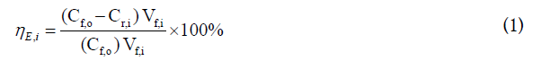
Where,
Cf,o: Co2+ concentration in the feed, [g/L]
Cr,i: Co2+ concentration in the raffinate - cycle i, [g/L]
Vf,i: Volume of the feed - cycle i, [L]
Note that this expression assumes equal volumes of feed and raffinate which is realistic since the IL is pre-saturated with water.
The regeneration efficiency (ηR) is defined as the percentage of Co2+ that is removed from the IL, calculated and expressed for cycle i as:
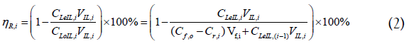
Where,
CLeIL,i: Co2+concentration in the lean IL - cycle i, [g/L]
CLeIL,i-1: Co2+concentration in the lean IL - cycle i-1, [g/L]
CLoIL,i: Co2+ concentration in the loaded IL - cycle i, [g/L]
VIL,i: Volume of IL phase – cycle i, [L]
It is to be noted that for i=1, the value of CLeIL,0 is zero, implying that the experiment starts with a Co2+-free IL.
Additionally, the denominator of the right term of expression 2 is compriseds of two contributions, the first representing the freshly extracted Co2+from the feed, and the second representing the Co2+ residing in the IL already due to the incomplete regeneration during the previous cycle(s).
The recovery of CoCO3(s) (RCoCO3(s),i) is defined as the percentage of the Co2+ extracted that precipates in the consecutive regeneration:
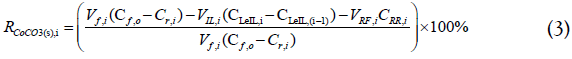
The cumulative recovery R*CoCO3(s),,j), being the amount of Co2+ precipiated over the cycles 1 to j over the amount of Co2+ extracted over these cycles , is given by:

CRR,i: Co2+ concentration in the regeneration raffinate - cycle i, [g/L]
VRF,i: Volume of regeneration feed – cycle i, [L]
Co2+ extraction and regeneration efficiency and recovery
Sodium chloride was added to all feed solutions because it enhances Co extraction. Even though the extraction without NaCl in the feed is already as high as 91%, adding NaCl further improves the efficiency to 99% (Figure 3).

Figure 3:Co2+ extraction efficiency (ηR) using [P8888 +][Oleate-] in the presence and absence of NaCl.
Figure 4 shows the normalized Co2+ concentration during five consecutive cycles of extraction and regeneration, using a 0.5 (A), 0.7 (B) or 1.0 M (C) Na2CO3 solution for regeneration. Panel D shows photographs taken after the first regeneration using different Na2CO3(aq) concentrations with the Co2+ -containing, purplecolored IL phase on top and the solid CoCO3 precipitate collected at the bottom of the tubes. For comparison, the most left test tube contains pure IL. It is clearly visible from the decolorization of the upper phase that a higher Na2CO3(aq)

Figure 4:Normalized Co2+ concentrations in the IL after extraction and regeneration during 5 cycles (CIL,i), using Na2CO3 solutions of either 0.5 M (A), 0.7 M (B) or 1.0 M (C). The SD of the measured Co2+ concentration in the feed is 12 mg/L resulting in a same SD for the calculated Co2+ concentration in the IL of 12 mg/L. Error analysis assuming an error of 2*SD=24 mg/L in the feed concentration and 2.5% in the volume resulted in an error of 5% in the normalized concentration, hence the 5% error bars shown in plots A-C. Panel D shows the first regeneration step at the three different carbonate concentration used.
The composition of the formed precipitate was evaluated using Energy Dispersive X-ray fluorescence spectrometry (EDX). The main component of each composite was cobalt and oxygen with an atomic ratio of 1 to 3, confirming the hypothesis that the precipitate presents indeed CoCO3. The weight percentage (wt %) of Co2+ in the solid product is around 45%, whereas impurities (i.e., sodium and phosphorus) make out less than 1%. This weight percentage is in agreement with commercially available CoCO3 with Co2+ wt% ranging from 43-47% [32]. In addition to EDX, Raman spectroscopy identified the precipitate as well as CoCO3. Details on the analysis of the precipitate can be found in S2.
Figures 5 and 6 show the extraction efficiency (5), the regeneration efficiency (6A), the recovery (6B) and the cumulative recovery of CoCO3(s) (6C), respectively, for the different concentrations of Na2CO3 (and including 0.3 M Na2CO3(aq)). Independent of the cycle number and the concentration of Na2CO3(aq) in the regeneration feed, the extraction efficiency was (nearly) 100% (Figure 5). In contrast, the regeneration efficiency and the (cumulative) recovery did show a dependence on cycle number and/or the concentration of Na2CO3(aq) in the regeneration feed (Figure 6). For all Na2CO3(aq) concentrations, the regeneration efficiency stabilized in the 5th cycle around 96 ± 3%, whereas the recovery of CoCO3(s) stabilized around 99 ± 3%. The cumulative recovery of CoCO3(s) after 5 cycles increased from 91% to 97% when increasing the Na2CO3(aq) concentration from 0.3 to 1 M. The major part of the missing Co2+ is present as based load in the lean IL and lost via the IL samples needed for the analysis of the IL phase.

Figure 5:Average Co2+ extraction efficiency, ηE,i, of P8888 +][Oleate-] over five cycles after regeneration with 0.3 M, 0.5 M, 0.7 M and 1.0 M Na2CO3 solutions. Error percentage is 2 % based on error analysis. Shaded bars for the first three cycles refer to 1:1 IL without excess oleate, using 1 M Na2CO3 as regeneration solution (see also main text).

Figure 6:Average Co2+ extraction efficiency, ?E,i, of P8888 +][Oleate-] over five cycles after regeneration with 0.3 M, 0.5 M, 0.7 M and 1.0 M Na2CO3 solutions. Error percentage is 2 % based on error analysis. Shaded bars for the first three cycles refer to 1:1 IL without excess oleate, using 1 M Na2CO3 as regeneration solution (see also main text).
It was observed (Figures 4A–4C) that upon increasing the Na2CO3(aq) concentration the steady state Co2+ content of the lean (regenerated) IL reduced, e.g. from 150 mg/L to 60 mg/L after increasing Na2CO3(aq) from 0.5 to 1.0 M. The plots of the (normalized) Co2+ concentration in the IL show that when using 1 M Na2CO3(aq) steady-state sets in earlier as compared to when using 0.5 or 0.7 M Na2CO3(aq). The same trend was observed for the regeneration efficiency and the (cumulative) recovery of CoCO3(s) (Figures 6A–6C). For 0.3 M Na2CO3(aq), both the regeneration efficiency and recovery were below 40% in the first cycle showing that under these conditions the IL initially accumulates a significant amount of the extracted Co2+. Note that the fact that the recovery percentage can exceed the 100% level (Figure 6B) is implicit in its definition and a consequence of the Co2+ remaining in the IL due to incomplete regeneration in the previous cycle. In conclusion, these results provide a proof-of-principle regarding the near 100% Co2+ extraction efficiency from the feed, the renderability of the IL, and maintaining high extraction efficiency during the next cycle. If using 1 M Na2CO3, 97% of the Co2+ is recovered rendering CoCO3(s) as end-product. In addition, the mass balance results show that the measurement of a single extraction – regeneration cycle is not sufficient to identify the steady-state of this process as it takes 2 to 4 cycles (depending on the Na2CO3 concentration) to reach an operating point where accumulation effects in the IL can be neglected.
Ion transfer
The majority of previous studies concluded that the extraction of metal ions by ILs is based on a mechanism of ion exchange, a process in which the IL may participate in [11,19-22,33,34]. In order to check whether [P8888 +][Oleate-] demonstrates similar behavior, the transfer of all ion species present between aqueous and organic.
phase was analyzed. Figure 7 shows the absolute amounts (in μmol) of Co2+, Na+, Cl- and [P8888 +] exchanged between the feed and lean IL for the first and second extraction cycles using 0.1 M Na2CO3(aq) during the intermediate regeneration step. The 1st cycle clearly shows a nearly 1:2 molar transfer of Co2+ and Cl- from the feed to the lean IL. This observation indicates that Co2+ extraction is through ion pair uptake, together with Cl-. Importantly, based on the numbers shown in Figure 7A, the charge balance, referenced to the IL phase, is -3 (μmol of elementary charge). Already during the second cycle the transfer process moved into the direction of ion exchange. Here the movement of Co2+ out of the feed into the lean IL was accompanied by the counter movement of Na+ out of the IL into the feed. At steady state, the source of this Na+ is the Na2CO3(aq) used for IL regeneration. As was observed for the 1st cycle, the charge balances for the 2nd cycle are essentially closed as well, independent of the concentration of Na2CO3(aq) during the regeneration step in between (Figures S1-S5). Noteworthy, the charge balance data were based on five independent analyses, i.e., the measurement of the five individual ion species present. Increasing Na2CO3 concentration to 1 M leads to a faster switch of mechanism (in one cycle) as shown in Figures S1- S5. The fact that these balances are (nearly) closed reflects, first, the reliability of these measurements and, secondly, that the possible contribution of other ion species (e.g. H+ and OH-) to the overall charge balance is only minor. For all cases shown in Figures 7 and S5 the pH of the raffinate increased from 5 to 7.9 during extraction. This is partly due to Co2+ extraction next to H+ transfer. A dedicated experiment showed that the pH increased from 5 to 6.2 by only Co2+ transfer. The rest is due to H+ transfer, which is equal to 0.003 μmol H+, an amount that is negligible compared to the total amount of all other ions transferred.

Figure 7:Absolute amount of ion species exchanged (in µmol) between aqueous (CoCl2+NaCl) and organic IL phase during extraction, calculated for the first and second cycle. The intermediate regeneration step was performed with 0.1 M Na2CO3 (aq). Panels a) and b) refer to an IL with (A) and without 20% excess oleate (B).
The observed shift in uptake mechanism, in turn, points to an important conclusion as well. One of the key parameters for process design is the mechanism of, in this case, Co2+ uptake by the IL during steady state. As Figures 7 and S5 show, conclusive information regarding the nature of the uptake mechanism cannot be established by the analysis of merely a single cycle. This is because as long as the system has not yet reached steady state, the uptake mechanism may change. A conceptual design of the process outlined here is discussed in section 4.
As remarked in the section 2.2, the presence of excess oleate during synthesis resulted in a 20% oleate excess in the finally obtained [P8888 +][Oleate-]. To assess the possible role of this excess oleate in terms of the mechanism of Co2+ uptake, the experiments of Figure 7A were repeated but with an IL without oleate excess, i.e., containing 1:1 molar amounts of [P8888 +] and [Oleate-] and using 0.1 M Na2CO3 (Figure 7B). Even though the absolute numbers may slightly differ, the key observation and conclusion remain the same, i.e., a shift from ion pair-like uptake during the 1st cycle towards an ion exchange-like uptake in the 2nd cycle. Also, in this case, charge balances were nearly closed. The extraction efficiency of this 1:1 IL during the two cycles was above 99%, very similar to the values obtained with the IL containing excess oleate (Figure 5). These results justify the conclusion that the presence of 20% excess oleate in the IL does not (significantly) alter its behavior.
Figure 7 also shows another key feature of the system studied here, especially the properties of [P8888 +][Oleate-]. In the 1st and 2nd cycle the amount of [P8888 +] passing to the raffinate was always below 0.3 μmol (=26 mg/L). Compared to the amount of transferred Co2+ (approximately 80 μmol) this is just a very small amount. This observation is in line with TOC analysis, showing a concentration of organics (IL and/or oleate) in the raffinate in the range of 10-50 mg/L.
Conceptual process development
Conceptually, the process consists of an extraction step in which Co2+ is taken up by the HIL and a regeneration step in which it is back extracted from the HIL and simultaneously precipitated by, in this case, Na2CO3(aq). The proposed process does not make much sense for a feed just containing a Co2+-salt, because mixing the feed with solid Na2CO3(s) would have the same result without the need of using the HIL, nor extraction and regeneration devices. The only advantage of extraction - regeneration for this feed would be concentrating the Co2+ which may simplify its precipitation. The proposed process concept seems most applicable for:
• Extraction of a mixture of metals by a non-selective IL and the subsequent precipitation of each metal in a stepwise approach by using different regeneration salts. The advantage is the treatment of IL with the regeneration salt without mixing it with the water feed and avoiding the presence of the salt anions in the extraction raffinate (feed cleaned from Co2+).
• Selective recovery of metals. The HIL used demonstrated selectivity between transition and (earth) alkali metals, though under extreme pH conditions and rather narrow pH windows [20]. Further research is needed to develop more selective HILs that operate under more neutral pH conditions.
Figure 8 schematically presents the conceptual flowsheet of a Co2+ extraction/regeneration process combined with a stream table. The extraction column is fed at the top with wastewater containing cobalt chloride and sodium chloride. The recirculated ionic liquid enters at the bottom of the column and moves as small droplets to the top, while extracting the Co2+ out of solution. It should be stated that this is only one of the operation modes possible, alternatives are the Karr column, Kuhni column or Rotating Disk Column (RDC). It is important for the mixing to not be vigorous to avoid emulsifying the two liquids. This last requirement makes the Karr column an interesting alternative. The Co2+-loaded ionic liquid, due to phase separation collected at the top of the column, is transferred to the regeneration column. Here the IL is contacted (again as small droplets moving up the column) with an aqueous sodium carbonate solution in order to perform the back-extraction of Co2+ and the regeneration of the IL. The Co2+-lean ionic liquid collected at the top of the column is recycled to the extraction column. More recent analysis of the batch extraction experiments showed that a contact time of 5-10 minutes is sufficient to reach equilibrium. By adjusting the droplet size and the operation mode of the extractor, the rise velocity of the droplet can be controlled. In combination with the column height the residence (contact) time can be adjusted. As mentioned above, the LLX column should enable a contact time of at least 10 minutes. The solid CoCO3 will settle at the bottom and leave the column with the water stream. The two-phase separator next in line to the regenerator serves to separate out the solid cobalt carbonate (end-product). In more detail, the methodology applied depends on the properties of the solid (e.g., density, particle size) and can range from a relatively simple gravity separator to a filtration unit or a centrifugal separator. Preliminary experiments showed that the solids settle easily. An effective regeneration process does not require per se the full, 100%, removal of the solids from the regeneration fluid before recycling. The separated sodium carbonate solution is pumped back to the regeneration column. In case of excess water, a purging process is carried out, after which fresh sodium carbonate is added. It is important to note that the IL will also be loaded with some NaCl.

Figure 8:Conceptual flow-sheet for Co2+ recovery from water using the ionic liquid [P8888+][oleate] for extraction and a 1 M Na2CO3 solution for regeneration.
The data presented in the stream table are calculated based on the mol/mass balance for the different components, the distribution coefficient for Co2+ (assumed to be minimal 5, which was confirmed with equilibrium experiments) as well as analysis data for the different ions in the system. Furthermore it is assumed that steady-state is obtained (Co2+ exchanged for 2 Na+), no IL is lost to the water phase (which means no fresh IL needs to be added to the system) and all the water added to the regeneration cycle through the fresh soda leaves during the purge. Charge balance calculations (not added) for the IL phase revealed that not all ions present in the IL were analyzed. The mass balance calculation shows that operating with a Feed to Solvent ratio of 5 (mass based) in the extraction and the regeneration column is possible. This will reduce the flow in each recycle by a factor of 5 (see total of stream S-1, S-4 and S-6 in the stream table) and consequently the equipment size is reduced as well. Regeneration with 1 M Na2CO3 results in a concentration drop to 0.6 M, which is still acceptable for the regeneration efficiency.
Using the hydrophobic ionic liquid [P8888 +][Oleate-], the proof-ofprinciple of a new process for metal ions removal from water has been demonstrated. The extraction efficiency of Co2+ was above 99% and by using Na2CO3(aq) as regeneration solution up to 98% of the initially present Co2+ in the feed was recovered as CoCO3(s), being a marketable product. The proposed process is most interesting for the selective recovery of metals and can accommodate any HIL that shows selectivity, can be regenerated, and has a low loss rate to the aqueous phases. [P8888 +][Oleate-] already shows selectivity, though under extreme pH conditions. Furthermore, it has a low loss rate to the aqueous phases. By performing five extractionregeneration cycles it became evident that the measurement of a single extraction – regeneration cycle is not sufficient to perceive conclusive information about the steady state conditions of the process with respect to efficiencies, recoveries, and ion transfer mechanism. The case discussed in this paper shows the need for multiple subsequent extractions – regeneration cycles as a sound basis for process development.
This work was performed in the cooperation framework of Wetsus, European Centre of Excellence for Sustainable Water Technology (www.wetsus.nl). Wetsus is co-funded by the Dutch Ministry of Economic Affairs and Ministry of Infrastructure and Environment, the European Union Regional Development Fund, the Province of Fryslân, and the Northern Netherlands Provinces. The authors like to thank the participants of the research theme Desalination for the fruitful discussions and their financial support.
Citation: Othman EA, Van der Ham AGJ, Miedema H, Kersten SRA (2019) Ionic Liquid-Based Process Development for Cobalt Recovery from Aqueous Streams. J Chem Eng Process Technol 10: 397. DOI: 10.35248/2157-7048.19.10.397
Received: 25-Jun-2019 Accepted: 12-Aug-2019 Published: 19-Aug-2019 , DOI: 10.35248/2157-7048.19.10.397
Copyright: © 2019 Othman EA, et al. This is an open-access article distributed under the terms of the Creative Commons Attribution License, which permits unrestricted use, distribution, and reproduction in any medium, provided the original author and source are credited.