Journal of Ergonomics
Open Access
ISSN: 2165-7556
ISSN: 2165-7556
Research - (2019)Volume 9, Issue 1
The existing cabins of ground transport-technological machines have large glass surfaces to achieve enhanced visibility. In the warm seasons this leads to an increase in heat penetration due to the solar insolation. This leads to some issues as, on the one hand, operators need increased visibility in their cabins, but on the other hand, the thermal influence of solar insolation on the operator’s body must be reduced. Therefore, it is vital to optimize the thermal energy balance of the microclimate in the cabins of ground transport-technological machines through local thermoregulatory systems. To solve the existing problem, we set the goal of increasing the comfort of the work environment of ground transport-technological machines by optimizing the thermal energy balance of the microclimate. In order to achieve this goal, we set several tasks in the field of theoretical and experimental research to justify the design and operating parameters of a local thermoregulatory device for cabins of ground transport-technological
machines. We theoretically determined the functional dependency connecting the design and operating parameters of the proposed device and identified design constraints. We described the procedure of our experimental research into the process of the formation of a comfortable thermal state for transport-technological machine operators both in standard conditions and under the influence of the developed thermoregulatory device. Experimentally confirmed the relationship between the important design parameters of this device (between the pitch and the diameter of the tubes) for different set values of the process of heat measuring, the temperature of the liquid, the thickness of the package of clothes and the surface temperature of the human operator. The dependences between the indicators of the thermal state of a human operator and the parameters of the proposed thermostatic device are obtained in the form of changes in the specific heat content of a person, which made it possible to optimize the design parameters. As a result of the research, optimal values of the heat flux density (268 W/m²) of the conductive panel of the device were determined taking into account the normative value of the temperature rise of the body temperature of a human operator (2°C per hour), which will ensure comfortable working conditions in the cabin of the mobile machine. The influence of body weight and human growth on the change in the parameter of the power density of the heat flow increases as the rate of increase in body temperature of the human operator increases. With the given limitations of the experiment, the optimal heat flow rate from the surface of the proposed device to the entire body surface of a human operator was revealed, which was 486 W with average values of body weight and height (70 kg and 1.7 m, respectively).
Thermal comfort; Microclimate; Conduction; Thermoregulation; Thermal sensation; Body heat content; Thermal state of the body; Power of the heat flow
The choice of microclimate normalization systems and means is one of the most important areas in determining ways to improve the thermal comfort conditions in the cabins of Transport Technological Machines (TTM) during the cold and warm seasons [1,2]. Currently, there are many types of systems and means for ensuring operator comfort, and classifications for both. This makes it difficult to analyze their applicability in small enclosed spaces, for example, in TTM cabins. The analyzed studies deficit unified classification criteria by which these systems and means could be systematized [3]. They must be systematized to solve a number of organizational and technical problems related to the configuration and use of effective systems and tools. In particular, the use of thermal cabin protection is complicated by the resulting reduced visibility [4]. Cabin ventilation and air-conditioning is restrained as a result of their significant shortcomings, such as high energy consumption, cost, and possible harmful effects on the body [5].
It should be assumed that the "machine" subsystem should provide both technical and psychophysiological safety: there must be comfortable working conditions for the TTM operator which leads to fewer errors [6-8].
The nature and the degree of the decrease in human performance are determined by the thermal state and body heat content [9,10]. The process the formation of Body Thermal Status (BTS) is studied in different spheres and conditions of human activity when solving various scientific and practical problems related to one goal–to improve performance by ensuring thermal comfort for the operator. In a cooling microclimate, reduced performance may be caused by an increase in the weight of clothing. Cold has an adverse effect on the activity of the cardiovascular system, and in case long-term exposure to cold, vegetative dystonia develops, which exacerbates chronic diseases [2]. The influence of heat on the body in the conditions of a warming microclimate also leads to a decrease in the body’s protective forces and reserve capacities [1].
The main methodological approach in studying the process of BTS formation is mathematical modeling and experimental research of the thermal balance of the body [11,12]. This is possible both due to the normalization of microclimate parameters based on studying the thermoregulation mechanism, and the development, comparison, and selection of the most effective technical systems to provide comfortable conditions [13].
The microclimate of TTM cabins has been studied by physiologists, hygienists, physicians, and engineering and technical specialists based on the influence of the microclimate parameters on human BTS [14,15]. There are different approaches to assessing the thermal comfort of the microclimate depending on the different goals of the research being conducted.
The methods for assessing the thermal comfort of the microclimate are developed in three directions:
•Building of temperature scales and indices [3].
•Design of special devices which imitate the body [11,12,16].
•Theoretical analysis of the thermal balance of the body [10,17].
Currently, high-performance cabin air conditioning systems are used to optimize the thermal energy balance of the ground TTM microclimate, but they are expensive and energy-consuming and have moving elements that are not completely reliable under vibration and shock conditions [1-5,10-12].
It is quite challenging to solve all of the issues which would provide thermal comfort to operators in TTM cabins. The artificial microclimate device must meet requirements for design simplicity, low manufacturing cost, serviceability by low-qualified personnel, and safety [4,5,7]. Therefore, the theoretical and experimental justification of an innovative local thermoregulatory device is an urgent research area requiring special consideration.
Thermal comfort is one of the main factors characterizing the conditions of the work environment, health and well-being, the degree of work satisfaction, and performance. It has been proved that there is a high correlation level between the temperature mode and human performance [9,10]. Experimental studies have unequivocally established the negative influence of unfavorable microclimatic conditions on worker performance [17].
When there are no air conditioners or other coolers, the air temperature in TTM cabins can significantly exceed the outside air temperature in the warm season, mainly due to solar radiation [1]. Naturally, microclimate parameters are far from permissible in regions with high and moderately high temperatures during the daytime in the warm season. A partial reduction of the air temperature in the cabin through natural ventilation leads to an increase in the air movement speed and the accumulation of dust in the cabin interior [2]. All research and development projects dealing with the creation and improvement of human thermal comfort systems and means must be carried out with consideration of the current socio-economic, sanitary, and hygienic requirements aimed at ensuring human thermal comfort. In this regard, two directions are defined: the implementation method and the constructive solution [14,15].
Researchers emphasize the parameters of normalizing the microclimate conditions in cabins when studying the thermal comfort of TTM operators. A number of papers deal with the estimation of the thermal load on the TTM cabin due to heat inflows of various origin [1,2]. These studies make it possible to choose the most rational technical solutions in terms of decreasing heat input and reducing the economic and energy costs of air conditioning. The quantitative characteristics of heat inflows into the TTM cabin differ significantly across these papers [1-5,10-12]. The research results demonstrate that the heat input from total radiation through cabin enclosures is 62 ... 79% of the total heat flow, heat release of the engine and transmission-8 ... 15%, hydraulic system and electrical equipment-3 ... 8%, and the operator -10 ... 15%. Therefore, the conductive heat exchange between the operator’s body and contact surfaces and means of ensuring human thermal comfort deserve extensive study.
Based on the theoretical research, we identified the main factors influencing the formation of human BTS. The above considerations allow us to assert that for a comprehensive evaluation of BTS it is necessary to determine:
•The temperature conditions of the operator’s body through measurements of body and skin surface temperature [1,2].
•Thermal sensations based on operator questionnaires [18].
•Microclimate parameters: temperature, humidity, and air mobility [10,17].
Studies in the field of BTS and human thermal sensations affirm that the body temperature (“core” temperature) is largely a reflection of the body's heat content [4,5]. At a temperature of 36.8 ... 37.0°C, an individual in a state of a relative physical rest assesses their thermal sensations as "cold" and "cool", respectively. A temperature of 37.6°C is a sign of a significant overheating of the organism in this case. 38°C is the maximum physiological value in a state of a relative physical rest. The maximum physiological value of cooling is the rectal temperature of 35.8°C.
Scientists have proved that there is a dependency between skin temperature level and thermal environmental conditions, and have determined a close correlation with thermal sensations, which allows us to consider body temperature as one of the most important and informative BTS indicators.
It has been revealed that body heat content is a value derived from the average body temperature and the heat capacity of body tissue. At the same time, heat deficit is a change in this value in relation to comfortable levels. Heat deficit is a positive value if heat transfer exceeds heat generation and is negative if heat generation is higher than heat transfer, i.e., a state of "heat accumulation" begins. Table 1 shows the values of deficit and accumulation of heat corresponding to different thermal sensations.
Table 1: Deficit and accumulation of heat in the body and thermal sensations.
| Thermal sensations | kJ | kcal |
|---|---|---|
| Heat deficit | ||
| Comfortable | up to 121 | 29 |
| Cool | 203 | 50 |
| Cold | 450 | 110 |
| Very cold | 740 | 176 |
| Heat accumulation | ||
| Very hot | 344 | over 80 |
| Hot | up to 344 | up to 80 |
| Warm | up to 208 | up to 50 |
| Comfortable | up to 121 | up to 29 |
Studies of the heat measuring process using an active thermal regulation system assumes control of heat measuring indicators on the sections of the seat surface which the operator comes into contact with [18]. This became possible with the use of a Local Thermoregulatory Device (LTD) that we have developed. It is a heat exchange device which differs from conventional devices by its application conditions, geometry, materials, and location within the contact zone between the operator’s body and the backrest surface and the seat cushion of the TTM cabin [13]. The layout of the LTD elements and nodes is shown in Figure 1.

Figure 1: The scheme of an experimental sample of a local thermoregulatory device: 1–removable cover; 2–cushion; 3–backrest; 4, 5–input and output manifold, respectively; 6–pump; 7–liquid flow regulator; 8–hydraulic accumulator; 9 and 10–flexible tubes; 11, 12, 13, 14–outlet and inlet tubes of the thermal and cooling unit, respectively.
Figure 2, shows a diagram of heat-conducting elements of the LTD in the contact zone. In the first variant (Figure 2a), heat is removed if there is a temporary air gap between the surface of the backrest and the operator. In the second variant (Figure 2b), the heat is removed in the absence of an air gap, i.e., in case of a tight contact between the surface of the seat cushion and the operator [13].

Figure 2a: Diagram of the heat-conducting elements of the device located in the zone of contact between operator and seat; a) when there is an air gap and top.b.>tliq..

Figure 2b: With close contact and top.b.>tliq. (top.b. and tliq. is the temperature of the operator’s body and the liquid (water), respectively (°C), d and S are the diameter and pitch of the tubes (mm), h and h' are the distance from the operator to the center of the heat-conducting tubes and the thickness of the layers of clothing (mm), 1 is the operator, 2 is layers of clothing, 3 is the air gap, 4 is working elements of the device (tube), and 5 is the backrest or seat cushion.
As the figure shows, the pattern of heat flows is rather complicated. In this case, heat is transferred from one surface to the other through thermal conductivity, convection, radiation, and due to mass transfer, i.e., evaporation of moisture from warm surfaces and condensation on cold surfaces. It is necessary to further study heat transfer in the zone of contact between the operator’s body and elements of liquid local thermoregulatory systems.
A specific feature of LTD operation is that the power of its heat flow must be formed with consideration of the excess (or deficit) of heat in the operator’s body expressed by the amount of heat flow from their body to the LTD (or vice versa). The device should adjust the increase or decrease in the average (internal) body temperature by about 2°C in one hour. This speed was established as a given value by taking the standard rate of body temperature decrease into account. The main portion of the heat flow between the surface of the body and thermoregulatory devices analogous to the LTD is attributed to thermal conductivity through clothing and tube walls [13,18].
Since the "operator-cabin" system is complex, poorly organized, and stochastic, theoretical justification of the LTD parameters is not sufficient. Therefore, let us calculate the power of the heat flow of the Conductive Panel (CP)-an LTD module with a contact surface consisting of multiple liquid-filled tubes.
The indicators of CP heat flow power shall be defined as quantities characterizing the required heat measuring per unit of time, primarily the power density of the heat flow from the surface of the body necessary to ensure comfortable thermal sensations and body heat content and the total heat flow power [14,15]. These indicators will also be determined by the parameters of the operator’s body (height and body weight), and comfortable conditions–by the permissible rate of the average body temperature drop.
Since the analytical expressions of all heat fluxes are cumbersome, we restrict ourselves to considering some of the heat balance equations directly on the surface of a human body in its zone of contact with CP (in heating mode) [14,15]:
Qh=Qv.air-cl.-b.+Qliq.-cl.-b. (1)
Where, Qh–thermal content of the human body, Wh·h; Qv.air-cl.-b., Qliq.-cl.-b.–respectively, the heat that is transferred from the ventilated air and the liquid (water) CP through clothing to the human body, Wh·h.
Next, for the heat flux we write:
Рh.b.=Рv.air-cl.-b.+Рliq.-cl.-b. (2)
Where, Рh.b.–heat flow to the human body (W), Рv.air-cl.-b., Рliq.-cl.-b.– respectively, heat fluxes from ventilated air and liquid CP through clothes to the human body (W).
Turning to the average values, equations (1) and (2) can be written as follows:
Рv.air-cl.-b.=αv.air(tv.air – top.b.)FCP (3)
Where, αv.air–average heat transfer coefficient from ventilated air to the human body (W/(m²·°C); tv.air–ventilated air temperature (ºС), FCP–contact area of CP with the surface of the human body (m²),
Рv.air-cl.-b.=kliq.(tliq.–top.b.)Ltot. (4)
Where, kliq.–averaged local coefficient of heat transfer from fluid of CP to the body, referred to the unit length of the tubes (W/m·°C); Ltot.–total length of CP tubes in contact with the body (m).
From the heat balance equation (2) the required amount of heat supplied by the CP coolant will be:
Pliq.-cl.-b.= PCP= Gliq.Cliq.(tliq.in.– tliq.out.) (5)
Where, PCP–heat flux from CP (W), Gliq.–mass flow rate in CP (kg/h), Cliq.–heat capacity of fluid in CP, (Wh·h/(kg·ºC)), tliq.in., tliq.out.–accordingly, the inlet and outlet CP fluid temperature (ºC).
In the balance equations (1) and (2) there is no overheating or overcooling of the human body. In the case of body hypothermia, the left side of equation (2) requires adjustment. It can take the following form:
ΔРh.b.=Сop.Мop.·Δtb.av. /Δτ (6)
Where, ΔРh.b.–shortage of heat flow to the human body, W; Сop.– specific heat of the human body (W·h/(kg·°C)), Мop.–human body weight, kg; Δtb.av. /Δτ–change in the average temperature of the human body as a whole over a certain period of time (°C/h).
Heat transfer in the zone of contact of the human body with CP elements in heating mode requires further study. The analytical solution is hampered by the uncertainty of many of the initial parameters: the distribution of heat release over the surface, the distribution of air flow in the area of the ventilation gap, etc. In assessing the heat transfer from ventilated air to the human body, the greatest difficulties are caused by the determination of the heat transfer coefficient αv.air. At the same time, there is a large amount of experimental data on heat transfer coefficients, which are very diverse in terms of the conditions of the experiments. An attempt to summarize these data in the form of empirical dependencies was made in,where it is assumed that the heat transfer coefficient αv.air at moderate values of ventilation is approximately equal to 5 ... 7 (W/ m²·°C). In our case, this approach is also justified by the fact that, when applying a CP (in heating mode), the main amount of heat is supplied to the body by liquid.
Taking into account formulas (3) and (4), we write equation (2) in expanded form with the indicator ΔРh.b.:
Cop.Cop.·Δtb.av. /Δτ =αv.air(tv.air–top.b.)FCP+Gliq.Cliq.(tliq.in.–tliq.out.) (7)
In equation (6), the quantities such as Cop., Mop., αv.air, FCP, Cliq. within certain limits, we take as constant.
Taking into account the accepted restrictions, equation (7) can be represented as:
а1Δtb.av. /Δτ=а2а3(tv.air–top.b.)+а4Gliq.(tliq.in.–tliq.out.) (8)
Where, а1 … а4–constant coefficients, units.
From equation (8) it follows that it is most efficient to carry out the process of forming the thermal comfort of the operator by changing the temperature parameters of the liquid (tliq.in.) at the entrance to the CP or the flow rate (Gliq.) of the coolant in it.
Many researchers affirm that thermoregulatory devices should
Many researchers affirm that thermoregulatory devices should adjust average (internal) body temperature at a rate of about 2ºC per hour. Let us take this speed as a given or normative rate of body temperature decrease.
The tasks in the study involved obtaining the following dependencies:
• Between the thermal state indicator (or thermal sensation) of the operator and the microclimate parameters in the TTM cabins.
• Changes indicators of the thermal state (body heat content and thermal sensation) of the operator’s body on the LTD parameters and operating conditions.
The main task in planning our experiment was to find the mathematical dependency of the parameters for optimizing the formation of the appropriate thermal state of a TTM operator’s body..
The parameters of the microclimatic conditions in the premises of a small closed volume greatly affect the physiological and psychological state of a person, which is manifested in a particular thermal state of the body. Since the thermal state of the body can be assessed by thermal sensation (Sh) and heat content (Qh), they can also evaluate the parameters and environmental factors, as well as the physiological parameters of the operator [13]. Based on this conclusion, it can be argued that the thermal state is an indicator in which the relationship between the parameters and environmental factors and the corresponding indicators of the thermal content of the human operator is expressed.
The heat sensation index (Sh) characterizes both parameters (temperature, humidity and air speed, surface temperature of fences and seats) and environmental factors (category of gravity of labor and heat-protective properties of clothes). It can be represented as follows [8,13]:
Sh=F1(tair, ϕr.h., ωair, tf.s., Qm., Δcl.) (9)
Where, Sч–thermal sensation of a person (points), F1–functional dependency symbol; tair–air temperature (ºC), ϕair–relative humidity (%), ωair–air speed (m/s), tf.s.–fencing surface temperatur (°C), Qm.–energy expended to perform mechanical work (W), Δcl.–heatproof property of clothes (clo).
The index Qh, characterizing the physiological parameters of the operator (body temperature, skin and rectal temperature, specific heat capacity and human body weight), can be represented as follows:
Qh=F2(top.b., th.sk., tr, Сop., Мop.) (10)
Where, Qh–thermal content of the human body (W·h), F2– functional dependency symbol; top.b.–human body temperature (°C), th.sk.–human skin temperature (°C), tr–rectal body temperature (°C).
From expressions (9) and (10) it can be seen that either the values of the complex of parameters and environmental factors are based on the identified body reactions (heat sensations), or vice versa, the complex of physiological indicators is somehow related to the parameters and environmental factors.
Based on this, we can suggest the following relationship:
Sh ↔ Qh or
F1(tair, ϕr.h., ωair, tf.s., Qm., Δcl.) ↔ F2(top.b., th.sk., tr, Сop., Мop.). (11)
This expression shows that the parameters of the environment and the complex of physiological indicators are related through the indicator of the thermal state of the human body, which is composed of the indicator of thermal sensation (Sh) and heat content (Qh). To characterize the human physiological indicators of heat content, the most informative is the determination of heat content through the weighted average skin temperature.
Thus, on the one hand, the characteristics of thermal sensation and thermal content are interconnected, and on the other, they have a different physical nature, but these characteristics are objective.
So, the power of the heat flow between the CP and the body can be determined by the formula [13-15]:
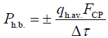
Where, Рh.b.–power of the heat flow between the CP and the body (W), qh.av.–average specific density of the heat flow to the surface of the body (W·h/m2), FCP–area of the CP along its perimeter (m²), and Δτ–time taken to increase or decrease the average body temperature by 2°C (h).
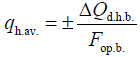
In this case, the average specific density of the heat flow passing through the entire surface of the operator’s skin will be:
In this case, the average specific density of the heat flow passing through the entire surface of the operator’s skin will be:
 (13)
(13)
Where, ΔQd.h.b.–deficit or excess of heat in the operator’s body (W·h), and Fop.b.–surface area of the operator’s body (m²).
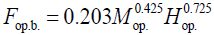
The surface area of the operator’s body can be determined by the Dubois formula:
 (14)
(14)
Where, Мop. – operator’s weight, kg, and Нop.–their height, m.
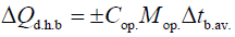
Deficit or excess of heat in the body is determined by the formula:
 (15)
(15)
Where, Cop.–specific heat of the operator’s body equal to 3.47 W·h/(kg·°C), and Δtb.av.–change of the average temperature of the body due to an increase or decrease of heat in the body (°C).
Let us calculate average body temperature (tb.av.), taking into account the values of rectal temperature (tr) and the average weighted skin temperature (ts.av.w.), in light of their mixing coefficients, which reflect the proportion of tissues with a temperature close to the "core" (K) and the "shell" (1-K), according to the equation:
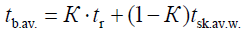 (16)
(16)
Where, tb.av.–average body temperature (°C), tr–rectal temperature of the body (°C), tsk.av.w.–average weighted temperature of the skin (°C), and K–mixing coefficient, which reflect the proportion of tissues with a temperature close to the "core" (K) and the "shell" (1-K).
Let us write equation (1) in expanded form:
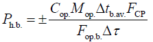 (17)
(17)
In equation (17), the ratio of the value FCP/Fop.b. can be regarded as the coefficient χ, which takes the contact area of the CP and the surface of the operator’s body into account. To this end, this expression can be represented as:
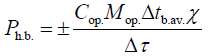 (18)
(18)
Where, χ–a coefficient which takes the contact area of the CP and the surface of the body into account.
The main portion of the heat flow between devices analogous to the CP and the surface of the body is attributed to thermal conductivity through the walls of the CP tubes and clothing. Therefore, the power of the CP heat flow due to the thermal conductivity effect can be determined by the formula:
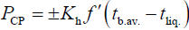 (19)
(19)
Where, PCP–power of the CP heat flow (W), Kh–the coefficient of heat transfer through the liquid, the wall of the tube, and clothing in the zone of contact between the CP tubes and the operator’s body (W/(m2·°C)), f ΄–specific surface area of the CP tubes in contact with one square meter of the body surface (m²), and tliq.– liquid temperature in the tubes (°C).
The specific surface area of the CP tubes contacting the surface of the operator’s body can be determined by the expression:
f = χ f ′ (20)
Where, ƒ–total surface area of the CP tubes contacting one square meter of the surface area of the operator’s body (m²):
f = πd . l (21)
Where, d–outer diameter of the tubes (mm), and l–length of the tubes at the calculated square meter of the body surface (m).
The coefficient of heat transfer through the liquid, the wall of the tubes, and clothing in the zone of contact between the CP tubes and the operator’s body can be determined by the formula:
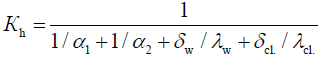 (22)
(22)
Where, α1–coefficient of heat transfer between the wall of the CP tube and the operator’s body (W/(m²·°C)), α2–coefficient of heat transfer between the liquid and the wall of the CP tube, respectively (W/(m²·°C)), δw, δcl. thickness of the CP wall and the operator’s clothing (m²), and λw, λcl.–coefficients of thermal conductivity of the walls of the CP tube and the operator’s clothing, (W/(m·°C)).
The value of α1 can be neglected, since it is many times smaller than the value of α2. We transform the formula (22), taking into account that:
 (23)
(23)
Where, Nu–Nusselt number for a laminar current (flow), λliq.– coefficient of thermal conductivity of the liquid, W/(m·°C), and din.–inner diameter of the CP tube, m.
We obtain the final expression:
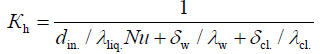 (24)
(24)
After our transformations, expression (19) will be as follows:
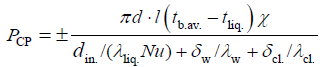 (25)
(25)
Therefore, the total heat flow between the operator’s body and the LTD tubes in the approximate calculations can be estimated by an approximate dependency:
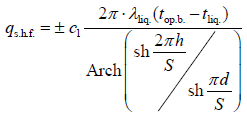 (26)
(26)
Where, qs.h.f.–specific heat flow due to thermal conductivity and mass transfer (power density of the heat flow) (W/m2), с1·– coefficient which takes mass transfer into account, Arch(x) and sh(x)–functions of hyperbolic arccosine and sine (in MathCAD), respectively, and S–pitch of the tubes, mm.
Therefore, we determine the power of the heat flow Ph.f. to the CP (value with a plus sign) surface or from it (value with a minus sign) due to thermal conductivity (W) [13-15]:
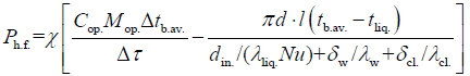 (27)
(27)
Where, Δtb.av./Δτ–change in average body temperature in general over a certain period of time (°C/h).
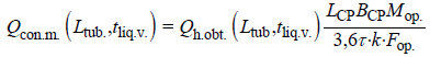
The heat flow Qcon.m., which is removed in the mathematical model with the help of LTD, must correspond to the one taken in the course of the experiments. It can be estimated from the condition of equality of the rate of decrease in the heat content of the organism in accordance with the average normative rate of decline in body temperature [13]:
 (28)
(28)
Where, Qcon.m.–indicator characterizing the conditions of heat measuring (W), Ltub.–variable length of tubes (m), tliq.v.–fluid temperature variable (°C), Qh.obt.–heat content of the human body obtained in the experiment (kJ/kg), LCP–sum of the lengths of the backrest and cushion (the parameter is fixed) (m), BCP–width of the backrest and cushion (the parameter is fixed), (m), Mop.–human body weight (kg), Fop.–surface area of the human body (m2) τ– average standard time of the human body temperature decrease by 1ºC (h), k–coefficient relating the rate of fall in the temperature of the human body with the rate of fall in the heat content of the human body
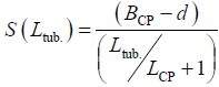
It is also necessary to take into account that the total length of the LTD tubes changed in laboratory experiments discretely (16, 20, 24 m), by disconnecting the corresponding rows of tubes. In this regard, it is necessary to substitute the values of the average pitch of the LTD tubes corresponding to each series of experiments into the equations. For the average pitch of the tubes LTD can be written:
 (29)
(29)
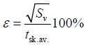
To estimate the discrepancy between the results of laboratory experiments and theoretical models, it is possible to use the rootmean- square error:
 (30)
(30)
Where, tsk.av.–average value of the temperature of the skin surface, obtained by averaging over all experiments and replicates (°C), Sv–mean square deviation of the experimental temperatures of the skin surface from the calculated, that is:
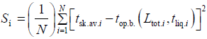 (31)
(31)
Where, N–total number of repetitions for all experiments; i– current repetition number; tsk.av.i–average temperature of the skin surface in the i-th repetition (°C), Ltot.i, tliq.i–accordingly, the total length of the tubes (m) and the temperature of the liquid (°C) for this ith repetition of this experiment.
If we compare the obtained data and study the dynamics of the measured indicators, it is possible to estimate the human BTS with certain confidence and to predict possible changes [16]. Using mathematical modeling methods is one method of estimating and predicting human thermal state under temperature loads [19-21].
All means of normalizing the microclimate conditions must firstly satisfy sanitary and hygienic requirements or conditions for a comfortable thermal state. Therefore, body heat content and thermal sensation were chosen as the optimization criteria which reflect a comfortable BTS in our experiments, as they can be evaluated by through complex assessment of the comfort of microclimate conditions [9,13].
The performance efficiency of the device according to the comfort criteria, taking thermal sensation into account, depends on the operator’s subjective perception of the microclimate conditions. In addition, heat flow power has a dependency on such unpredictable values as the gap between the operator’s body and the CP, the thickness of his clothing, etc. [18]. Therefore, it is necessary to experimentally justify the LTD operating parameters based on the absolute minimum value of the microclimate comfort criteria connected with both the operating parameters (liquid temperature tliq.) and the design parameters (the total length of the tubes Ltot). Then, we formulated the optimization problem and represented it as a system (eqn. 32) wherein the variation intervals of the optimized parameters tliq. and Ltot. were chosen with consideration of the power of the heat flow from expression (eqn 27) [9,13]:
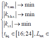 [16;24](32)
Where, kt.sen., kb.h.c.–criteria of a comfortable microclimate from evaluation of thermal sensation and body heat content, respectively, cond. units, ks.t.–coefficient taking the significance of skin temperature into account, cond. units., and Ltot.–total length of the tubes, m.
Through our research, we also justified the operating parameter (density of the heat flow due to heat conduction and mass transfer) and the design parameter (pitch of the tubes at different diameters). In this case, the variation intervals of the optimized parameters were chosen with consideration of the structural schemes of the seats of a particular machine [9,13,18].
We performed experimental studies using experimental design methods to determine rational design parameters and operating modes of the LTD structure under study [13]. At the same time, we determined the scheme and design and operating parameters of the proposed LTD. We obtained dependencies between the required power of the CP heat flow, the temperature of the liquid, liquid flow rate, etc.
Our experimental research method included measuring the parameters of microclimatic conditions of the environment inside and outside the TTM cabins. The operator was questioned about his thermal sensation (for assessing his thermal state) (Appendix A1). In addition, we recorded the date, time, and location of the research, the type of work performed, the operator’s age and clothing, and weather conditions (cloudiness and solar radiation).
Field studies (tests) were conducted in weather conditions typical for the warm and transitional season. The outside air temperature was from 10 to 31°C, the relative air humidity was within a range of 20 ... 80%, the wind speed-0.5 ... 6.0 m/s, the cloudiness did not exceed one - two points. Temperature and relative humidity (outside) ambient air and wind speed were measured at a height of 1.6 ... 1.7 m from the ground and at least 10 m from the car.
The microclimate parameters in the TTM cabins were measured in operation when the engines were loaded by 70% (±15%) of the nominal value.
The study covered groups of 5 to 10 people aged 20 to 40 years who were not adapted to the specific working conditions of the TTM operator, performing a moderate workload, dressed in summer clothes with a thermal resistance of 0.5 ... 0.6 clo (1 clo=0.155 m2·K/W) and familiar with the modified points of thermal sensations characterizing the thermal state.
The duration of the experiment is commensurable with the period of an operator’s work shift; the microclimate parameters in the TTM cabin were measured when the operator gave an evaluation of his thermal sensations.
The microclimate parameters in the TTM cabin were measured at three points: at the feet, at the chest level, and in the breathing zone. The measurements were repeated 25 times.
Laboratory studies were carried out in a climate chamber created within a standard cabin. The climate chamber was equipped with an air-evaporative-type air conditioner and an electric heater, which made it possible to simulate (change) the parameters of microclimatic conditions. To create for a human operator (subject) working conditions of the required degree of severity of labor, he was asked to perform the required number of influences on the control levers in the cabin.
The microclimate parameters in the climate chamber were maintained at a given level with the doors and windows closed throughout the experiment [14,15]. When the air conditioner or heater was on, the air flow should not have been directed to the operator. The parameters of the microclimate in the climate chamber corresponded to the conditions of the warm period of the year and were: air temperature 32 ± 0.5ºC, relative air humidity 40 ... 60% and air velocity 0.2 ... 0.4 m/s. The air temperature was measured at the feet of the operator in the pedal area at a height of 0.1 m from the floor level, and also in the operator's breathing zone at a level of 1.2 m from the floor level. Relative humidity and air velocity were measured in the operator's breathing zone at a height of 1.2 m from the floor level. The temperature of the inner surfaces of the cabin was measured at five points. The survey of operators on their thermal state was carried out simultaneously with measurements of the parameters of the microclimate using a modified scale of thermal sensations (Appendix A1). In addition, thermal sensations were recorded on the same scale, which characterize local comfort or discomfort in the legs, waist, back, neck or body surface, illuminated by direct sunlight.
The parameters and operating modes of the local temperaturecontrolled device were changed according to the experimental design methodology. The volumetric flow rate during the operation of the LTD did not change during the entire period of the experiment and was 118l/h. The inlet temperature of the liquid at its maximum flow through the LTD can be adjusted according to a scheme which involves mixing a portion of the warm liquid leaving the LTD with cold liquid from the heat exchanger. This method of regulation ensures a more uniform liquid temperature in all tubes and zones of the LTD, and consequently, more uniform cooling of the operator’s body than when the conventional regulation of the liquid flow rate is used [13].
Studies were also conducted at different times of the day, while the reading of the measured parameters began no earlier than 30 minutes after the establishment of the microclimate parameters in the climate chamber, specified by the experimental method, and repeated with an interval of 10-15 minutes. During one experiment, the temperature in the cabin changed by no more than 0.5°C, and the temperature of the water in the LTD-by no more than 0.2°C. A group of 5 people took part in the laboratory experimental studies, and they were subject to the same requirements as in the field experimental studies. The weighted average temperature of the skin was determined by indicators of the temperature of human skin, measured at five points on the surface of the skin by means of thermoelectric contact sensors. The temperature of the skin was measured in the forehead, chest, back, leg, thigh and hand [14,15].
The indications of average human body temperature were determined as follows:
–for the comfortable (thermoneutral) zone:
tb.av.=0.7tr + 0.3tsk.av.w (33)
–for the zone of thermal discomfort of the1st degree (tB=25°C):
tb.av.=0.79tr+0.21tsk.av.w. (34)
–for the zone of thermal discomfort of the2nd degree (tair=35 °C):
tb.av.=0.9tr+0.1tsk.av.w. (35)
The weighted average temperature of human skin was determined from the expression:
tsk.av.w.=0.25t1+0.25t2+0.2t3+0.18t4+0.07t5+0.05t6 (36)
Where, t1, t2, t3, t4, t5, t6–respectively, the temperature of the skin, chest, back, leg, thigh, forehead and hand (ºC).
The research results were processed in two stages. The first stage was preliminary processing, which involves screening out gross errors and checking whether the distribution of the measurement results corresponds to the law of normal distribution. The second stage involved choosing models and building the regression dependency of the operator’s thermal sensations on the microclimate parameters in the TTM cabin. Data processing allowed us to build regression dependencies of questionnaire responses on the selected factors, verify of their adequacy, recalculate the responses on comfort criteria value, and analyze the obtained dependencies to seek optimal factor values.
The results of data processing allowed to check the normal distribution of random values of microclimate parameters using criteria. The check was carried out according to several criteria [9,13]. Initially, the distribution of random values of microclimate parameters was checked by the criterion of mean absolute deviations. This test showed that this criterion is satisfied only by the distribution of indications of relative humidity. However, given the large sample size, the test was also performed according to the criterion of the range of variation. According to this criterion, all considered values of microclimate parameters can be considered distributed according to the law of normal distribution. According to the asymmetry coefficient, the relative humidity of the air cannot be considered distributed according to the law of normal distribution. According to the coefficient of kurtosis, all values correspond to the law of normal distribution.
Since the “operator-TTM cabin” system is complex, poorly organized, and stochastic [8], it is not sufficient to justify only the parameters of LTD operation. Through our research, we determined the average specific density of the heat flow passing through the entire surface of the skin; the surface area of the operator’s body according to the Dubois formula; deficit or excess of heat in the body; average body temperature, taking into account the values of rectal temperature and the average skin temperature; coefficient of heat transfer through the liquid, the wall of the tube, and clothing in zone of contact between the CP tubes and the operator’s body; the specific surface area of the CP tubes contacting the surface of the operator’s body; and the total heat flow between the operator’s body and the CP tubes. The diagrams of some experimental dependencies are shown in Figures 2 and 3.

Figure 3: The dependency of the power density of the heat flow qs.h.f. at different distances between the tubes (S) with different diameters (d), 1, 2, and 3 represent tube diameters of 8, 5.6, and 3, respectively (mm).
Analysis of the dependencies allows us to determine the necessary design and operating parameters of the LTD, given the value of either. For example, to provide a comfortable heat flow density of qs.h.f.=268 W/m2, it is necessary for the tubes S to have a pitch in the range of 12.5 ... 17 mm, depending on the versions of the tube diameter d used (Figure 3). Taking into account the criterion of comfort by heat content qop., the optimal value of tube length reaches 23.5 m at a liquid temperature of 20°C (Figure 4). It is not possible to achieve a maximally comfortable state at a higher liquid temperature.

Figure 4: The dependency of the operator’s specific body heat content qop. on the length of the tubes Ltub. at different liquid temperatures tliq.; 1, 2 and 3 represent liquid temperatures of 16°C, 20°C, and 24°C, respectively
Figure 5a shows a diagram of the dependency of the change in the average density of heat flow power at a given rate of temperature decrease on the body weight at different values of operator height. As the figure shows, the dependencies are almost linear. The rate of the change in the average density of heat flow power is approximately 25 W/m² for every 10 kg of increase in body weight. When weight increases, the intensity of the growing average density of the heat flow power decreases to some extent, and this decrease is more pronounced for taller individuals. The range of the change in the average density of the heat flow power was 230-315 W/ m² when body weight changed within the range of 60 ... 90 kg. The diagram of the dependency of the change in the density of the heat flow power on the height of the individual in Figure 5b shows linearly-decreasing curves. The intensity of the decrease in the density of the heat flow power is approximately 25 W/m² for every 0.3 m of increase in the operator’s height.

Figure 5a: Dependency of the power density of the heat flow on the variation of body weight at different heights; 1, 2 and 3 indicates an operator height of 1.85, 1.75, and 1.65 (m), respectively.

Figure 5b: The dependency of the power density of the heat flow on variation in height at different weights; 1, 2 and 3 indicated operator weight of 60, 75, and 90 (kg), respectively.
Analysis of the dependencies has shown that density of the heat flow power increases significantly with a growing rate of body temperature increase (150 W/m² per 1°C of the temperature increase rate) irrespective of the weight or height of the individual. The influence of body weight and height on the change in heat flow power density increases with a growing rate of the operator’s body temperature increase. At the average values of body weight and height (70 kg and 1.7 m), as well as the normative rate of the body temperature increase rate (2ºC per hour), the required average density of the heat flow power is 268 W/m². This will provide the operator comfortable working conditions in the TTM cabin. Using the values of heat flow power density, it is easy to determine the total heat flow to the entire surface of the body necessary to provide a given (comfortable) temperature increase rate by multiplying the heat flow power density by the surface area of the body. Preliminary calculations of the total heat flow power were 486 W at average weight and height.
The comfortable state of a human operator in the cabin of a mobile machine can be fixed only in a very narrow range of changes in air temperature, which is strongly influenced by the temperature of the enclosing surfaces (which is rather difficult to regulate). The effect of air temperature is more pronounced compared to the temperature of the fencing surfaces. Studies have shown that, according to the criterion of heat sensation, discomfort is more likely due to overheating of the body than due to hypothermia. As the temperature of the fencing surfaces increases, the air temperature also shifts to lower temperatures in order to correspond to a comfortable human condition (from 23.5°C to 20°C). Therefore, to achieve a comfortable state of the operator according to the criterion of heat sensation only by changing the air temperature in the cabin is impossible. This confirms the need to use LTD in conditions of heating and cooling microclimate (in order to correct heat sensations when the temperature of fencing surfaces changes) even in the case of using traditional systems for changing the air temperature in the cabin.
We justified a method for regulating heat measuring from the body surface of a TTM operator using the LTC. We theoretically determined the functional dependency connecting design (d, S) and operating (tliq.) parameters of the LTD operation, design constraints (BCP, LCP), as well as the indicator characterizing the working conditions of the operator (ΔQd.h.b.) and the parameters of his comfort level (qop., top.b., h, h'). As a result, for the conditions of heat measuring and heat supply, dependences of the required power of the LTD on the total length of the tubes and the temperature of the liquid were obtained. In addition, the dependences of the change in the average temperature of the surface of human skin on the total length of the tubes LTD and the temperature of the liquid in it. The greatest discrepancy between the theoretical model and laboratory experiments is observed in the region of high liquid temperatures and with average values of the total length of the tubes. Since the experimental values (tsk.av.w.) below theoretical, then in this range of values (Ltub.) and (tliq.v.) there is a more efficient heat measuring from the human body by means of LTD, than theoretically predicted. Apparently, heat transfer begins to manifest itself more clearly due to mass transfer (transfer of capillary moisture). In addition, it is possible that the uneven pitch of the tubes of the LTD is more efficient than the uniform. It should be noted a rather high degree of conformity of theoretical models and results of laboratory experiments, since the mean square relative error of deviation of experimental data from theoretical curves does not exceed 5% (ε=4.924%).
We obtained the equations of the relation between the design parameters of the CP (between the pitch S and the diameter of the tubes d) for various set values of heat measuring, liquid temperature, and the operator’s skin temperature and clothing thickness. We experimentally determined the optimal value of heat flow power density (qs.h.f.).
With the goal of providing the most efficient conditions for the component of the specific heat flow qs.h.f., we determined the required value S of the pitch of the CP tubes (at Ph.f.=100 W, BCP=0.42 m, LCP=0.8 m, top.b.=37°C, tliq.=20°C, h'=1 mm, and d=5.6 mm), which was about 14 mm. The suitable diameter d of the LTD tubes is 5 ... 7 mm. We determined the numerical value of the volumetric flow rate of the liquid through the LTD (at d=5.6 mm, S=14 mm, Ltot.=22.4 m, Ntub.=28 pcs.), which was 118l/h. The value of the pressure drop Htub. on the tubes was 237 Pa.
Heat measuring can be regulated when LTD operating conditions change for rigid design parameters by varying the liquid flow rate and temperature. To this end, it is necessary to further develop a scheme for regulating the liquid temperature in the LTD through mixing to ensure more uniform liquid temperature in all the CP tubes and zones.
In the future, fitting TTM cabins with the LTD will have important advantages over the standard cabin which has only traditional airconditioning or ventilation systems, such as:
• High-quality heat exchange with the surface of the operator’s body (due to a higher coefficient of thermal conductivity when using a liquid heat carrier, for example, water).
• Improved working conditions, saving working time (due to decreased losses resulting from temporary disability), and increased output volume (due to the reduction of unproductive energy costs needed for the operator to overcome unfavorable working conditions).
Citation: Glemba K, Averyanov Y, Gritsenko A (2019) Increasing the Comfort of the Work Environment of Ground Transport-Technological Machines by Optimizing the Thermal Energy Balance of the Microclimate. J Ergonomics 9:245.
Received: 19-Apr-2019 Accepted: 27-May-2019 Published: 03-Jun-2019 , DOI: 10.35248/2165-7556.19.9.245
Copyright: © 2019 Glemba K, et al. This is an open-access article distributed under the terms of the Creative Commons Attribution License, which permits unrestricted use, distribution, and reproduction in any medium, provided the original author and source are credited.