Journal of Geology & Geophysics
Open Access
ISSN: 2381-8719
ISSN: 2381-8719
Research Article - (2016) Volume 5, Issue 6
Geotechnical studies were carried out to investigate the foundation conditions in Igbogene, Etelebou in Bayelsa State, Nigeria. The evaluation was carried out by means of three (3) number boreholes to a maximum depth of 30 m below the existing ground level using the cable percussive rig. Field and laboratory investigations reveal a near surface stratigraphy of clay to an average depth of 6 m underlain by loose silty sand to a depth of 10 m below the existing ground level. Underlying this clay layer, the formation presents a stratum of sand which extends to the maximum depth of investigation. Field and laboratory analysis carried out on relatively undisturbed soil samples of the silty clay showed the undrained shear strength of this near surface soil to lie between 40 and 56 kPa with a mean value of 47 kPa. However, the 1.0 m thick peat embedded between 3.0 m and 4.0 m will great increase the compressibility of this clay. Pile foundation is recommended, considering the anticipated load and the very high compressibility of peat under imposed load. Piles should be straight-shaft, closed-ended steel pipe piles and driven into the medium dense sand. Pile load test should be carried out on all piles to confirm working load and estimated settlements.
Keywords: Borehole, Engineering geology, Foundation, Subsoil, Stratigraphy, Bayelsa state
Site investigations in one form or the other is always required for long tern stability of structures [1]. The knowledge of the geotechnical characteristics is very desirable for design and construction of foundation of civil engineering structures in order to minimize adverse effects and prevention of post construction problems. Civil engineering projects are dedicated to the realization of efficient and economical works in a short time which requires an acceptable risk increasingly low. Geotechnical studies are highly important in such projects. Thus, a good estimate of the risk associated with geotechnical parameters has become a major issue since most of the new structures are located on sites with difficult conditions [2]. Some studies have been carried out on geotechnical properties of the subsoil’s generally [3-5].
The study area (Figure 1) lies in the coastal Niger Delta sedimentary basin. The area is endowed with the sedimentary rocks characteristic of the Niger Delta. The detailed geology of the area has been described by Reyment, Short and Stauble [6,7]. Litho-stratigraphically, the rocks are divided into the oldest Akata Formation (Paleoceone), the Agbada Formation (Eocene) and the youngest Benin Formation (Miocene to Recent). The wells and boreholes tap water from the overlaying Benin Formation (Coastal Plain Sands) (Figure 2). This formation comprises of lacustrine and fluvial deposits whose thicknesses are variable but basically exceeds 1970 m. The Benin Formation has lithologies consisting of sands, silts, gravel and clayey intercalations.
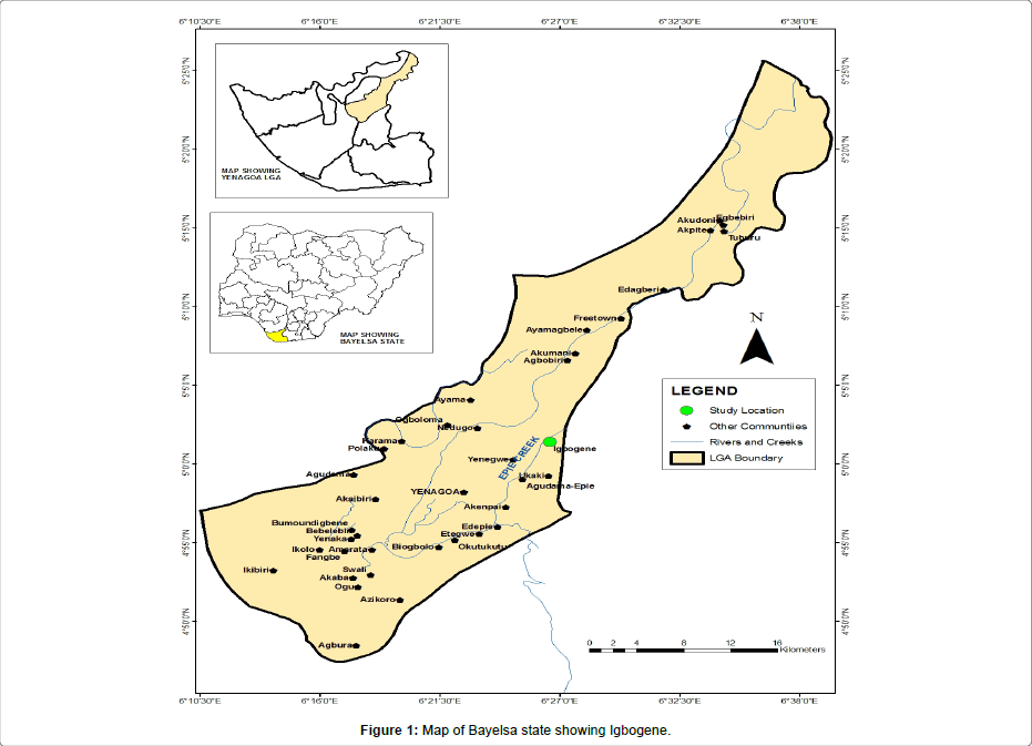
Figure 1: Map of Bayelsa state showing Igbogene.
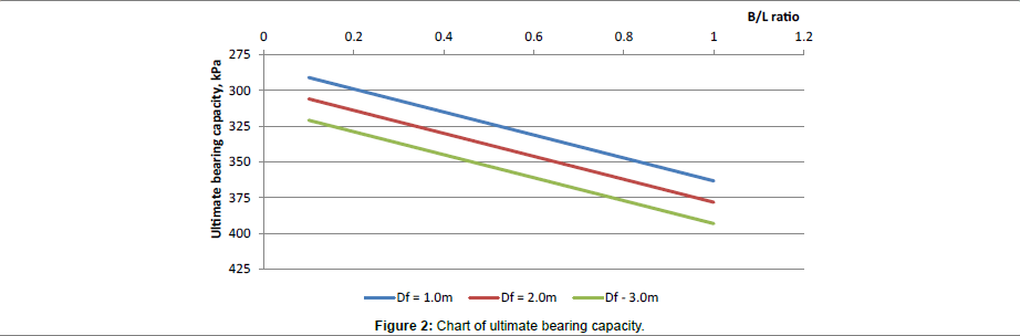
Figure 2: Chart of ultimate bearing capacity.
The area is within the coastal zone. The coastal zone which comprises the beach ridges and mangrove swamps is underlain by an alternating sequence of sand and clay with a high frequency of occurrence of clay within 10 m below the ground surface (Figure 3). Because of the nearness of these compressible clays to th e surface, the influence of imposed loads results to consolidation settlement. The impact of the imposed load is exacerbated by the thickness and consistency of the compressible layer. This, in addition to other intrinsic factors contributes to the failure of civil engineering structures [8,9]. For the purpose of generating relevant geotechnical data inputs for the design and construction of foundations for structures, it is imperative that the area be geo-technically characterized through sub-soil investigation. The interest of this study therefore is to identify, quantify and take into account the physical and mechanical characteristics of soils for a better estimate of the geotechnical risk (settlement and stability), in the area.
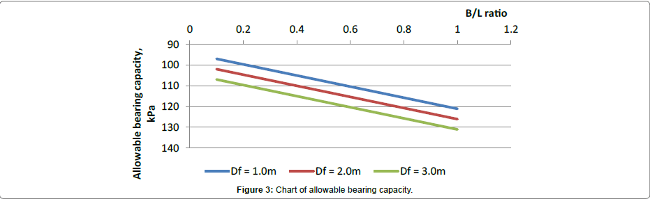
Figure 3: Chart of allowable bearing capacity.
Methods of Investigation
Three (3) geotechnical boreholes with soil sampling and measurement of water table were investigated. The boreholes were advanced using a cable percussion boring rig. All three (3) boreholes were terminated at a depth of 30 m below the existing ground. The boreholes were drilled by the shell and auger cable percussive drilling method, using a hand rig. Detailed laboratory investigations were carried out on representative undisturbed and disturbed samples obtained from the boreholes for the classification tests and other tests (Figure 4). All tests were carried out in accordance with BS1377 [10] – Methods of test for soil for civil engineering purposes. Representative samples were taken at regular intervals of 0.1 m depth, and also when a change in soil type was observed. The samples were used for a detailed and systematic description of the soil in each stratum in terms of its visual and haptic properties and for laboratory analysis. In the cohesive soils, a large number of undisturbed samples were taken for examination and laboratory analysis [11]. Standard Penetration Tests (SPT) was carried out at regular intervals of depth in the granular sediments in order to assess their in situ densities. In this test, the number of blows required to drive the standard sampling spoon 300 m penetration after the initial sitting drive was recorded as the SPT (N) value.
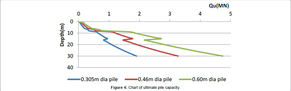
Figure 4: Chart of ultimate pile capacity.
Atterberg consistency limit tests were carried out on the cohesive samples (Figure 5). The particle size distributions of a number of representative samples of the cohesion less soils were determined by sieve analysis [12]. Unconsolidated Undrained triaxial (UU) tests were performed on relatively undisturbed samples obtained from the boreholes. Laboratory consolidated tests were also carried out on relatively undisturbed samples with the aim of determining the compressibility properties of the soils [13].
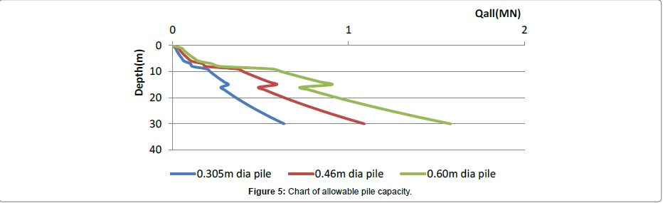
Figure 5: Chart of allowable pile capacity.
Soil properties and stratigraphy
The lithology reveals a near surface clay layer about 6.0 m thick. The silty clay layer overlay a stratum of sand that extends to the final depth of investigation. The loose sand with occasional gravel increases in density to becoming medium dense sand as the borehole advances to the final depth. The results revealed that the samples are low to medium https://www.omicsonline.org/searchresult.php?keyword=plasticity silty clay [14]. The results also disclosed that the samples are predominantly, fine to medium and medium sands. The plot of void ratio (e) against effective pressure (p) for the samples tested, are shown in Table 1, together with calculated values of the coefficients of consolidation (Cv) and of the coefficients of compressibility (Mv). Test results show that the samples are of moderately high compressibility and predominantly exhibiting negligible swelling potentials.
| Parameters | Min | Max | Mean |
|---|---|---|---|
| Natural moisture content (%) | 23 | 40 | 34 |
| Liquid limit (%) | 43 | 52 | 48 |
| Plastic limit (%) | 16 | 33 | 26 |
| Plasticity index (%) | 15 | 27 | 21 |
| Liquidity index | 0.23 | 0.53 | 0.40 |
| Consistency index | 0.77 | 0.47 | 0.60 |
| Bulk unit weight (kN/m3) | 18.23 | 19.43 | 18.65 |
| Dry unit weight (kN/m3) | 14.65 | 15.44 | 14.94 |
| Final void ratio | 0.58 | 0.79 | 0.68 |
| Final porosity (%) | 46 | 48 | 48 |
| Undrained strength (kPa) | 40 | 56 | 47 |
| Coefficient of consolidation m2/yr | 2.76 | 7.46 | 4.5 |
| Coeff. of compressibility, mv,m2/MN | 0.20 | 0.65 | 0.42 |
Table 1: Geotechnical properties.
The near surface firm clay
The near surface soil encountered during the investigation is firm clay extending from the ground level to an average depth of 6.0 m below the ground surface [15]. This firm clay has embedded in it a thin layer of peat at a depth between 4.0 m and 5.0 m. The clay peaty formation is characterized by high compressibility, moisture content and low undrained strength. The range of variations in the index and engineering parameters of this near surface soil are shown in Table 1.
Loose and medium dense sand
The sand encountered beneath the near surface silty clay soil increases in density with depth. Immediately below the clay, the strata present a loose sand formation. This loose sand extends to a depth of 8.0 m beneath the existing ground level. From this depth to the maximum depth of investigation, the strata presents a formation of dense sand loosening to becoming medium dense and continues in this density to the final depth of investigation. The ranges of variations of the geotechnical parameters are shown below.
Implications of foundation conditions
The investigation was carried out with the aim of determining the shear strength of the area for the design of the cellar slab for the rig positioning at the Gas Gathering Station at Igbogene in Bayelsa State. The scope for the investigation requires the determination of the relevant soil parameters for the design of the foundation. The near surface soil encountered during the investigation is firm clay extending from the ground level to an average depth of 6.0 m below the ground surface (Table 2). This clay has embedded within it a 1.0 m thick layer of peat between 4.0 m and 5.0 m. The clay and peaty formation is characterized by high compressibility, moisture content and low undrained strength. From consideration of the nature of the intended structure, the anticipated load and the very high compressibility of the peat layer embedded in the upper clay stratum, considerable settlement should be expected from the cellar slab as the rig comes on it. To avoid the unpredictable settlement characteristics of peat under imposed loads, raft foundation should be avoided on this location and pile foundation should be used. Using a safety factor of 3 on the ultimate bearing capacity, the chart for the allowable bearing capacity is as presented in Figure 2.
| Parameters | Min | Max | Mean |
|---|---|---|---|
| Effective particle size, d10 (mm) | 0.08 | 0.25 | 0.16 |
| Mean particle size, d30 (mm) | 0.15 | 0.45 | 0.29 |
| Particle size, d60 (mm) | 0.26 | 9.8 | 0.95 |
| Coefficient of uniformity, Cu=d60/d10 | 2.34 | 41.52 | 5.56 |
| Coefficient of curvature, Cc=d302/d10.d60 | 0.04 | 1.53 | 1.07 |
Table 2: Subsoil properties.
Safe bearing capacity, Qs
Table 3 shows the allowable, Qall (kPa) and safe Qs (kPa) bearing capacities for various foundation width, B (m) of raft footing at different foundation depth, Df, m. The safe bearing capacity for the raft foundation is limited by a maximum settlement value of 50 mm (Tables 4 and 5).
| Foundation depth, Df (m) | Allowable, Qall(kPa) and Safe Bearing Capacity, Qs(kPa), for Various Width, B(m) of Raft Foundation | |||||
|---|---|---|---|---|---|---|
| 2m | 5m | 10m | ||||
| Qall | Qs | Qall | Qs | Qall | Qs | |
| 1 | 97 | 85 | 100 | 50 | 107 | 45 |
| 2 | 102 | 90 | 105 | 60 | 112 | 55 |
| 3 | 107 | 105 | 110 | 75 | 117 | 70 |
Table 3: Allowable bearing capacities for various foundations.
| Soil type | d | Skin friction, f (kPa) | Nq | Unit End Bearing, q(kPa) |
|---|---|---|---|---|
| Very loose sand | 10 | 48 | 8 | 1900 |
| Loose sand | 15 | 67 | 12 | 2900 |
| Medium dense sand | 20 | 81 | 20 | 4800 |
| Dense sand | 25 | 96 | 40 | 9600 |
| Very dense sand | 30 | 115 | 50 | 12000 |
Table 4: Design parameters for cohesion less soil, according to American Petroleum Institute (API).
| Pile depth (m) | Safe Pile Capacity, kPa, for Various Pile diameter | ||
|---|---|---|---|
| 305mm (12”) Pile | 460mm (18”) Pile | 610mm (24”) Pile | |
| 10 | 213 | 401 | 618 |
| 15 | 317 | 591 | 904 |
| 20 | 361 | 636 | 937 |
| 25 | 487 | 847 | 1238 |
| 30 | 635 | 1091 | 1580 |
Table 5: Allowable bearing capacity and specific pile diameter for specific depth.
The investigation was carried out by means of three (3) number boreholes to a maximum depth of 30 m. The boreholes were carried out using the cable percussive rig. Field and laboratory investigations reveal a near surface stratigraphy of clay to an average depth of 6 m underlain by loose silty sand to a depth of 10 m below the existing ground level. The laboratory analysis carried out on relatively undisturbed soil samples of the clay gave undrained shear strength between 40 and 56 kPa with a mean value of 47 kPa. However, the 1.0 m thick peat embedded in the clay between 3.0 and 4.0 m depth will greatly increase the compressibility of the clay. Considering the nature of the intended structure, the anticipated load and the very compressibility of the peat, pile foundation is recommended to take the imposed load from the cellar to the underlying sand stratum. All piles are engaged should be driven and pile load test carried out on them to confirm the working load and the estimated settlement. All piles employed should be driven piles. However, pile load test should be carried out on all driven piles to confirm working load and the estimated settlement.