Journal of Geology & Geophysics
Open Access
ISSN: 2381-8719
ISSN: 2381-8719
Research Article - (2016) Volume 5, Issue 3
The investigation is to determine the suitability of the study site for the design and construction of a shoreline protection and also carry out reclamation exercise at the adjoining lands. Nine (9) number boreholes were drilled to a maximum depth of 20.0 m below the existing ground level using a cable percussion rig and nine (9) numbers Cone Penetrometer Testing using 2.5 tonne CPT equipment. The lithology reveals intercalations of clay and sand in thin layers to a depth of 2.0 m below the existing ground level. Only borehole 3 revealed the clay layer to a depth of 5.0 m. Underlying this clay is a stratum of loose to medium dense sand and dense sand. The sand is well sorted grading from fine to medium as the borehole advances. The laboratory analysis showed that the silty clay has undrained shear strength of 48 kPa. The loose sand has a maximum SPT (N) value of 12 while the medium dense sand has maximum SPT (N) value of 28. Considering the nature of the intended structure, the anticipated load and the moderate compressibility of this near surface silty clay and the underlying loose silty sand, it is suggested that the cellar slab be supported by means of raft foundation founded within the clay layer. Where the proposed project precludes the use of raft foundation, pile foundation should be employed to transmit the anticipated load from the cellar slab to the underlying sand stratum and that such piles should be closed-ended, straight-shaft steel pipe piles driven into the sand stratum and all driven piles should undergo pile load test to confirm their working load and consequent estimated settlement.
Keywords: Engineering geology, Foundation, Subsoil, Boreholes, Stratigraphy, Niger delta
Increased population in various cities of the Niger Delta Region of Nigeria and the consequent demand for increased residential space have necessitated the need for reclamation of coastal marginal lands which comprise mainly swampy soils [1] and the protection of the shoreline. A marginal land is a one which is unsuitable for development in its original condition [2]. The low and flat nature and the dense criss-cross network of rivers in the area render extensive portions of the land mass seasonally flooded. Some studies have been carried out on geotechnical properties of the subsoils generally [3-6].
The study area is situated in Kula Community (Figure 1). Kula Community is located in Akuku-Toru Local Government Area of Rivers State in the Niger Delta Area of Nigeria. The local geology of the location is composed of sediments which are characteristic of several depositional environments. Deposits are geologically young, ranging from the Eocene to the recent Pliocene. They include river mouth bar, delta front platform, delta slope and open shelf sediments. The river mouth bar sediments generally consist of coarse grained sands which extend out in shallow water depths before merging with the sands and clays of the sub-horizontal delta front platform. The increased pressure on land in Kula Town, Eastern Niger Delta has led to the use of marginal lands for development and more seriously, the fact that most of the rivers are actively eroding, scouring and cutting their banks, thus exposing more landmass to excessive flooding calls for proper definition of engineering solutions for construction purposes. Against this background, this study provides a detailed assessment of the suitability of the soils of the area, the sub-soil conditions and suggests relevant soil improvements where necessary as well as recommend appropriate foundation type and design parameters (Figures 2 and 3).
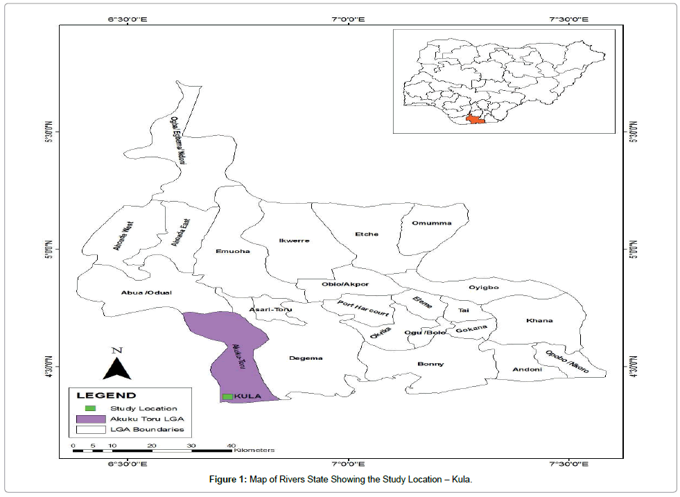
Figure 1: Map of Rivers State Showing the Study Location – Kula.
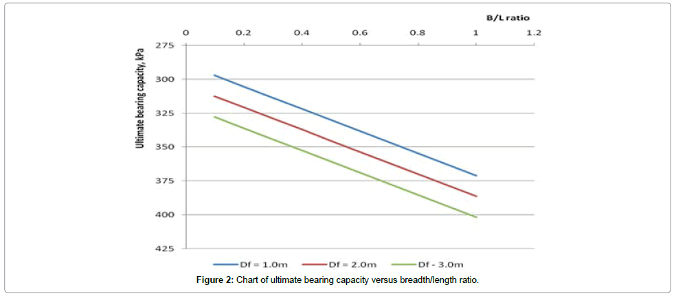
Figure 2: Chart of ultimate bearing capacity versus breadth/length ratio.
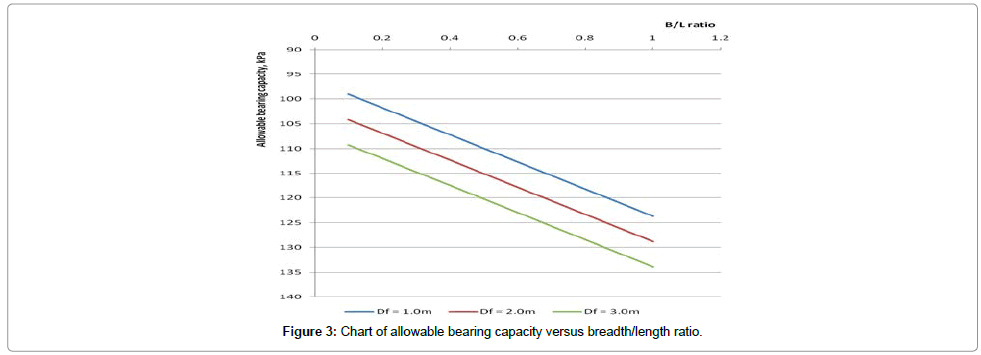
Figure 3: Chart of allowable bearing capacity versus breadth/length ratio.
Sampling/borehole drilling
The investigation comprised mainly exploring nine (9) geotechnical boreholes with soil sampling and measurement of water table and the execution of nine (9) cone penetration testing. The boreholes were drilled by the shell and auger cable percussive drilling method, using a hand rig. The hand rig is fitted with a free fall auger. The auger is lifted to a height of about 1.0 m above ground level, using gloved hands, and allowed to free-fall under gravity to advance the boring. As the auger falls it cuts through the soil such that the cut soil material is retained inside it by means of a clerk (Figures 4 and 5). The auger is then brought to the surface where the soil retained in it is emptied out. To prevent collapse of the borehole wall, the hole is lined with casings or shell corresponding to the size of the auger being used for the drilling. As the drilling continues, the auger drops into the open hole until the time sample is to be taken (Tables 1 and 2).
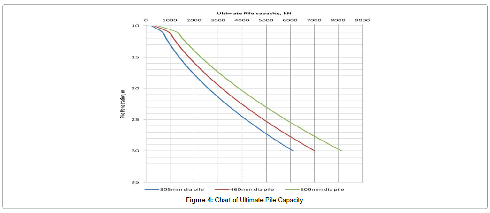
Figure 4: Chart of Ultimate Pile Capacity.
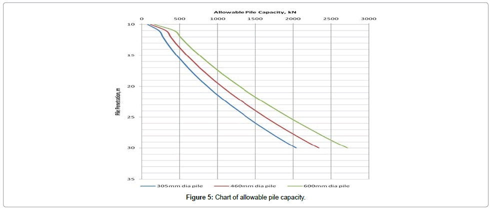
Figure 5: Chart of allowable pile capacity.
| Stratum No. | Description | Average depth range (m) |
|---|---|---|
| 1 | Clay, and sand intercalations, silty, medium mottled brown and grey | 0-2 |
| 2 | Fine sand, silty, loose to dense, grey In borehole 3 (clay to 5.0m) |
2-30 |
Table 1: Soil Stratigraphy to the depth of the borings.
| Min | Max | Mean | |
|---|---|---|---|
| Natural Moisture Content (%) | 18 | 39 | 26 |
| Liquid Limit (%) | 35 | 51 | 43 |
| Plastic Limit (%) | 17 | 33 | 25 |
| Plasticity Index (%) | 13 | 22 | 17 |
| Liquidity Index | 0.06 | 0.71 | 0.32 |
| Consistency Index | 0.94 | 0.29 | 0.68 |
| Bulk Unit Weight(kN/m3) | 18.76 | 18.76 | 18.76 |
| Dry Unit Weight(kN/m3) | 15.34 | 15.34 | 15.34 |
| Final Void Ratio | 0.67 | 0.67 | 0.67 |
| Final Porosity (%) | 47.48 | 47.48 | 47.48 |
| Undrained Strength (kPa) | 48 | 48 | 48 |
| Coefficient of consolidation, m2/yr | 3.66 | 5.12 | 4.22 |
| Coeff. of Compressibility, mv,m2/MN | 0.33 | 0.44 | 0.38 |
Table 2: Range of variations in the Index and Engineering Properties of near surface soils to the Depth of 5.0 m.
Representative undisturbed and disturbed samples were taken at regular intervals of 1.0 m depth, and also when a change in soil type was observed. The samples were used for a detailed and systematic description of the soil in each stratum in terms of its visual and haptic properties and for laboratory analysis. The borehole log obtained is presented in Figure 5. In the cohesive soils, six undisturbed samples were taken for examination and laboratory analysis. The laboratory test results are shown in Tables 3-6, respectively.
| Min | Max | Ave | |
|---|---|---|---|
| Effective Particle Size, d10 (mm) | 0.075 | 0.6 | 0.15 |
| Mean Particle Size, d30(mm) | 0.16 | 0.45 | 0.32 |
| Particle Size, d60 (mm) | 0.16 | 0.45 | 0.32 |
| Coefficient of Uniformity, Cu = d60/ d10 | 2.82 | 9.83 | 4.34 |
| Coefficient of Curvature, Cc = d302/d10.d60 | 0.35 | 1.39 | 1.02 |
Table 3: Range of Variations of the Geotechnical Parameters to a Depth of 25.0 m.
| Foundation depth, Df (m) | Allowable, Qall(kPa) and Safe Bearing Capacity, Qs(kPa), for Various Width, B(m) of Raft Foundation | |||||
|---|---|---|---|---|---|---|
| 2m | 5m | 10m | ||||
| Qall | Qs | Qall | Qs | Qall | Qs | |
| 1 | 98 | 60 | 102 | 52 | 110 | 35 |
| 2 | 104 | 95 | 107 | 75 | 115 | 55 |
| 3 | 109 | 105 | 113 | 110 | 120 | 75 |
Table 4: Allowable and safe bearing capacities for various foundation widths at different foundation depths.
| BH No | Depth, m | Angle of internal friction, φ | Pile-wall friction, δ |
|---|---|---|---|
| 1 | 5 | 34 | 26 |
| 17 | 40 | 30 | |
| 2 | 8 | 38 | 29 |
| 27 | 32 | 24 | |
| 3 | 8 | 41 | 31 |
| 28 | 35 | 26 |
Table 5: Design parameters for cohesionless soil, using the angle of internal friction as obtained from the laboratory shear box test.
| Pile depth (m) | Allowable Pile Capacity, kPa, for Various Pile diameter | ||
|---|---|---|---|
| 305mm (12”) Pile | 460mm (18”) Pile | 600mm (24”) Pile | |
| 10 | 93 | 140 | 198 |
| 15 | 553 | 713 | 914 |
| 20 | 1036 | 1263 | 1547 |
| 25 | 1668 | 1961 | 2329 |
| 30 | 2448 | 2808 | 3259 |
Table 6: Allowable bearing capacity and specific pile diameter for specific depths.
Standard Penetration Tests (SPT) was carried out at regular intervals of depth in the granular sediments in order to assess the in situ densities. In this test, the number of blows required to drive the standard sampling spoon 300 m penetration after the initial sitting drive was recorded as the SPT (N) value. Six (6) numbers Cone Penetration tests were carried out to refusal. Readings of cone tip resistance and sleeve friction were taken at every 0.2 m interval of depth. A CPT rig and cones were used for the tests. Field measurements ground water showed that the ground water levels stood at between 2.50 and 3.0 m below the existing ground surface in all boreholes explored at the time of the field work.
Laboratory tests
Detailed laboratory investigations were carried out on representative undisturbed and disturbed samples obtained from the boreholes for the classification tests and other tests. All tests were carried out in accordance with BS 1377 (1990). Atterberg consistency limit tests were carried out on the cohesive samples. The results show that the samples are low to medium plasticity silty clay. The particle size distributions of a number of representative samples of the cohesionless soils were determined by sieve analysis. The results disclosed that the samples are predominantly, fine, fine to medium and medium sands.
Unconsolidated Undrained triaxial (UU) tests were performed on relatively undisturbed samples obtained from the boreholes. Test results show the average unconsolidated undrained shear strength parameters for the clays encountered in the study area. Laboratory consolidated tests were carried out on relatively undisturbed samples with the objectives of determining the compressibility properties of the soils. The plot of void ratio (e) against effective pressure (P) for the samples tested and calculated values of the coefficients of consolidation (Cv) and of the coefficients of compressibility (Mv).
Test results showed that the samples were of moderately high compressibility and predominantly exhibiting negligible swelling potentials (Table 2).
Soil stratigraphy
The soil stratigraphy encountered on the study site as obtained from the explored boreholes are as presented in Table 1. The lithology revealed intercalations of clay and sand in thin layers to a depth of 2.0 m below the existing ground level as presented in boreholes 1 and 2. Below this depth, the formation presents a stratum of medium dense fine sand that increases in gradation and density with depth to becoming dense fine to medium sand at about 7.0 m below ground level. Borehole 3, however, revealed a 5.0 m thick near surface clay layer overlying the medium dense fine sand. The sand increases in density to become very dense at about 10 m. Below this depth, at about 25.0 m below the existing ground level medium dense sand is encountered again. This medium dense layer is observed to the final depth of the boring.
Engineering soil properties
The near surface soil encountered during the investigation is firm clay extending from the ground level to a depth of 2.0 below the ground surface and extending to 5.0 m in Borehole 3. This firm clay is characterized by moderate compressibility, low moisture content and low undrained strength. The range of variations in the index and engineering parameters of this near surface soil are shown in Table 2.
Loose to medium dense sand was encountered immediately beneath the near surface silty clay soil. This loose to medium dense sand increases in density to becoming dense to very dense sand from about 7.0 m below the existing ground level. Deeper down in the boring from about 25.0 m, it is observed that the sand loosens to becoming medium dense. This medium dense sand continues to the final depth of the investigation. The ranges of variations of the geotechnical parameters are shown in Table 3.
Soil foundation design parameters
The study has revealed the relevant soil parameters for the design of the foundation of the cellar slab. The near surface soil is 2.0 m thick intercalations of clay and sand in Boreholes 1 and 2 and a 5.0 m thick clay layer in Borehole 3. Underlying this near surface clay is a formation of loose sand becoming medium dense and dense sand with depth.
The lithology revealed a stratum of graded bed. The upper sand stratum being loose and fine sand immediately beneath the clay layer and grading to become medium dense sand with depth. This gradation continues as the borehole advances and deeper down some loosening of the sand is observed. This loosening is observed to the final depth of the borehole. From consideration of the nature of the intended structure, the anticipated load, the moderate compressibility of the near surface clay and the underlying loose silty sand, it is suggested that the cellar slab be supported on raft foundations founded in the upper clay. However, where the requirements preclude the use of raft foundation, pile foundation should be employed to transmit the load to the underlying soil stratum. Using a safety factor of 3 on the ultimate bearing capacity, the chart for the allowable bearing capacity is as presented in Figure 2 while also using a safety factor of 3 on the ultimate pile capacity, the chart for the allowable pile capacity is as presented in Figure 5.
Bearing capacity calculations
The bearing capacity for the foundation was determined using the Terzaghi [7] bearing capacity formulae as stated below:
 (1)
(1)
where qd = Ultimate bearing capacity
c = Undrained cohesion of the soil
B = Width of footing
L = Length of footing
γ = Unit weight of soil
Df = Depth of footing
Φ = Angle of friction taking as zero for undrained condition of the soil.
Settlement calculations
The settlement for the footing is determined using the Terzaghi [7], Skempton and MacDonald [8] formulae and the Bousinesq’s chart.
St = Si + Sc (2)
where St = total settlement
Si = immediate settlement for
Sc = consolidation settlement at depth of footing
Calculation of immediate settlement, Si
St = qB(1-μ2) Ip/E (3)
Q = imposed load
B = footing width, m
Μ = Poisson’s ratio for undrained shear strength
Ip = Influence factor for a rectangular footing
E = Stiffness modulus for the firm sandy clay
Calculation of consolidation settlement, Sc
Sc = 0.7 × Soed (4)
Soed = mv × σ × H
mv = coefficient of volume compressibility
σ = Applied pressure at point under consideration = qxIf
H = Thickness of strata under consideration = 2B
If = Influence factor from Bousinesq’s chart
0.7= geological coefficient that relates oedometer results to actual field estimates
Calculation of total settlement, St
St = Si + Sc (5)
Safe bearing capacity, Qs
Table 4 shows the allowable, Qall (kPa) and safe Qs (kPa) bearing capacities for various foundation width, B(m) of raft footing at different foundation depth, Df, m. The safe bearing capacity for the raft foundation is limited by a maximum settlement value of 50 mm.
Bearing capacity calculations – pile foundation
The ultimate bearing capacity, Qu, of driven piles is determined by the equation below:
Qu = Qp + Qf (6)
where Qp = q x Ap = total end bearing, kN
Qf = f x As = skin friction resistance, kN
And, q = unit end bearing capacity = kPa
f = unit skin friction = kPa
Ap = gross end area of pile, m2
As = side surface area of pile, m2
End bearing and skin friction in cohesive soils
For piles in cohesive soils,
The unit skin friction, f = α.Su (7)
The unit end bearing, q = 9. Su (8)
Where α = 0.5ψ-0.50 for ψ < 1.0
α = 0.5ψ-0.25 for ψ > 1.0
and α = Su/Po
Su = undrained shear strength of the soil at the point, kPa
Po = effective overburden pressure of the soil at the point, kPa
End bearing and skin friction in cohesionless soils
For piles in cohesionless soils,
The unit skin friction, f = K Po tanδ (9)
The unit end bearing, q = Po Nq (10)
Where
K = coefficient of lateral earth pressure
δ = friction angle between the soil and pile wall
Nq = bearing capacity factor
This study has revealed a near surface stratigraphy of silty clay to a depth of 5 m underlain by loose silty sand to a depth of 9.0 m below the existing ground level. Underlying this layer of loose sand is a 1.0 m thick layer of plastic clay. Considering the nature of the intended structure, the anticipated load and the moderate compressibility of the near surface silty clay and the underlying loose silty sand, it is suggested that the cellar slab be supported by means of raft foundation founded within the upper clay layer where it is uneconomical to take it deeper. The plastic clay beneath the cellar slab, however, will undergo consolidation along with the compression and creep that will result from loading the loose sand beneath it. Adequate consideration should be taken of this settlement during the design and construction of the cellar slab.