International Journal of Advancements in Technology
Open Access
ISSN: 0976-4860
ISSN: 0976-4860
Research Article - (2018) Volume 9, Issue 2
More recently, several studies have been done to improve the mechanical properties of materials. During this period, various methods of SPD (severe plastic deformation (SPD)) have been used to produce Ultra-Fine-Grain (UFG) materials. One of the pioneers in replacing SPD is the elliptical cross-sectional flattened extrusion (ECSEE). In the present study, an optimal combination of the process parameters of the ECSEE method, such as the torsional angle, ellipticity and elliptical diameter ratio, to obtain the maximum effective pressure and minimum punch force, as well as the minimum subsequent error in the cross section of the ABAQUS Software for modeling Numeric done. Due to the design of the central composite test, models of punch force response levels, effective pressure and subsequent error are generated through FE simulation. The simulation results showed that the effective strain was significantly affected by the rotation angle, diameter ratio and channel length. After two ECSEE courses, power ranged from 384 MPa to 340 MPa and its life span was reduced from 15% to 8%. Also, the FEM results indicate that the amount of effective pressure on the surface is greater than the center of the ECSEE pen. The results showed that the torsional angle of 120°, the length of the diameter of 16 and the ratio of the axis to 1.45, the optimal solution give the desired quality characteristics.
Keywords: Finite element modelling; Severe plastic deformation; Response surface methodology; Elliptical cross-sectional flattened extrusion; Mechanical property
Over the last few years, the demand for extra virgin maize (UFG) materials and structural materials of the nanotube has increased. In order to achieve this goal, intensive plastic deformation (SPD) techniques have been used, which include high-intensity deformation processes that improve the mechanical properties of materials. Various SPD methods, such as ECAP, HPT, CGP, CEC, TE, and ARB, are available to access Nano structural materials that are dependent on the process, shape, and so on. The SPD method can be used on both the laboratory and industrial scale.
By various researchers to produce ultra-heavy metals (UFG) or nanostructures. Applying a high-pressure deformation switch through a special material will improve grain refinement, unique properties and mechanical properties. Over the past decades, SPD processes have been widely used in various fields, in particular at pressing the same channel angle (ECAP) [1], high pressure indentation (HPT) [2], limited pressure (CGP) [3,4], bending extrusion (TE) [5,6], roll expansion (ARB) [7] and limitations, etc. SPD technology is an emerging process in applications not only in laboratory scale, But also in the industries for business development [8].
One of the broadest widely used methods, twisted extrusion can produce tremendous grain materials. However, the TE greater limitation is only for rectangular pieces, while the raw material has a cylindrical portion.
To counter this task by Wang et al. A new SPD technique called Equivalent Extrusion Equivalent Elliptical Channel (ECSEE) [9] has been introduced. Torsion, extrusion and insufficiency are used in this process. In this process, there are three main stages: round to elliptical (L1), oval to ellipse (L2) and oval to far (L3), which should be extruded step by step (Figure 1). Since the mold has a spiral, the work piece collides with the upper strain while the section does not change.

Figure 1: A schematic illustration of elliptical cross sectioned equal channel extrusion process.
Although there are numerous effects on the production of UFG materials using SPD technology, there is no comprehensive study to improve the ECSEE material status. The acquisition of superb grain materials using Elliptical cross-sectional flattened extrusion (ECSEE) [9]. They used a 3D elemental element model to study the behavior of materials during the process. To confirm FE results, they use a set of experimental experiments. Their achievements indicate that the amount of pressure at the edges above the centres.
The use of ECSEE and strain distribution analysis in deformed plastic is deformed [10]. The DEFORM software was used to create three-dimensional lens simulation and to determine the plastic pressure variations in the work piece. The results showed that the remote sensing region is more than the central samples.
In another effort, Wang et al. [11] developed a simple analytic model based on slice-plain-Strain simple method and developed an incremental evolutionary theory to predict the efficient simulation of the ECSEE process. According to them, the mechanism of deformation in the ECSEE can be divided into two stages: first, the deformation of the oval / elliptic circular cross-sectional channel, and the second, the deformation of the tidal transition channel of the elliptical crosssection, through the tracing of a particle of Cross section. Rules for the effective accumulation of particle particles with channel length were changed and an effective mix distribution (ES) was obtained through MATLAB, then a FEM decomposition analysis using Deform-3D was performed. As a result, shear deformation prevails and the tensile stress of ECSEE accumulation is more than other forms. An empty section of the ES indicates the gradient of the edge-to-center disappearance. The FEM results also prove the accuracy of the analytic solution. In order to obtain the optimal geometry, the maximum shear stress coefficient and maximum correlation coefficient, as well as the higher damage coefficient, Wang et al. [12] combine the simulation of finite element with gray decision theory. ECSEE optimized a combination of process parameters: torsional angle 120°, axle ratio 1.55 and first length 7 mm, second length 10 mm and third length 10 mm. Experimental and simulation results show that the material can be corrected with structural parameters optimized from the mold.
Therefore, optimization results are satisfactory. Lee et al. [13] simulated and experimented experiments at the ECSEE with high purity aluminum to study the normal and biomechanical distributions of the disruption equation on the three right planes as well as changes in the microstructure characteristics of the materials. The simulation result shows a significant slope in three levels as well as the evolution of the microstructure. The simulation result shows a significant slope in three levels. The results of microarray experiments show that the slope is the same as strain distribution. According to the results of the Transmission Electron Microscopy (TEM), the microstructure evolution from a grainy structure to a superb structure has affected the shear, substrate, grain boundaries and equaiaxed structures [14].
Solving Such Problems Optimizing Multiple Responses Using this method, combining multiple responses into a meaningless performance measure yields a desirable performance [15]. Various studies have been done to optimize the production process by using statistical methods in machining [16,17], welding [18,19], metal forming [20,21], coating [22,23], etc. Therefore, the method Applicability of this problem can be used in modeling and optimization of pipe design process. Many researches have used RSM to optimize various processes, such as the tube elongation process used to produce square tubes [24]. They optimized the process parameters of the pipe, such as input speed, bearing length, friction coefficient and particle angle, using simulation simulation FE and empirical test. The composite matrix design was used to obtain optimal parameters. Optimize traction performance on FSW from AA5052 to AISI 304 different connections by HD. NN (neural network) and GA (genetic algorithm) have been used to achieve tensile properties [25]. The design matrix includes 27 experimental experiments with regard to the change in tool rotation speed, tool weld and offset. DOE (experimental design), RSM, and Colony algorithm for honey bee to optimize rectangular tube parameters are used [26]. They examined the effects of geometric error parameters, thickness distribution and tensile strength. Meyras Aban Jafari et al. [27] optimized the spring return phenomenon in the deep drawing process using ANFIS to achieve the minimum spring return. The parameters studied in this study were temperature, low punch radius, death restoration, peak height.
Based on the literature, it has been shown that AL7075 aluminum processing has not been reported with the use of ECSEE to produce UFG materials. But the ECSEE process involves many parameters and complex interactions between them. An approach to a factor at a time requires more testing to systematically identify the effects of process parameters. Therefore, the statistical design of the experiments has shown that efficient approaches for systematically examining the parameters of the interconnection process are presented. In addition, the optimization of the ECSEE process involves numerous factors and multiple responses to AL7075 in the literature. Hence, in this paper, the empirical relationships between the important input variables, the rotation angle, the ellipticity length, and the ratio of the oval diameter to the punch force, the effective pressure and the lateral error in the cross section using RSM are investigated. In addition, this paper shows how a number of overlapping response levels can be used to select the operations needed to achieve the desired specifications and optimize ECSEE. It should be noted that the selected range for parameters and conclusions specifically relates to the microstructure and analysis of the mechanical properties of the highly plastic parts. According to literary studies, there is no available research to enhance the spatial property of the AL7075 using the ECSEE method. Most of the earlier research was about the study of mechanical properties, but in this research we have tried to optimize the process parameters to obtain the desired result and properties along with the mechanical properties of the AL7075.
The materials used in this experiment are aluminum 7075 with a diameter of 9 mm and a length of 110 mm, which is the most used in the industry. A specially designed stainless steel AISI H13 steel plate is made using a CNC lathe and is hardened to heat the hardness and abrasion resistance. A universal machine with a maximum capacity of 100 tons has been used to transfer the AL7075 rods through the mentioned particle. The experiments were carried out at the extrusion speed of 5 mm / min at room temperature and lubricated vegetable oils. Figures 2a-2e shows the experimental settings, including the mold, the press machine, and the work before and after the deformation.

Figure 2a: Assembled die.

Figure 2b: Work piece before and after process.

Figure 2c: Used punch.

Figure 2d: Schematic view of video measuring machine.

Figure 2e: Difference between ECSEEd billet and ideal die.
The press machine was equipped with a digital barcode that can be applied to the applied force and relative displacement during the process. Therefore, the machine is able to measure the maximum punch force for each test.
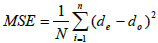
In this study, an image measuring device (VMM) with a resolution of 1 μm was used to measure ECSEEd characteristics and its dimensional accuracy using the Mean Square Error Method (MSE) based on the following equation.
 (1a)
(1a)
Where MSE is the mean square error, N is the number of points (measurements) around the ECSEEd section, the expected dimensions, and whether dimensions are obtained. Figure 2d shows an overview of this issue.
To measure the geometric accuracy of FEM, the difference between the geometric shape of the idea and the ECSEE schematic geometry was measured at 28 points, and then the MSE was calculated. When the ABAQUS-limited element modeling was performed, the coordinates of the BILET sector were extracted and then entered CATIA to create a 2D model using the SPILNE curve.
A set of process force measurement was created at ABAQUS and awarded to a punch, and then the maximum force recorded in comparison with the test results was recorded. The press used represents the maximum force per bar. The maximum number of reads is converted to Newton units. Using equation 1-b, the maximum force is calculated.
F=P.A (1b)
Where, F is the compressive force, the effective P pressure that can be pumped from the pressure cell and A is an effective piston zone.
Finite element simulation
To find out the behavior of material deformation by the ECSEE, simulation of the limited element of the process was performed by ABAQUS explicit software. The standard tensile test was performed and mechanical properties such as tensile strength and Poisson ratio with density were entered in the property modulus. Characteristics of Al 7075 materials are shown in Table 1 and Figure 3.
| Property | ν | ρ(kg/m3) | E(GPa) |
|---|---|---|---|
| Value | 0/3 | 2800 | 71/7 |
Table 1: Material property of Al7075.

Figure 3: True stress-strain of AL7075.
The R3d4 elements were used for die modeling, which was used as a rigid object, and Bildt using C3D8R as an unstable component. Figure 4 elucidates 3D models of the process.

Figure 4: 3D FEM model of ECSSE process.
Low Coulomb friction is used to model friction between parts and has a coefficient of 0.2. Also, in this research, the contact level surface model was used.
Validation of FEM results
The FEM results are confirmed by experimental results, and the achievements are shown in Table 2. According to the table, it is concluded that there is a good agreement between the FE simulation results with those who have been tested. In order to verify the simulation results of FE, an approved test was performed and two criteria including punch force with dimensional accuracy for verification were discussed and discussed further in the discussion section.
| Pass no | Criterion | Simulation | Experiment | Error (%) |
|---|---|---|---|---|
| First pass | Force | 99(KN) | 106 | 6 |
| Dimensional error | 0.378 | 0.399 | 5 | |
| Second pass | Force | 119(KN) | 129 | 7 |
| Dimensional error | 0.324 | 0.365 | 4 |
Table 2: Verification result.
Construction of design matrix
One of the main objectives of this study was modeling the ECSEE process to predict the characteristics. According to the results, the FE model can be used for this purpose. However, this will be a time consuming process, because each model FE model may take a few hours. Therefore, as an efficient predictive method, RSM was used here to communicate the relationship between ECSEEs and process responses (i.e., punch force, mean square error, and effective error) for each set of process parameters. A collection of simulations was carried out based on the experimental design methodology (DOE) to collect the required information.
The torsional angle, the axial of the oval and the length of the channel were considered as input parameters. The ranges of these parameters and their levels (three levels for each parameter) are presented in Table 3. To design a complete factorial, the number of possible designs (N) N=Lm, in which L is the number of levels for each factor and m is the number of factors. Therefore, the complete factors for input parameters in this study will be 27 tests. In order to further reduce the number of simulations, four factors and three levels of Box-Box design are implemented. Using this approach, only 13 runs are required to generate the data needed to develop RSM models. Table 4 shows the main design matrix and the value of the response.
| Factors | Symbol | Unit | Level 1 | Level 2 | Level 3 |
|---|---|---|---|---|---|
| Torsion angle | Φ | deg | 60 | 90 | 120 |
| Channel length | L | mm | 10 | 13 | 16 |
| Axis ratio | m | - | 1.25 | 1.35 | 1.45 |
Table 3: Process factors and their levels.
| No | Φ | L2 | m | Force | Strain | Dimensional error |
|---|---|---|---|---|---|---|
| 1 | 60 | 10 | 1.35 | 92174.1 | 0.38765 | 0.440886 |
| 2 | 120 | 10 | 1.35 | 99725.5 | 0.37864 | 0.454987 |
| 3 | 60 | 16 | 1.35 | 124142 | 0.3209 | 0.46764 |
| 4 | 120 | 16 | 1.35 | 23716.4 | 0.426 | 0.34 |
| 5 | 60 | 13 | 1.25 | 34427.4 | 0.423 | 0.422971 |
| 6 | 120 | 13 | 1.25 | 111424 | 0.36874 | 0.477759 |
| 7 | 60 | 13 | 1.45 | 37046.4 | 0.4123 | 0.331867 |
| 8 | 120 | 13 | 1.45 | 138518 | 0.2102 | 0.698 |
| 9 | 90 | 10 | 1.25 | 11476 | 0.467 | 0.344993 |
| 10 | 90 | 16 | 1.25 | 43189.7 | 0.4001 | 0.316009 |
| 11 | 90 | 10 | 1.45 | 149491.1 | 0.201 | 0.4010 |
| 12 | 90 | 16 | 1.45 | 131335 | 0.276 | 0.808 |
| 13 | 90 | 13 | 1.35 | 138976 | 0.213 | 0.442405 |
Table 4: Design matrix and calculated values of responses.
Mathematical model of responses
RSM is a method for determining the relationship between different process parameters with different ECSEE criteria and examining the effect of these process parameters on the relationship [14], i.e., punch force, effective pressure and mean square error. In order to investigate the effect of ESCEE parameters on the above responses, the mathematical model of the second-order polynomial response level can be as follows for evaluating the parametric effects on process characteristics.
Where y is the responses (i.e., punch force, effective pressure and mean squared error); b0, bi, bii and bij are coefficients; Xiu is the variable (Φ, L, and m); you have the number of tests (1-13). k is the number (1-3); Xiu2 is the term above the variable and Xiu, Xju are interacting.
Based on equation (1-b), the effects of the process variables mentioned above are found on the punch force, the mean squared square and the effective elasticity by calculating the various constants of the equation (2) using the V8 design expert and using the data in Table 3. Mathematical relations are presented for correlating the answers mentioned in equations 2, 3 and 4.
Force=-7.31328E+006+7257.92361* fi+1.54797E+005*
L+8.73450E+006 * M-31.97528 * fi2-2806.52778 * L2-2.98443E+006 * M2-299.93611 * fi * L+2039.58* fi M-41558.16667 * L * M
Strain=17.132-0.030489*fi-0.42611 L-19.96381* M+1.03456E-005 fi2. 648639E-004 * L2+5.09332 * M2-3.93725E-004 * fi * L+0.025945 * fi * M+0.36332 * L * M (3)
MSE=+13.33889-6.43968E-003* fi-0.40207 * L-14.39644 * M+1.01574E-004 * fi2+8.20903E-003 * L2+4.91437 * M2+3.16972E-004 * fi * L-0.012320 * fi * M+0.11825 * L * M (4)
Figure 5 shows the effect of factor factors on response in terms of interactions. As can be seen from the figure, process factors have a different effect on responses. For example, the effect of the angle of rotation on the response is different. For this purpose, optimization should be done to determine the optimal parameter for optimal performance.

Figure 5: 3D surfaces showing interaction effect of process factors on (a) Punch force (b) Effective strain and (c) Dimensional change.
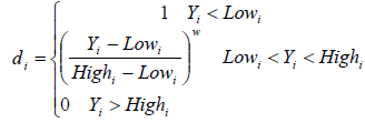
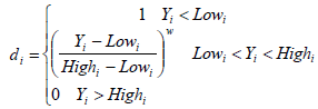
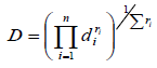
In the present work, the individual utility of each response, di, was calculated using equations (5) - (7). The shape of the utility function can be changed for any target of wi weight. More weight is emphasized on higher and lower levels. The weight can range from 0.1 to 10; weight has more than 1 emphasis on the target, while weighing less than 1 emphasis. When the weight is equal to 1, this will cause the difference from 0 to 1 in linear mode. The optimal target function (D), the importance of each response (r) in Equation (5) is shown.
Where n is the number of responses in the measure and ri is the target value of ith response.
For goal of maximum, the desirability is defined by:
 (5)
(5)
For goal of minimum, the desirability is defined by:
 (6)
(6)
 (7)
(7)
With this technique, optimal performance can be found as a point or more for numerical optimization of the process.
The utility functions satisfy all the responses with the required upper or lower required requirements and searches for the optimal test conditions for the ECSEE function. The ultimate goal is to produce the minimum punch force and the average square error as well as the maximum stress equivalent. In the present study, optimization was done using a design specialist. Table 5 provides a suitable benchmark for optimization. Table 6 also provides optimal operating conditions.
| Factor/Response | Units | Goal | Lower limit | Upper limit | Importance |
|---|---|---|---|---|---|
| Torsion angle | deg | Is in range | 60 | 90 | 3 |
| Channel length | mm | Is in range | 10 | 16 | 3 |
| Axis ratio | - | Is in range | 1.25 | 1.45 | 3 |
| Punch force | N | Is minimum | 5 | 149491 | 11476 |
| Mean square error | - | Is minimum | 2 | 0.467 | 0.201 |
| Strain | - | Is maximum | 5 | 0.608 | 0.116009 |
Table 5: Appropriate criterion for optimization.
| Process factors | Responses | |||||
|---|---|---|---|---|---|---|
| α (deg) | L (mm) | m | Punch force (N) | Mean square error | Strain | Desirability (%) |
| 120 | 16 | 1.45 | 60629.8 | 0.3631 | 0.587 | 73.8 |
Table 6: Most desirable factor combination which was obtained through desirability function.
From Table 6, it can be seen that the most favourable operating conditions, the torsional angle is 120 degrees, the length of the deformation is 16 mm and the axis ratio is 1.45. These optimal operating conditions, with 73.8% of the optimum value, can produce optimal production due to low punch force and average square error as well as high reverse stresses.
In order to validate the optimal process parameters obtained through a desirable approach, an additional FEM test and confirmation with optimal conditions were obtained. The results are listed in Table 7. This proves that the characteristics of the optimal quality of a billet can be obtained using the optimal process parameters. In addition, the measured results are in good agreement with predicted results and their error rates range from 5 to 8.5%.
| ECSEE performance | Units | Desirability function | FEM simulation | Experiment |
|---|---|---|---|---|
| Punch force | N | 60629.8 | 61459.4 | 58975.1 |
| Strain | 0.58744 | 0.576 | 0.56342 | |
| Mean square error | - | 0.3631 | 0.358 | 0.337 |
Table 7: Result of confirmatory experiment according to optimal factor combination.
In order to demonstrate the efficiency of the proposed method, an experimental test was performed by adjusting the optimal parameter and the strain distribution, hardness profile and micro hardness were investigated and compared with the values of parent material. As shown in Figure 6, the value of the strain is equivalent to the cross-section in the radial direction from the margin to the center of the rod. However, in the center of the section, the tensions of the equivalent increase to some extent.

Figure 6: Strain distribution of deformed part.
Due to this distribution, it is expected that the microstructure of the materials in these areas will be weaker and so hardness will increase. Figure 7 shows the microstructure of the deformed part after ECSEE. As seen in the figure, areas that are subject to severe plastic changes are much more subtle than finely ground metals.

Figure 7: Microstructure of (a) Base metal (b) Deformed rods after ECSEE.
In addition, the ECSEE process was performed for the second time on a sample, as shown below in Figure 8, it has been shown that grain distribution becomes more precise, which increases the tensile strength and reduces the plasticity by more than 10% 50 microns.

Figure 8: (a) Microstructure after the first time (b) Microstructure after passing second (c) Tensile strength vs. pass number (d) Length vs. pass number.
In addition, the tensile strength variations are shown in Figure 9. For better analysis, the charts are divided into several regions. In the A zone, the billet is entered to the die but it hasn’t reached the deformation zone. In area B, the billet is introduced into the deformed region, which has 3 ellipticity; this region has the highest amount of force due to compressive stress. In area C, the ingots are removed from the mold. This is the main reason for the downtrend.

Figure 9: Force variation during the process in detail.
In the present study, a hybrid study based on the simulation of FE and RSM was performed to determine the optimal parameter of the ECSEE process. Experimental experiments with one and two ECSEE passes were performed in optimal parameter setting and microstructure and mechanical properties were analysed. The results can be summarized as follows:
• The FE model has been compared with experimental observations and good agreement with error values of less than 10% according to punch force and dimensional accuracy.
• A limited element analysis of the ECSEE process shows that the amount of effective strain of billet from the surface to the ECSEEd center is reduced.
• It is found that for all responses, the second-order regression equation, which consists of two factors of interaction, is the sufficiency of correlation between input and output.
• Optimization using the utility function has been specified that setting the torsion angle of 120 degrees, 16-inch length and the ratio of the axis of 1.45 is the best solution, which leads to the desired qualities of the quality.
• It was found that the value of the strain equivalent to the cross section in the radial direction from the boundary of the rod to its center was reduced, and a similar trend was observed in the distribution of microorganisms due to the change in the microstructure.
• It has been seen that increasing the number of ECSEE tracks increases tensile strength and decreases life expectancy, which is due to the distribution of sharp grains.
• The strength reached 387 Mpa from 340 Mpa and the elongation dwindled to 8% from 15%.
Based on the results, the ECSEE developed in this article can be used in industrial applications.