Journal of Biomedical Engineering and Medical Devices
Open Access
ISSN: 2475-7586
ISSN: 2475-7586
Research Article - (2019)Volume 4, Issue 2
In the present work, a finite element-based study is undertaken to evolve a design methodology for developing a polymeric stent. Design steps include (1) crimping a stent cut from a polymer tube having outer diameter of 3 mm to a crimped diameter of 1.6 mm, (2) crimping recoil, (3) deployment of crimped stent to 3.3 mm outer diameter, (4) expansion recoil (mimicking crimping and dilation process to treat a 3 mm inner diameter artery) and (5) recoil under pressure. Effect of stent geometry parameters such as crown radius, length, width and thickness on the performance parameters such as radial strength, parallel plate collapse force, radial stiffness, recoil, foreshortening, maximum stresses, and strains are studied. The parametric study further aims to develop a design methodology for polymeric stent mechanical performance evaluation. The effect of crown shape and connector design on stent performance is discussed. Stent design parameters and material property optimization are reported for a polymeric stent.
Finite element method; Polymeric stent; Radial strength; Flexibility; Collapse pressure; Balloon expansion
Cardiovascular Diseases (CVDs) cause a higher number of deaths globally than due to any other disease, corresponding to high social and economic costs. Over three-quarters of CVD, deaths take place in low and middle-income countries [1,2].
CVD covers a wide range of diseases affecting the heart and the blood vessels, including coronary artery disease (CAD), cerebrovascular disease, congenital heart disease, heart attack, heart failure, high blood pressure, and stroke. CAD is often related to atherosclerosis, degeneration of the vessel wall causing several events, ranging from arterial hardening to lumen narrowing (stenosis) potentially resulting in a heart attack or stroke. CAD’s refers explicitly to the arteries of the heart, which carries blood and oxygen to the heart muscles. Depending on the severity of the situation, the CAD is treated using medical treatment (restriction on diet and consumption of pharmacological agents), surgical treatment (coronary artery bypass grafting (CABG)) or interventional cardiology (Percutaneous transluminal coronary angioplasty- PTCA), laser revascularization technique and stenting. The purpose of such procedures is to restore the blood flow to the heart. In the stenting procedure, tubular metallic/polymer mesh called ‘stent’ is placed to keep open the artery. The stent is left there to provide the radial support during the remodeling process of the lumen and can be resorbed in the body after a few months in case of a biodegradable polymer stent.
The stent design cycle can be divided into three groups:
• Manufacturing (crimping)
• Delivery (flexibility) and
• Deployment (Short and long term).
The present study considers only the manufacturing, delivery, and short-term deployment phase of a polymeric stent design typically called as bioresorbable vascular stent or BVS. The overall mechanical response of a stent can be suitably designed by changing the geometrical arrangement and unit cell parameters. Post-stenting complications such as stent thrombosis, restenosis, and inflammation have been related to stent design and material in the past [3-6]. Radial strength and stiffness are found to be the most important parameters for a stent crown design [7]. An ideal stent design demands optimization to many contradicting requirements [8]. A lower radial force is desired during crimping and deployment while a higher radial force is required after deployment. Another critical design feature is the connector design which provides flexibility to the stent as it has to pass through a tortuous path of arteries for deployment. Finite element simulations are very useful and recommended by various standards (ASTM 2514-08) as a design tool for stent design and validation studies.
Various guidelines are available for metal-based stent design (stainless steel, cobalt-chromium) and are used to design a polymeric stent. In metallic stent design, the strength is attributed to yielding (yield strength), and ultimate tensile strength is an essential criterion of failure [9]. However, the bioresorbable polymers such as PLLA (poly(L-lactic acid)) are brittle, and elongation at break is very low (<5%) compared to metals (20-40%) therefore, increasing the toughness of polymeric material by some blending and minimizing the yielding and strain of struts should become the primary design objective for polymeric stents [10,11]. A viscoelastic material model can give a clearer picture during crimping and longterm performance such as recoil due to creep and degradation [12]. Fatigue modeling of the bioresorbable polymer stent is challenging due to the deterioration of struts by degradation and unavailability of stress-cycle (S-N) curve data for pure polymer, eg. PLLA or its blends and copolymers.
Also, the guidelines for the selection of a stent to be adapted to an intended application site (artery diameter) are not very clear in the existing literature. A polymer stent is cut on 3 mm outer diameter polymer tube to treat a 3 mm inner diameter plaque artery. The stent undergoes plastic deformation at crowns during crimping and loses some strength. It is then over expanded (3.2-3.5 mm) during dilation and is expected to support the lumen due to its elasticity. It is also the aim of this study to find the effect of various starting diameters on stress and strain during a cycle of complete loading, including crimping and deployment, to discuss this dialogue further.
The mechanism to describe the effect of temperature (Tg-the glass transition temperature) of a polymer during crimping is discussed in a few studies [13]. A few simulation studies incorporate this by using the lower Young’s modulus and lower yield strength of PLLA at 45°C (glass transition temperature). The effect of temperature on recoil and radial force is also studied. Only a few studies report the radial force values of a polymeric stent, which is the main focus of this study as well [14].
Although the superiority of a polymer stent over the drug-eluting metal-based stent is still not established. A bioresorbable polymer stent is a way to future as,
• It can provide mechanical support to prevent recoil and restenosis.
• Compatibility with noninvasive imaging technologies such as magnetic resonance imaging (MRI).
• Future surgical revascularization possible and
• Positive remodeling and physiological response to pulsatile blood flow.
BVS will fade away or resorbed in the body after doing its work of drug elution and benefiting the arterial remodeling [15,16].
A stent design consists of designing mainly two components, the wavy circumferential ring or crowns which provide the radial strength to support the lumen and the connectors which provide the flexibility during deployment as shown in Stent design features (Figure 1).

Figure 1: Stent design features (polymer).
The stent can also be thought of as a number of springs connected in series. Unit ring or hoops provide the radial stiffness and connectors provide the axial and bending stiffness to the stent. A basic design of the crown is chosen here where sinusoidal hoops are connected by three straight connectors, and this is repeated along the central axis to form the stent of the desired length.
Unit ring parametric study
Various parameters of a unit crown are shown in parametric unit ring (Figure 2 (a)). A parametric model is made in computer-aided design (CAD) software (Solid Works) and imported for computeraided engineering (CAE) simulations (ABAQUS Explicit). Following steps are simulated.
Step 1: Stent crimping from an outer diameter of 3.0 mm to 1.6 mm (Dcrimp) (crimping)
Step 2: Unloading or crimping recoil (elastic recovery)
Step 3: Stent expansion to 3.3 mm outer diameter (Dexp) (dilation).
Step 4: Unloading or expansion recoil (elastic recoil)
Step 5: Application of 2 bar pressure (Immediate elastic recoil force from the artery and plaque)
Stent outer diameter after crimping recoil (Step-2) and expansion recoil (Step-4), Dcrimp_recoil and Dexp_recoil was measured.
Two model cylinders were given inside and outside radial displacement with frictionless tangential and hard normal contact between the cylinder and the stent. Self-contact for the stent was also created. Three points on the outer surface of the unit ring were constrained to not move in the axial direction. An elastic-plastic polymer (PLLA) material property (Young's modulus E=3.4 GPa, Poisson ratio μ=0.33 and yield strength σy=60 MPa) is used. A finite element mesh is showed (Figure 2 (b)). The stent is meshed with C4D8R (enhanced hourglass reduced integration) elements.

Figure 2: Unit ring of dp3 (a) 3 mm diameter (b) 2.5 mm diameter (c) 2.2 mm diameter.
A mesh sensitivity analysis was performed for the unit ring model (A=1 mm, L=0.45 mm, W=0.15 mm, T=0.15 mm). Three meshes with decreasing element size (0.06, 0.04, and 0.02 mm) are created as summarized (Table 1). Simulation time increases with a decrease in element size. Based on mesh sensitivity analysis, an element size of 0.04 mm was selected to optimize the simulation time and accuracy.
| Element Size (mm) | Number of nodes | Number of elements | Simulation Time(hours) | Dcrimp_recoil (mm) | Dexp_recoil(mm) |
|---|---|---|---|---|---|
| 0.02 | 68697 | 55112 | 07:28:53 | 2.16 | 2.7 |
| 0.04 | 10790 | 7104 | 04:10:53 | 2.2 | 2.81 |
| 0.06 | 4548 | 2613 | 02:26:11 | 2.34 | 2.78 |
Table 1: Mesh sensitivity analysis.
Kinetic energy (ALLKE) is less than 1% of internal energy (ALLIE), a necessary condition for quasi-static simulation. All simulations were performed at the high-performance computing facility at IIT Delhi. One node having twenty-four cores running on Intel Xeon Phi 7120P (16 GB, 1.238 GHz) were used.
Effect of change in parameters: To study the effect of change in stent geometrical parameters on the simulated performance, 9 design points (dp’s) are generated by varying the amplitude (A: 0.60 ,0.80 and 1.00 mm), length (L: 0.25, 0.45 and 0.65 mm), width (W: 0.08, 0.10 and 0.15 mm) and thickness (T: 0.08, 0.10 and 0.15 mm) of a polymeric stent. Design point matrix was obtained by changing one parameter and keeping others as constant as summarized (Table 2). Two more cases, dp10 and dp11, are generated by changing the outer diameter of the tube and keeping the design parameters of dp3.
| Design points | A (mm) | L (mm) | W (mm) | T (mm) | Crown radius (mm) | Tube diameter (mm) |
|---|---|---|---|---|---|---|
| dp1 | 0.6 | 0.45 | 0.15 | 0.15 | 0.32 | 3 |
| dp2 | 0.8 | 0.45 | 0.15 | 0.15 | 0.33 | 3 |
| dp3 | 1 | 0.45 | 0.15 | 0.15 | 0.35 | 3 |
| dp4 | 1 | 0.25 | 0.15 | 0.15 | 0.39 | 3 |
| dp5 | 1 | 0.65 | 0.15 | 0.15 | 0.3 | 3 |
| dp6 | 1 | 0.65 | 0.1 | 0.15 | 0.3 | 3 |
| dp7 | 1 | 0.65 | 0.08 | 0.15 | 0.3 | 3 |
| dp8 | 1 | 0.65 | 0.15 | 0.1 | 0.3 | 3 |
| dp9 | 1 | 0.65 | 0.15 | 0.08 | 0.3 | 3 |
| Diameter change | ||||||
| dp10 | 1 | 0.45 | 0.15 | 0.15 | 0.31 | 2.5 |
| dp11 | 1 | 0.45 | 0.15 | 0.15 | 0.28 | 2.2 |
Table 2: Design Parameters (dp’s).
Effect of Material property: In this study, the effect of material properties such as Young’s modulus (E), Poisson ratio (μ) and yield stress ( σy) on the stent radial force is studied. Unit ring of the same geometric parameters (dp3: A=1.0, L=0.45, W=0.15, T=0.15 mm) is analyzed.
Three polymer stent material properties are listed as Case 1, Case 2, and Case 3 in Table 3. In Case 1 and Case 2, the effect of the decrease in modulus is compared. In Case 2 and Case 3, the effect of change in yield strength (crimping) is studied. In Case 3, the material property ( σy=45 Mpa) at 45ᵒ C (crimping temperature) is taken from the literature [17]. Two metallic stents (CoCr and SS316L) properties are listed in Table 3 as Case 4 and Case 5, respectively [18] for the sake of comparison only. Since a metallic stent is cut on a tube of 1.6-2.2 mm diameter and have a lower crossover profile with a larger amplitude as compared to a polymeric stent. Figure 3 (a) and (b) depicts the metal and polymer stent struts, respectively to highlight the difference is size considered for the stent design purposes based on initial tube diameters.
| Polymer | |||||
|---|---|---|---|---|---|
| Case# | Material | ρ (Kg/m3) | E (GPa) | μ | σy (MPa) |
| Case 1 | Material 1 (PLLA) | 1250 | 8 | 0.33 | 60 |
| Case 2 | Material 2 (PLLA) | 1250 | 3.4 | 0.33 | 60 |
| Case 3 | Material 3 (PLLA) | 1250 | 3.4 | 0.33 | 45 |
| Metal | |||||
| Case 4 | CoCr | 8800 | 211 | 0.32 | 337.84 |
| Case 5 | SS316L | 7650 | 183 | 0.32 | 290 |
Table 3: Material properties.

Figure 3: (a) Metal unit ring (b) Polymer unit ring.
Effect of starting diameter on stent design: Starting diameters of 3.0, 2.5 and 2.2 mm (dp3, dp10, and dp11) for same design parameters (dp3) as shown in Figure 4 (a)-(c), is compared for stress, strain, and radial force. The diameter of the tube to cut a stent from can be selected for the intended diameter of the lumen for a given material property. An elastic-plastic polymer (PLLA) material property (Young's modulus E=3.4 GPa, Poisson ratio μ=0.33 and yield strength σy=60MPa) is used for the stent in simulation.

Figure 4: Unit ring of dp3 (a) 3 mm diameter (b) 2.5 mm diameter (c) 2.2 mm diameter.
Radial strength (Considering loading cycle): After an expansion recoil step (step 4), a smoothly increasing pressure of 0.2 Mpa (2 bar) is applied on the outer surface of a unit ring. Radial strength of a stent is the force at which the deformation increases with less applied pressure. Property of a stent to resist the elastic recovery forces from plaque and artery is the most important property of a cardiac stent. Here the radial force before collapsing is reported considering the stress-strain history. The radial force is calculated by multiplying the outer surface area and applied pressure. A graph of outer diameter Vs. Radial force in this step summarizes the different recoil diameter (Dexp_recoil) and radial force it can sustain from the arterial system before collapsing.
Crown shape: Another factor in stent design is the geometry of the crown. Four crown designs have been compared in this section. Figure 5 (a) shows a simple crown design. In Figure 5 (b) a variation of previous design is shown with a higher width at radiuses. Figure 5 (c) shows another variation of the crown, in which the crown and straight struts are connected by a curved strut. In Figure 5 (d) the shape of stent design patented at Indian Institute of Technology- Delhi (IIT-Delhi) is shown [19].

Figure 5: Unit ring of (a) Design-1 (b) Design-2 (c) Design-3 (d) Design-4.
Stent performance parameters
In this section, design performances related to a stent such as foreshortening, recoil, MCUSA (maximum circular unsupported surface area), cell area and radial force is discussed, which applies to the stent of any material for regulatory compliance.
(a) Foreshortening (ASTM F2942-13): Foreshortening is an inherently common problem in stents due to the opening of struts. The lesser contraction in length is required for proper positioning and longitudinal vessel coverage.
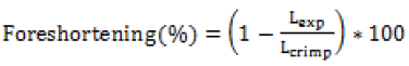 (1)
(1)
Where, Lexp and Lcrimp are the length of the stent after crimping and expansion, which gives an idea to a clinician to choose the right length according to vessel support length required during an angioplasty procedure.
(b) MCUSA (maximum circular unsupported surface area) and cell area: Cell area controls the tissue prolapse between the stent struts when a stent is expanded inside the vessel. MCUSA is the maximum possible unsupported circular area reported as the radius of the circle in mm, as shown in Figure 1.
(c) Recoil (ASTM F2079-09): Minimal stent recoil is a desirable feature of a stent because it minimizes the maximum diameter to which a stent must be expanded to achieve its final relaxed diameter. Practically excessive expansion of the artery into which the stent is to be implanted may cause tissue damage resulting in a poor immediate or long-term outcome. A lower value during crimping is desired for proper securement on the balloon. Hence it needs a delicate optimization for each material or grade of material.
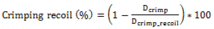 (2)
(2)
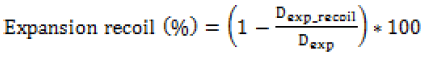 (3)
(3)
Where Dcrimp_recoil and Dexp_recoil is the diameter of the stent after crimping and expansion recoil.
Figure 6 shows nine stent model parametric (mp’s) geometries generated by changing the respective stent design parameters (dp’s) as outlined in Table 2. A finite element model is made similar to the previous unit ring parametric study. Material properties of PLLA (E=3.4 GPa, μ=0.33, and σy=60MPa) is used in the simulation. A node on each of three bottom connectors was constrained to move in radial direction only. Diameters and lengths were obtained from the simulations to calculate the recoil and foreshortening. Cell area and MCUSA were then extracted from 3 mm diameter geometry for the sake of parametric design comparison.

Figure 6: Stent geometry (model parameters or mp’s).
Parallel plate compression (Crush test)
A stent may undergo compression during sudden loading and is a secondary condition for a designer to optimize. Here it is reported just for the sake of completeness and a second thought as the compression force might be most relevant in designing a stent for the peripheral region. Deployed mesh geometry after Step-4 is imported to ABAQUS for parallel plate crush simulation. Two analytical plane surfaces were created to simulate parallel plates, initially separated by 3.3 mm vertical distance. Surface to surface, finite sliding frictionless contact, enforced by a penalty algorithm was imposed between the compressing plates (master) and the outer surface of the stent (slave). Only the vertical displacement of the upper plate was allowed. Vertical down displacement of 2.2 mm was given to the upper plate, and lower plate remains fixed, thereby compressing the stent until a minimum clearance of 1.1 mm with respect to the lower plate is achieved as shown in Figure 7.

Figure 7: Parallel plate crush test model.
Connector design (Flexibility)
Three connector designs (Connector-1, Connector-2, and Connector-3) were tried, and their shapes are shown in Figure 8 (a)-(c). A 3 mm, diameter CAD model, was made and crimped to 1.2 mm outer diameter as in unit ring parametric study. The deformed crimped mesh geometry was then again imported into ABAQUS for flexibility analysis.

Figure 8: Connector designs (a) Connector-1 (b) Connector-2 (c) Connector-3.
The response of a unit cell for three different connector design has been simulated to study the flexibility of stent according to the literature [20,21], as it is easy to use and comprehend. A unit cell model gives a close idea of full-length stent flexibility [22]. Two reference points (RP-1 and RP-2) are created on both ends of the model, as shown in Figure 9 (a). These reference points are tied to nodes on the crown at their respective ends using the multipoint beam constraint (yellow lines), as shown in Figure 9 (b). RP-1 is constrained to not move in X, Y, and Z-directions. RP-2 is constrained to move only in X-direction, and its rotation about X-axis is prohibited. A smoothly increasing equal and opposite moment varying from 0 to 0.5 N-mm is applied to these reference points resulting in bending about the Y-axis.

Figure 9: Flexibility (a) Model (b) Constraints.
Applied moment (M) vs. curvature index (χ) graph is plotted to compare the flexibility of different connector designs. Where the
Curvature index (χ)=2(ϕ/L) (4)
In which φ is the deformation angle, and L is the length of one unit of the stent, as shown in Figure 9 (a). A smaller area under this curve indicates better flexibility of the stent under simulated design study.
Simulation results are discussed in this section. The effect of change in unit ring parameters is discussed in Effect of change in unit ring or hoop parameters. Stent mechanical performance has been discussed in design performance. Parallel plate crush simulation results and flexibility results are presented in Parallel plate compression and flexibility, respectively.
Effect of change in unit ring or hoop parameters
The radial force is applied on the outer and inner surface of a stent through crimper and balloon to crimp and expand the stent. ASTMF3067-14 describes the method to test the radial force Vs. Diameter curve for a balloon-expandable stent and complete loading and the unloading cycle can be divided into four segments:
(1) Initial loading,
(2) Loading with increased plasticity,
(3) Unloading, and
(4) Return.
Initial loading represents the response of the stent from the starting point of contact to full contact with fixture loading surfaces. Radial force starts to increase linearly after full contact and stent begins to deform elastically or combination of elastic and plastic deformation. The slope begins to flatten out and load increases at a decreasing rate with greater compression as the plastic deformation increases. Stents need to be compressed to a greater diameter for crimping. The stent is unloaded after maximum compression required. The unloading also follows a linear trend like initial loading curve. An offset line parallel to this unloading line translated through a fixed distance towards the loading line is drawn. The intersection of this translated offset line with the loading curve is considered the radial strength of the stent of the cut stent. The difference between the loading line x-axis intercept and unloading line x-axis is the diametric plastic deformation of the stent due to compression.
Figures 10 -13 shows the plots of radial force Vs. the outer diameter of a unit ring during various steps as estimated from the finite element simulation on different geometrical models (dp1-9). Reaction forces on cylinder nodes are summed in the radial direction to obtain the radial force. Radial force during crimping is plotted as positive, and during expansion, it is plotted as negative to show the direction. Radial strength is calculated and summarized in Table 4 using the described procedure.
| dp# | Dcrimp_recoil (mm) | Dexp_recoil (mm) | Radial Strength (N) |
|---|---|---|---|
| dp1 | 2.02 | 3.06 | 1.03 |
| dp2 | 2.03 | 2.97 | 0.65 |
| dp3 | 2.2 | 2.81 | 0.54 |
| dp4 | 2.24 | 2.82 | 0.56 |
| dp5 | 2.22 | 2.83 | 0.57 |
| dp6 | 2.43 | 2.71 | 0.28 |
| dp7 | 2.79 | 2.8 | 0.2 |
| dp8 | 2.21 | 2.75 | 0.36 |
| dp9 | 2.79 | 2.8 | 0.29 |
| dp10 | 2.14 | 2.82 | NA |
| dp11 | 2.07 | 2.83 | NA |
Table 4: Effect of design parameters (dp’s) on radial strength and recoil.

Figure 10: Radial force Vs. Outer diameter (Effect of change in Amplitude(A)).

Figure 11: Radial force Vs. Outer diameter (Effect of change in Length(L)).

Figure 12: Radial force Vs. Outer diameter (Effect of change in Width(W)).

Figure 13: Radial force Vs. Outer diameter (Effect of change in Thickness(T)).
Effect of Amplitude (A): As shown in Figure 10, Radial force during crimping, as well as the expansion of the crown ring increases as the amplitude (A), decreases. A lower radial force during crimping and dilation is desired to minimize the stresses on stent and artery. Therefore, the amplitude (A) should be as high as possible, or it should be optimized according to the starting diameter of a tube.
Effect of strut length (L): As shown in Figure 11, change in strut length has a negligible effect on the radial force during crimping and expansion, as it only connects the two crowns rings and undergoes rigid body transformation only. Therefore, this parameter is not found to be significant for the ring design.
Effect of strut width (W): As shown in Figure 12, the radial force increases significantly with the slight increase in the width. Therefore, a higher width is required for higher radial force. However, the higher crossover profile and stresses imparted to the artery during dilation is a limitation in using a higher width of stent crown and therefore a material property optimization is required to minimize the width of the crown. This may lead to further optimization based on material property as desirable to an artery or the plaque to remain opposing a stent with minimum force.
Effect of strut thickness (T): As shown in Figure 13, the radial force decreases drastically with the decrease in strut thickness. Therefore, a higher thickness of the struts is desired, but then it can restrict blood flow and create turbulences in the blood flow near the struts leading to severe complications. For achieving minimum wall thickness, the material properties that are more relevant in particular are the radial stiffness, which has to be optimized for a given material grade.
Effect of material properties: Radial force Vs. diameter is plotted in Figure 14 (a) for polymer Case 1-3, to describe the effect of material properties. The decrease in the yield strength lowers the radial force requirement to crimp, whereas an increase in Young’s modulus increases the radial force as well as stiffness. This result suggests that the crimping must be performed at a higher temperature closer to the glass transition temperature (Tg) as the modulus and yield are lowest at Tg of any polymeric material, whereas this is not a requirement for any metal-based stent.

Figure 14: Radial force Vs. Outer diameter (Effect of Material Properties) (a) Polymer (b) Metal.
Radial force Vs. diameter is plotted in Figure 14 (b) for metal Case 4 and Case 5. The radial force is higher for the metal ring during crimping (1.5-1.8 N) and expansion (2.2-5 N) as compared to a polymer ring (0.5-0.8 N), although the dimensions of the metal ring are lower compared to polymer ring as shown in Figure 14 (b). It means that radial force required to crimp and deploy the metallic stent is very high as compared to the polymer stent, which might damage the stent surface and artery during crimping and deployment. However, the lower profile (width and thickness) of metallic stents (0.06-0.08 mm) benefits in avoiding flow disturbances and injure to the lesser areas of the artery during deployment. A better idea of forces on the arterial system will help in designing a polymeric stent with an optimum radial force and optimum profile as it is still not fully understood what a plagued and calcified artery needs.
Radial strength: Here, stress-strain history is considered to calculate the radial strength. Figure 15 depicts a comparative idea about the expansion recoil diameter and the radial force it can resist before collapsing for the nine design variables.

Figure 15: Radial force Vs. Outer diameters (Radial strength).
Radial strength and recoil diameters after Step-4 are summarized in Table 5. In this graph, dp1 (minimum amplitude, A) has the minimum recoil with the highest radial strength. A comparison of dp1, dp2, and dp3 shows that the radial strength decreases with the increasing amplitude, but recoil increases with increasing amplitude. Comparing dp3, dp4, and dp5 to study the change in length, one can see that strut length has little effect on the recoil and radial strength. Comparison of dp5, dp6, and dp7 shows that radial strength decreases with a decrease in width (W). Comparison of dp5, dp8, and dp9 shows that radial strength decreases with the decrease in thickness (T). The same trend is observed as in no stress-strain condition. Based on the recoil and radial strength, dp1 or dp2 meets the requirement of supporting the lumen. Also Comparing radial strength in Table 4 and Table 5, one can see that radial strength considering the loading history is less than without considering the loading history.
| S.no | Variables | dp1 | dp2 | dp3 | dp4 | dp5 | dp6 | dp7 | dp8 | dp9 |
|---|---|---|---|---|---|---|---|---|---|---|
| 1 | Dexp_recoil (mm) | 3.05 | 2.99 | 2.74 | 2.82 | 2.82 | 2.72 | 2.83 | 2.77 | 2.72 |
| 2 | Radial Strength (N) | 0.8 | 0.48 | 0.46 | 0.51 | 0.49 | 0.26 | 0.18 | 0.16 | 0.1 |
Table 5: Radial strength (considering stress-strain history).
von Mises stress and true strain (LE): The following Figure 16 (a)-(c) shows the von Mises stress, PEEQ (plastic strain) and strains (true strain) during various steps for dp1.

Figure 16: (a) von Mises stress (b) PEEQ (c) Strain (d) Location of maximum stress & strain
Where True strain (LE)=1+e(nominal strain) (5)
Maximum stress and strains occur at the inner radius of the crown, as shown in Figure 16 (d). Figure 16 (a) shows that stresses increase during crimping up to yield stress (60 Mpa) at the inner radius of the crown. Maximum compressive strain occurring on struts during crimping is 0.3 mm/mm (30%) for dp1, and the maximum tensile strain during expansion is 0.16 mm/mm (16%) for dp1 as observed in Figure 16 (c). Based on simulation; it can be concluded that polymer material should have a minimum break at an elongation of 30%, commonly available with metals. The stresses at loading and unloading are in the range of 0-60 MPa as the material model used is perfect elastic-plastic. Furthermore, detailed stress-strain curve of material is required for any blend or copolymer for more comprehensive stress-strain analysis. Stresses reach yield strength during the crimping and get relaxed during the recoil. The radial strength of a metallic stent is attributed to plastic deformation or yielding at the crown. The commonly used PLLA is a very brittle material (break occurs at very low strain value <5%). The blending of pure PLLA can be done with other polymers such as PCL (polycaprolactone) or PGA (polyglycolide) to improve the ductility of the material. Starting tube diameter should be adjusted to minimize the stress and strains. Safe vascular stent application requires rapid expansion of the stent to minimize the risk of procedural ischemia; this requires investigation into ratedependent material properties. Though high expansion speeds can be achieved with a metallic stent as it can sustain abuse, it is not necessarily feasible with existing biodegradable polymeric stents due to the viscoelastic material behavior. Therefore, there is a need to use the temperature and strain rate, dependent material model. Also, the lower the recoil, higher is the residual stress and strain as the material model used is a perfect elastic-plastic model. A stiffer structure (high radial force) will undergo more plastic deformation (more stresses) in the loading cycle and less recoil but may not be feasible due to failure when subjected to such high stresses and strains.
Effect of starting diameter: In Figure 17 (a) it can be seen that crimping recoil increases with starting tube diameter, but the expansion recoil is the same irrespective of staring tube diameter. Which suggests that crimping deformation can be reduced by choosing smaller tube diameter although radial force during expansion increases with a decrease in initial diameter. Making smaller diameter polymer tubes may be manufacturing and extrusion challenges. Also, the maximum crimping radial force has close values for all three initial diameters though the stiffness varies.

Figure 17: Effect of tube diameter (a) Radial Force (b) Stress (b) Strain.
The strains and residual stresses after Step-2 and Step-4 are dependent on the starting tube diameter and are recorded to be maximum during the crimping, as shown in Figure 17 (a) and (b). von Mises stresses after Step-2 are higher for higher initial diameter and stresses after Step-4 is lower for higher diameter. Maximum strains (compressive) is observed during crimping and is higher for higher diameter and lower (tensile) stress for higher diameter after Step-3. Strain after Step-2 and Step-4 are lower for lower diameter and higher for lower diameter. Which suggests that choosing a lower diameter tube will decrease the residual stress after crimping relaxation (Step-2) but will increase the residual stress after expansion relaxation (Step-4). Similarly, a small diameter stent tube will decrease the compressive strain during crimping but will increase the tensile strain during expansion. So, an optimum diameter of the tube can be selected for a given material (allowable stress and strain).
Effect of crown shapes: The study in this section demonstrates a methodology to compare and design different shapes of the crown in the ring of the stent. In Figure 18, the radial force is plotted for four different crown shape designs. Preliminary study shows that Design-2 has the least recoil during crimping and expansion. Radial forces are found in a narrow range during the crimping, and they vary between 0.6-1 N during expansion. Design-1 has the lowest radial force during crimping and expansion. Design-3 and Design-4 have intermediate values. It is observed that a small change in radius can change the performance to a great extent, which should be studied and optimized for any design. Very preliminary observations are discussed hereunder based on Figures 19 and 20. Which shows the von Mises stresses and true strain during step1-4 for Design1-4. Stress and strain during the various steps are also summarized in Table 6.
| S.no | Designs | Max Stress (MPa) | Max Strain (%) | ||||||
|---|---|---|---|---|---|---|---|---|---|
| Step-1 | Step-2 | Step-3 | Step-4 | Step-1 | Step-2 | Step-3 | Step-4 | ||
| 1 | Design-1 | 60 | 53.45 | 60 | 40.20 | 9 | 7 | 2 | 3 |
| 2 | Design-2 | 60 | 51.94 | 60 | 38.66 | 11 | 8 | 3 | 2 |
| 3 | Design-3 | 60 | 46.20 | 60 | 43.2 | 8 | 6 | 3 | 2 |
| 4 | Design-4 | 60 | 60 | 60 | 47 | 10 | 3 | 6 | 3 |
Table 6: Maximum stress and strain for Design 1-4.

Figure 18: Radial force Vs. Outer diameters (Effect of crown design).

Figure 19: von- Misses stresses (Mpa).

Figure 20: True strain (mm/mm).
Comparing between Design-1 and Design-2, it is observed that increasing the width at crown radius results in the less plastically deformed region at radius and struts bends where the crosssection area is lower. Which suggests that bending locations can be distributed so that there are uniform stress and strain through the struts and use of the strength of the material is optimized. The minimum stress and strains after step-3 are lowest for Design-3. The minimum stress and strains after step-4 are lowest for Design-2. It also suggests two methods to minimize stresses and strains, i.e.
(1) Width changes (Design-1 and Design-2) and
(2) Tweaking fillet or radiuses (Design-3 and Design-4).
A permanent yield can be seen on inner radius and inner diameter for Design 1 and 3. But for design 2 and 4 yielding occurs at the bend radiuses as they are the region of maximum stresses. During expansion, maximum stresses occur at the inner radius for all the Designs 1-4. Maximum strain during crimping (Step-1) is found to be maximum for Design-2 and minimum for Design-3. Strains after Step-2 is maximum for Design-2 and minimum for Design-4. Strains after Step-3 is maximum for Design-4 and the minimum for Design-1. There is no significant variation in residual strains after Step-4 for all the designs. So, Design-4 is better from the point of residual strains as they are distributed due to curved regions. Design-3 is better for minimum stresses after crimping recoil. Design-2 is better for minimum stresses after expansion recoil. Such design prediction is not final as their parameter values can change the performance.
Design performance (polymer stent)
Table 7 summarizes the effect of crown design parameters (dp’s) on stent performance. Model parameter (mp’s) 1-9 denotes the stent geometry obtained by using the design parameters (dp’s) 1-9. A decrease is a crown radius of mp1-9 is noted due to the accommodation of three straight connectors of 0.08 mm width. A gap of 0.5 mm is kept constant between two crowns in the longitudinal direction. A minimum gap should be chosen to accommodate the closing of struts and flexible connector design. Cell area and MCUSA increase as this gap increases. More number of crowns can be added, which will decrease the crossing profile in a crimped state. Stent length and cell area increases as amplitude increases and width decreases. Width of stent struts is dictated by its radial strength requirements though. A smaller amplitude will provide better radial strength and tissue support but will have a failure during crimping as stresses will be higher. MCUSA is found to be more sensitive to the gap and crown radius.
| Model | Parameters | Results | ||||||
|---|---|---|---|---|---|---|---|---|
| Crown radius (mm) | Stent Length (mm) | Crimp Recoil (%) | Expansion Recoil (%) | Foreshortening (%) | Cell Area (mm2) | MCUSA (mm) | ||
| mp1 | dp1 | 0.3 | 2.95 | 25.38 | 7.81 | 3.72 | 2.75 | 0.86 |
| mp2 | dp2 | 0.31 | 3.55 | 31.9 | 10.52 | 6.13 | 3.23 | 0.87 |
| mp3 | dp3 | 0.34 | 3.74 | 28.57 | 17.52 | 3.26 | 3.72 | 0.87 |
| mp4 | dp4 | 0.37 | 4.15 | 40 | 15.15 | 2.99 | 4.08 | 0.84 |
| mp5 | dp5 | 0.28 | 4.15 | 40.22 | 14.24 | 3.56 | 3.77 | 0.93 |
| mp6 | dp6 | 0.28 | 4.1 | 51.3 | 18.82 | 3.16 | 4.04 | 0.97 |
| mp7 | dp7 | 0.28 | 4.08 | 50.56 | 15.1 | 2.79 | 4.16 | 0.99 |
| mp8 | dp8 | 0.28 | 4.15 | 30.25 | 10.27 | 6.66 | 3.76 | 0.93 |
| mp9 | dp9 | 0.28 | 4.15 | 41.08 | 17.87 | 3.95 | 3.76 | 0.93 |
Table 7: Stent model parametric (mp’s) simulation results.
The radial load (y-axis) expressed as a force normalized by the initial stent length (N/mm) Vs. outer diameter (x-axis) (mm) of the stent is plotted in Figure 21. In Figure 21 (a) radial forced during Step- 1 (crimping) and Step-2 (crimping recoil) is plotted. In Figure 21 (b) radial forced during Step-3 (expansion) and Step-4 (expansion recoil) is plotted.

Figure 21: Radial force (N/mm) Vs Outer diameter (a) Step-1 & Step-2 (b) Step 3 & Step-4.
Comparison of the plot of mp1, mp2, and mp3 in Figure 21 (a) and (b) suggests that radial force increases with the decrease in amplitude. Comparison of mp3, mp4, and mp5 suggests that negligible change in radial force occurs with a decrease in strut length. Comparison of mp5, mp6, and mp7, one sees that radial force further decreases with a decrease in width. Comparing mp5, mp8, and mp9, one sees that radial force decreases with a decrease in thickness. These confirm our earlier observations that radial forces are dependent on hoop parameters only.
Figure 22 shows the von Mises stresses and parameters measured from the finite element model (mp3). The resulting parameters, such as recoil and foreshortening, were calculated from these parameters (Dcrimp, Dexp, Lcrimp, Lexp), as shown in Figure 22. Stress concentration and relaxation can be seen in the above Figure 22 during the various loading cycle. Stent failure occurs at the inner radius of the crown during crimping and deployment, hence inspection of these areas for defect must be done before packaging of stents. Also, they are the most critical areas of the structure where fatigue failure also occurs and is known for metallic stents. Even the failure at such one location will lead to stent instability and sudden collapse, which may be fatal and increases the risk of the polymeric stent.

Figure 22: von Mises stresses and performance evaluation.
Parallel plate compression (Crush test)
The von Mises stress in the deformed configuration and relaxation step for mp3 is shown in Figure 23 (a) and (b). Maximum stresses can be seen to occur in the vertical and horizontal opposing struts, as the plates compress the vertical strut come closer and horizontal struts go apart. In the unloading step, a recovery of diameter can be seen for some mp’s.

Figure 23: von mises stresses (MPa) during crush test (mp3) (a) Loading (b) Unloading
Force versus displacement curves of stents (mp1-9) for parallel plate crush tests is plotted in Figure 24.

Figure 24: Force Vs. displacement (Crush Test).
Crush strength is also summarized in Table 8.
| mp# | 1 | 2 | 3 | 4 | 5 | 6 | 7 | 8 | 9 |
|---|---|---|---|---|---|---|---|---|---|
| Force (N) | 0.360 | 0.318 | 0.289 | 0.356 | 0.360 | 0.308 | 0.080 | 0.124 | 0.061 |
Table 8: Crush strength.
From above Figure 24 and Table 8, it is found that crush strength follows the same trend as the radial force. Comparing the plot of mp1, mp2, and 3, one can see that the crush force increases as amplitude decreases. Comparing the plot of mp3, mp4, and mp5, length does not affect the crush strength significantly. Comparing mp5, mp6, and mp7, one sees that the crush strength decreases as width decreases. Comparing mp5, mp8, and mp9, crush strength decreases as thickness decreases.
Flexibility (Bending)
Figure 25 (a)-(c) shows the crimped state of a stent. Figure 26 shows the von Mises stresses in the deformed state of a stent. The flexibility of a stent is determined by the amplitude and design of the links/connectors. During bending, links on the outer radius get stretched, and links on the inner radius get compressed. Links on compression side may come into self-contact after reaching a certain bend curvature. Such a contract, which depends on the specific design of the links, can result in increased resistance to bending and should be avoided. Maximum stresses occur at the connector during bending, as seen in Figure 26.

Figure 25: Crimped state (a) Connector-1 (b) Connector-2 (c) Connector-3.

Figure 26: Flexibility (Deformed state) (a) Connector-1 (b) Connector-2 (c) Connector-3.
A plot of the moment versus the curvature index is shown in Figure 27.

Figure 27: Moment Vs. curvature index.
From the above trending graph, the least flexibility and less deformation angle of Connector 1 can be seen compared to Connector 2 and 3 as it has a higher area under the curve and lower curvature index. Similarly, Connector-3 has better flexibility compared to Connector-2. Also, the deformation angle for Connector-3 is larger than Connector-2, allowing to reach lower curvature bends.
A few potential limitations need to be considered with respect to our study. The material model used in the simulation is assumed to be perfect elastic-plastic, so a comparative stress-strain analysis during crimping and expansion is not reported. A rigid cylinder is used to model the expansion, but a balloon model will capture the realistic expansion performance such as dog boning (end flare), which will be addressed in our future work [23]. Flexibility of a unit cell is reported but such a physical testing setup is not feasible. So, a three-point bending simulation should be done to evaluate the flexibility of full stent structure to compare with testing results. Total simulation time for running all the cases is approximately 200 hours (46 cases). Simulating more parameter combination and cases requires more computational resources, which is also a limitation.
This work demonstrates that the finite element simulation is a reliable tool to study the effect of change in geometrical and material parameters on the performance of a stent. This study offers a new perspective to evaluate stent designs based on stress, stain, and radial force. High radial forces are associated with high stresses and strains during crimping and expansion. Similar studies in literature focus on stress-strain, recoil, or radial strength without considering the stress-strain history [24]. Most parametric studies available in literature reports the effect of design parameters on the mechanical performance of metallic stents [25-27], but such investigation has not been reported for polymer stents. In this study, a methodology for designing of a polymer-based stent is developed, and the difference between polymer and metal stent design philosophy is also discussed. Low amplitude and high width and thickness are desired for a high radial strength of polymer-based stent given the low modulus of polymers. But lower amplitude results in high radial force required during the crimping and non-uniform crimping and migration of struts is observed in simulation for stiffer structure (lower amplitude, higher width, and thickness). Also, a higher width and thickness may increase long-term complications such as NH (neointimal hyperplasia) and inflammation [28]. These simulation results should be correlated with physical testing to make the model more accurate. Based on radial strength and recoil dp1 or dp 2 with Connector-3 is selected for further testing, though the effort should also be to achieve lower width and thickness as in metallic stents through material property enhancement. From simulation studies, an optimum value of design parameters for a particular material can be chosen to achieve adequate radial strength, radial stiffness, and minimum crimping profile to optimize the design before manufacturing.
Major challenges in the development process and design concepts are being understood in the modeling of a polymer stent based on the material properties. This study encourages us to think of a polymeric structure which can be crimped to a lower profile and can be expanded to deploy without causing much stresses and strains to the material while minimizing sharp bends or stress concentration regions. The hoop strength of the tube should be increased by manufacturing innovations to improve the mechanical performance of the stent. Many innovative stent designs have been explored in the literature, but most of them are not a clinical reality yet. A computation model will be a great tool in minimizing the number of testing and trials. The following points can be highlighted based on simulation studies.
1. Starting diameter to manufacture the stent should be chosen according to the intended diameter of the lumen to be treated.
2. Radial forces, radial strength, recoil, stress-strain, MCUSA, cell area, crimping profile and flexibility can be optimized using geometrical parameters such as amplitude, length, width, thickness, crown and connector design.
3. Yield strength/ultimate strength is the criterion for metal stents, but allowable elongation/strain should be considered for polymer stents design.
4. It is always desirable to design and analyze a stent based on material properties before manufacturing and clinical testing.
The study is supported by a generous grant of MHRD (Ministry of Human Resource Development) and ICMR (Indian Council of Medical Research) under the IMPRINT (Impacting Research Innovation and Technology) program of Government of India.
Citation: Avinash K, Ramya A, Pooja B, Priya V, Naresh B (2019) Design Methodology of a Balloon Expandable Polymeric Stent. J Biomed Eng Med Devic 4:139. doi: 10.35248/2475-7586.19.4.139
Received: 24-Jun-2019 Accepted: 22-Jul-2019 Published: 29-Jul-2019 , DOI: 10.35248/2475-7586.19.4.139
Copyright: © 2019 Avinash K, et al. This is an open-access article distributed under the terms of the Creative Commons Attribution License, which permits unrestricted use, distribution, and reproduction in any medium, provided the original author and source are credited.