International Journal of Advancements in Technology
Open Access
ISSN: 0976-4860
ISSN: 0976-4860
Research Article - (2017) Volume 8, Issue 3
A polymer-ceramic composite material was modelled in the MatLab software, and developed for low-temperature applications. No gasses were emitted during the manufacturing process of this composite. The objective was to develop a uniformly dispersed, interwoven, and reinforced fibre’s structure, resulting in a fiber pyro expanded perlite/ epoxy composite. The material does not cause immediate chemical reactions, either with the severe nor the soft matrix of epoxy resins. Mechanical and physical characterizations of the material were described herein. The thermal conductivity of the material was calculated by the Mixture Rules method and experimentally by Method SAM, finding a value of 0.284 W/mK. The main application proposed for this material is for thermal insulation purposes at cryogenic temperatures in the industry.
<Keywords: Fiber expanded perlite, Epoxy, Thermal conductivity, Low-temperature applications
Composite materials have been the subject of constant interest for many specialists over the last decades. Innovations in the composite area have allowed for significant weight reduction in structural design. Composites offer many advantages over metal alloys, especially in applications where high strength and stiffness to weight ratio is a concern. Also, composites have an excellent fatigue property and corrosion resistance. However, these materials may present some disadvantages such as low fracture toughness and moisture absorption. Composites are used in different fields since these materials can be selected to give unusual combinations of properties. For example, reliability is of great importance in low-temperature applications, such as in the cryogenic area. Thermal conductivity, tensile strength, and compressive strength are critical composite properties, which are primarily influenced by fiber reinforcement. The selection of the matrix is important when trying to find the appropriate material. Epoxy resins have been widely employed in cryogenic engineering fields. Since conventional epoxy resins would readily crack at low-temperature, it is important to select the appropriate epoxy resins. The class of epoxy resin utilized to make the composite material is used as the matrix. The reinforcement uses fibers such as boron, alumina, aramid, S-glass, E-glass and carbon in applications relate to cryogenic engineering fields [1].
One of the advantages of using composites is that the resulting material may be stiffer and stronger, yet lighter and with a low thermal conductivity compared to conventional materials for similar applications. These properties depend on the type of the component and the quantity in the composite. Nowadays, these materials are used in the cryogenic industry as cryomagnetic [2], and as a thermal insulator [3]. The composite developed from ceramic/polymer exhibit excellent dielectric and mechanical properties and low thermal conductivity [4]. The epoxy resins are resistant to low temperatures and have good mechanical properties because these properties are employed as a matrix forming the composite materials in cryogenic engineering. Some reports on composites based on perlite are presented in the literature, which is to improve the properties of some polymers [5].
Based on the above, this paper presents the developed of a composite material perlite/epoxy proposed as a thermal insulator. This is using the excellent properties of thermal insulation that the perlite exhibits.
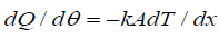
The heat transfer mechanism by temperature gradients can be calculated by using the equation:
 (1)
(1)
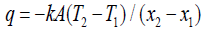
The amount of heat flowing through an area A, in the time, dθ, is dQ, and the constant of proportionality between them is the thermal conductivity, k. When the system is in steady state, the heat flow takes discrete values. Therefore, the temperature at each point is independent of the time. This consideration allows that the heat equation can be integrated for different geometries. For example, where there is a flat wall the equation (1) takes the form:
 (2)
(2)
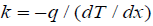
According to the geometry of the system, different expressions may be derived. We are expressing k regarding the Fourier’s law.
 (3)
(3)
This equation shows that when there is a temperature gradient, the heat flow rises with an increase in the thermal conductivity. For instance, the thermal characteristics of the composite materials are dependent on the orientation of the fibers [3]. In this regard, a mathematical model that has been successful for predicting the thermal conductivity of composites is the Mixture Rules [6]; it takes into account the amount and fiber orientation in the composite. The Mixture Rules is a mathematical model to determine the thermal conductivity of multidirectional composites of simple geometry. If the heat flow is parallel to the plane of the layer, this is equivalent to a parallel electrical circuit, each layer has the same thermal gradient, and most of the heat flow is through the best conductor.
 (4)
(4)
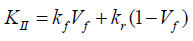
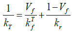
\In assessing the influence of the conductivity in a direction, it is necessary the equation (4). Where KII is the thermal conductivity of the composite, kf is the thermal conductivity of the fiber, kr is the thermal conductivity of the resin, Vf is the volume fraction of fibers and (1- Vf) represents the volume fraction of resin.
The series electrical resistance analogy with an electrical circuit in which the components are connected in series, Thornburgh and Pears derived the follow equation [7]:
 (5)
(5)
Where represents the thermal conductivity of the fibers in the cross section. Neglecting the presence of empty spaces in the material, the modified form of the Mixture Rules [6]:
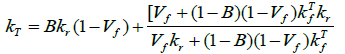 (6)
(6)
B is the volume fraction of the resin. In this investigation was used for the distribution of perlite fiber and resin, the Cugnet’arrangement as shown in Figure 1. The perlite´s fibres are oriented from 0º to 45º; this distribution can support the thermal behavior of the composites at cryogenic temperatures [3].

Figure 1: Arrangement of fibers in the composite material [3].
The mathematical model (equation 6) was solved using the MatLab software; with the following values.
The thermal conductivity of perlite 0.047 W/mK [8], the thermal conductivity of resin 0.19 W/mK [9], and B is the volume fraction of the resin which is assumed to present a continuous path for heat flow [6]. With these values solved in MatLab, the thermal conductivity behavior of composite versus the fraction volume of resin is depicting in Figure 2.

Figure 2: Volume of fibers vs. thermal conductivity fraction.
Figure 2 shows a decrease of the thermal conductivity of the composite when the fraction of the fibres of perlite changes. It can be seen a good relation of fibre’s and resin; this represents a composite with excellent properties of thermal insulation and good mechanical properties.
In this section, we introduce the experimental development for the manufacture of the material composite.
Manufacture of expanded perlite fibres
Expanded perlite is an acidic volcanic rock, the perlite not expanded has a density close to 1100 kg/m³ and a thermal conductivity of 0.047 W/mK [8]. While the expanded perlite has a density between 30 and 150 kg/m³, and its chemical composition (percentage by weight) is showed in Table 1. The perlite is a product crushing and has sizing operations until a perlite, with a specific gravity around 2.34 [10]. It can be expanded 7-16 times its original volume when heated in a temperature range of 700 to 1200°C. It has a porous structure consisting of mesopores and macropores [11,12].
| Raw material | %w |
|---|---|
| SiO2 | 71.58 |
| Al2O3 | 13.23 |
| K2O | 4.02 |
| Na2O | 3.36 |
| CaO | 2.12 |
| Fe2O3 | 1.83 |
| MgO | 1.04 |
| H2O | 2.5 |
| Total | 99.68 |
Table 1: Chemical composition of perlite [9].
The dimensioning of the perlite is carried by a sieve USA Standard Testing Sieve ASTME-11 # 100, to obtain a particle with a size of 150. In addition, with a high-temperature heat treatment (1200°C) is possible to eliminate porosity and to produce a good sintered powder [13]. The technique involved in the heat treatment requires entering an oven the mold mullite with the powder perlite. After weighing the required amount of pearlite proceeds to place on each of the channels in the mold mullite it is necessary to work detail in the uniformity over the mold to obtain whole and continuous fibers. Mullite molds are used because of a refractory material resistant to high temperatures and inert perlite [14]. The diameter of the fibers depends on perlite melt index, and this, in turn, is controlled by the temperature composition, and extent of the space between rows desired [13].
Once finished for the fibers baking time is necessary to allow natural cooling of the mold and fibers, to a room temperature to remove the already formed fibers. It avoids the thermal shock that could damage the mold or modify treatment outcomes on perlite. Finally, the entire procedure performed to manufacture fibers pyro-expanded perlite is expected reinforcing fibers with the characteristics as a: excellent mechanical resistance, excellent thermal and electrical insulation, low density, non-combustibility, dimensional stability. Fibers pyro expanded pearlite formed by the process described in this section is shown in Figure 3.

Figure 3: Fiber pyro expanded perlite.
Because the control conditions and manufacturing are minimal compared with the high-tech process, it is possible to obtain fibers of different lengths as it is dimension it is subject to various factors; thus it is necessary to handle the fibers with precision and care enough to keep them with the greatest possible length.
Epoxy matrix
To form the epoxy matrix, 50 ml of diglycidyl ether of bisphenol-A (DGEBA) was poured into a container 100 ml of Diethylenetriamine (DETA) [15] it was added slowly, the solution was stirred with magnetic equipment to achieve a homogeneous mixture free of bubbles. During the process, the mixture gradually changed color from light yellow to orange. The thermosetting required was achieved with DGEBA and was placed in a vacuum for 10 minutes.
Preparation of the composite
For the formulation of the composite material, it is necessary to incorporate the constituents in a vacuum. The fibers formed after thermal treatment were arranged on the surface of the Polytetrafluoroethylene (PTFE) mold, one layer at the time with orientations 0º, 45º, 90º, with orientation from 0º ± 45º, after each layer of the fibers was poured a layer of resin was applied, until the desired configuration was reached. The material was dried for 24 hours and then removed from the PTFE mold. With this proposed method, the composite formed is free of bubbles; one panel finished is showed in Figure 4.

Figure 4: Arrangement of the fibers on the surface of polytetrafluoroethylene (PTFE) mold, composite material.
Thermal conductivity meter
The composite material was measured experimentally in the Thermal Conductivity Meter TK04 by the Method SAM with the standard ASTM D5334-08 [15]. In this method is shown that the approximation function ka(t) approaches to the real thermal conductivity value k the better, the greater time where the maximum ka(tmax) of the curve ka(t) is located. The method use a logarithmic measure for the position of the maximum, (the logarithm of the time tmax where the maximum is located) LET value [15] the TC-Diagram relates the LET values of all solutions belonging to the heating curve to their thermal conductivity values. All data points should line up to form a smooth asymptote, whose asymptotic value (i.e., the solution with the highest LET at the top of the curve) is the best solution and result of the measurement. The bottom axis shows absolute thermal conductivity values, the top axis has a percent scale whose zero point is the best solution. The range of ±5% is highlighted.
LET = ln (extreme time) = ln (tmax) (7)
If approximation has a high LET value, this means that the measured heating curve from which it was calculated is as undisturbed, from the resulting heating curve to composite (Figure 5). The results obtained from the tests: thermal conductivity (TC) = 0.284 W/mK and LET = 57.0.

Figure 5: TC-diagram to polymer-ceramic composite that relate the LET values of all solutions belonging to the heating curve to their thermal conductivity values.
Density and thermal conductivity of the resin
The pycnometer method was used to get the density it was 144.332 kg/m3, the thermal conductivity, was reported as 0.047 W/mK, both the epoxy and the curing agent were EPOMEX, which is identified as YD114 epoxy and curing agent NC566. An infrared was recorded to find the chemical composition of the resin, on ST IR Model Spectrum 100 Perkin Elmer with diamond accessory ATR In. The Spectra was interpreted using the software Analyse-RAMalyze®.
In Figure 6, the IR spectra of the resin absorption spectrum exhibit a strong absorption bands are located at the nitrogen-hydrogen longitudinal vibration that appears in the region between a 3150 cm-1 to 3400 cm-1 characteristic of the amines, and functional group H-N-H between 1600 cm-1 and 1625 cm-1 absorption band, at 740 cm-1 corresponding to the functional group C-Cl. The identity of the resin as Dyglycidyl ether of Bisphenol A molecule (DGEBA), and the curing agent as Diethylentriamine molecule (DETA). The hardness of the composite material resin 80 Shore D it was measured by a durometer model Shore D ASTM D2240. The composite samples were prepared and tested with test Three Point Bend SetUp (40/0678) on the Universal Machine Chatillon LR10K. This test was performed under the following conditions; Jog Speed, 500 mm/min, Load Limit: 6000 N, Preload: 20 N, Span: 0.051 m. Table 2 shows the test results for the three-point composite.

Figure 6: The IR spectra of the resin of composite material.
| Property | Average | Unit |
|---|---|---|
| Temperature | -11.7000 | ºC |
| Maximum load | 68.3760 | N |
| Maximum deflection | 0.0015 | M |
| Maximum effort load deflection | 0.5129 | MPa |
| Young’s modulus of deflection | 8.9542 | MPa |
| Rigidity | 0.2884 | Nm2 |
| Elastic deformation | 0.1556 | MPa |
| Resilience | 0.0008 | J |
| Ductility | 1.4450 | % |
| Tenacity | 0.0035 | MPa |
Table 2: Main results for the composite.
The mechanical test was done using the Universal Testing Machine CHATILLON LR10K. The composite material was submerged in liquid nitrogen before the test. The Young’s Modulus of the resin was 8.576 MPa and its maximum load to rupture was 153.34 N.
A composite for low temperature applications formed by a matrix of epoxy resin and pyroexpanded perlite fibers was modeled, to know the thermal conductivity of the composite was solved the mathematical model (equation 6) in the MatLab software. It was solved in the MatLab program, the thermal conductivity of the composite against the volumetric fraction of the pyroexpanded perlite fiber, the values obtained are in a range from 0.18 W/mK to 0.04 W/mK. For the preparation experimental of the composite was considered the 0.54% volumetric fraction for the resin. The thermal conductivity obtained to the composite was TC=0.284 W/mK and Let=57.0, the Thermal Conductivity Meter TK04 was measured according to ASTM D5334-08. The mechanical properties of the composite were measured, resulting a material resistant to lower temperatures and good thermal insulating properties at low temperatures. The conductivity of different composites at different temperatures is presented in Figure 7, the overlaid red line shows the behavior of the pyro-expanded composite/epoxy perlite obtained in this research. It is noted that it has good thermal insulating. Figure 7 shows the results of the thermal conductivity for different materials used in the cryogenic industry.

Figure 7: Thermal conductivity of commercial composites [1].
Based on this result, we chose a value of 0.54 for the volume fraction of the fibers that predict a value of thermal conductivity of 0.109 W/m K. Thus representing the average value of a material used as a thermal insulator. The work of Shokralla [16] and Hofmann [2] were used to determine the values of the thermal conductivity for the epoxy and for the fibers, respectively. With the results obtained in this research can take advantage of the excellent properties of perlite as a thermal insulation in a composite material and a simple manufacturing method for various applications in the industry [17].
The goal of obtaining a composite material perlite/epoxy to be used as heat insulator was achieved. One of the state of the art contributions is the method for the manufacture of the fibers of the perlite in the form of strips. To get these fibers, a different method for the manufacture of the composite was required. It may be concluded that when comparing the results of the test of three points between the resin and the composite, which for this resin material is what makes the properties of mechanical resistance to the composite. Another achievement was the reduction in the shrinkage of the resin due to the change in temperature. The method of manufacturing shows repeatability in the mechanical properties. This work can configure the basics so that the manufacturer takes the fraction of perlite needed for various applications.
The authors thank the University of Guanajuato for their support in this research.