Advanced Techniques in Biology & Medicine
Open Access
ISSN: 2379-1764
ISSN: 2379-1764
Research Article - (2021)Volume 9, Issue 7
The hip joint secondary to osteoarthritis due to high contact pressure by osteonecrosis of femoral head needs to be considered when performing a preservation hip surgery. In this study, the hip joint contact pressure and load transfer path of femoral head by giving an intertrochanteric curved varus osteotomy with several types of lesions were investigated using a finite element method. The contact pressure decreased and the load transfer path widened after this osteotomy. The intertrochanteric curved varus osteotomy could remove the lesion out of weight-bearing area as well as an effective way to decrease the joint contact pressure.
Joint contact ressure; Curved varus osteotomy; Finite element simulation
Intertrochanteric Curved Varus Osteotomy (CVO) is an alternative option as a preservation hip surgery for the treatment of femoral head necrosis used widely in Asia, removing lesion from the weightbearing portion and decreasing the mechanical effect loaded to the infarction for prevention of collapse in the early stage [1]. Contact stress of hip with femoral head necrosis was elevated as compared to those normal hip joints the reason maybe the lesion within weight-bearing portion of acetabular disrupted the load transfer path of femur, accordingly, the elevated contact pressure subjects to the weakened bony structure of lesion leading to the collapse [2,3]. For preservation hip surgeries, the methods such as core decompression that decreased contact hip joint pressure and the method such as tantalum trabecular metal rods with the metal devices implanted to the area of lesion in situ can prevent the occurrence of collapse, that reconstructed the load transfer path of femur [4,5]. However, the mechanical mechanism of CVO for prevention of collapse has been never studied before. The purpose of the study was to evaluate the contact stress of hip joint and load transfer path of femur after CVO using finite element analysis.
This study was approved by our ethical review committee of the hospital; the Clinical Computed Tomography (CT) data was obtained from a healthy volunteer without any musculoskeletal disease and pathological change of the hip joint.
Simulation of Hip Joint Model with Femoral Head Necrosis
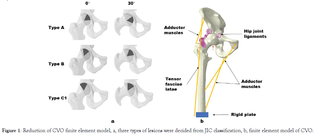
The intact hip joint model was extracted from the CT data by segmenting semi-pelvic and femur with a medical image processing software (Mimics 16, Materialise, Belgium). Then the acetabular and femoral head cartilage were created by filling the clearance gap between the acetabulum and femoral head femoral head necrosis model was simulated based on the Japanese Investigation Committee (JIC) classification [6], [7]. The lesion size was a conoid shape of 60° to represent an early stage without collapse three location-based types of lesions (type A, B, C1) was created from JIC classification (Figure 1a) [8].
Reconstruction of CVO
The method of CVO was refereed from our previous study in this study, just a 30° CVO was simulated without implant for eliminating the effect of implant on the load transfer path of femoral head (Figure 1a) [9].
Material Properties and Boundary Conditions
The hip joint finite element models were meshed with tetrahedral elements, for the element of femur, the heterogeneous materials were assigned using Bonemat 3.2. The lesions, cartilage and ilium were assigned with homogeneous material properties summarized in Table 1. The ground reaction force of 700 N was used to simulate the standing loading condition applied to distal end of the femur, seven muscles around hip joint were modelled as axial connectors the hip capsular ligaments (Superior Iliofemoral, Inferior Iliofemoral, Ischiofemoral, Pubofemoral) were modeled as 1D springs elements The pubic symphysis and sacroiliac joint were fully fixed to prevent translation and rotation, the osteotomy site was bounded, and the contact of cartilage was modeled as no friction (Figure 1b and Table 2) [10,11]. The FE analysis was performed using Abaqus 2019.
| Component | Elastic modulus (MPa) | Poisson’s ratio |
|---|---|---|
| Femur bone | CT values based | 0.3 |
| Pelvis bone | Rigid body | |
| Necrotic bone | 124.6 | 0.152 |
| Articular cartilage | 10.5 | 0.45 |
Table 1: Material properties for the model.

Figure 1. Reduction of CVO finite element model, a, three types of lesions were decided from JIC classification, b, finite element model of CVO.
| Component | Forces(N) | Component | Forces(N) |
|---|---|---|---|
| Adductor longus | 560 | Gluteal minimus | 300 |
| Adductor magnus | 600 | Piriformis | 500 |
| Gluteal maximus | 550 | Tensor fascia latae | 300 |
| Gluteal medius | 700 | Ground reaction force | 700 |
Table 2: Loading for Finite Element Model.
Load Transfer Path Changes after CVO
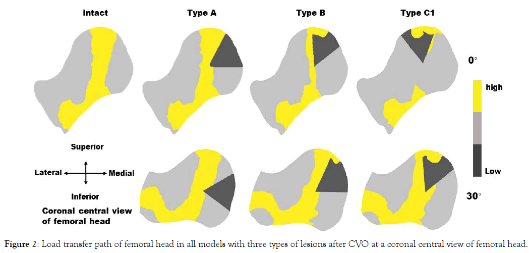
The load transfer path of femoral head was disrupted by the necrotic lesion, especially in type B and C1, and reconstruction of load transfer load was present after 30° CVO compared to the intact femoral head (Figure 2).

Figure 2. Load transfer path of femoral head in all models with three types of lesions after CVO at a coronal central view of femoral head.
Hip Contact Stress Changes after CVO
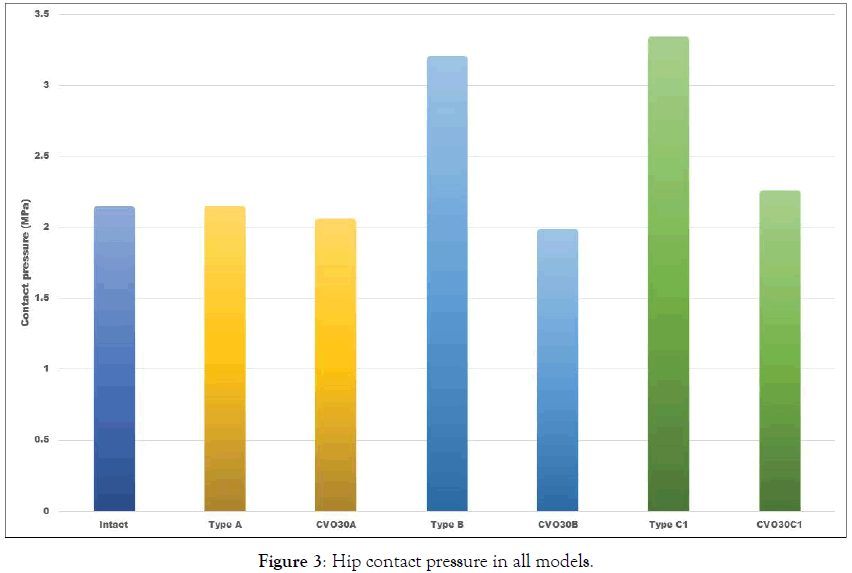
The hip contact stress in all the finite element models was evaluated by mechanical parameter of CPRESS (Figure 3). The intact hip contact stress was 2.13 MPa, for type A, B, C1, it was 2.13 MPa, 3.18 MPa, 3.32 MPa, and it was 2.04 MPa, 1.96 MPa, 2.24 MPa after 30° CVO, respectively.

Figure 3. Hip contact pressure in all models.
For validation of the finite element model, preferential longitudinal compressive-stress transmission through the primary trabeculation system of the femoral head across a coronal head midsection layer was simulated in intact hip model and it was interrupted by the necrotic lesion, which was consistent with the results of the report [10].
The hip contact pressure was elevated with femoral head necrosis [2], because the lesion can’t transfer the load to the lower limbs, more than that, the lesion with a weaken mechanical structure is prone to collapse in the load-bearing area. Therefore, the preserving hip joint methods for treatment of femoral head necrosis were developed according to different principles. Core decompression surgery reduces the hip joint pressure, promotes blood flow and encourage healing of the bone, which weakens the mechanical support however, tantalum rod techniques insert the tantalum rod devices into necrotic area, strengthening the load transfer for the femoral head from the results of the present study, for type A, the contact hip joint pressure was closed to the intact situation, and it didn’t change much even after the 30° CVO, and the lesion had a little influence on the load transfer path either before or after the osteotomy compared to the intact situation, it suggested that there was no much meaningful to perform the CVO in type A lesion, which was consistent with the clinical reports about CVO that there were no type A cases to be chosen for CVO [4,5,12,13]. For type B, the contact pressure was higher than the intact model, and declination of contact pressure was addressed after the osteotomy, the lesion interrupted load transfer path partly, which high stress was accumulated in the roof of necrosis, however, the load transfer path was reconstructed with a wider path after CVO, similarly, for type C1, the highest value of contact pressure was present, and closed to the intact situation after the osteotomy, at the same time, the lesion interrupted load transfer path largely with a narrower transfer path, however, it changed widely after the osteotomy, respectively.
The study was limited by the method that just a computational simulation was performed to predict the joint contact pressure and the load transfer path changes after CVO, it should be validated by some experimental measurement to compare the results of this prediction. Furthermore, the lack of a standardized definition for load transfer path of femoral head, in the study, just a highlighting stress flow was defined as the load transfer path with the intact model as a standard.
Conclusion was that the CVO can remove the lesion out of weightbearing area, which supported by the healthy bone, therefor; the load transfer path was widen, contributing to decrease the joint contact pressure.
Citation: Citation: Fenga WH, Zhang HH, Kanga Z (2001) Biomechanical Changes after Intertrochanteric Curved Varus Osteotomy for Femoral Head Necrosis: A Finite Element Simulation. Adv Tech Biol Med. 9:309. doi: 10.35248/2379-1764.21.9.309.
Received: 26-Jun-2021 Accepted: 15-Jun-2021 Published: 23-Jul-2021 , DOI: 10.35248/2379-1764.21.9.309
Copyright: ©2021 Fenga WH, et al. This is an open access article distributed under the term of the Creative Commons Attribution License, which permits unrestricted use, distribution, and reproduction in any medium, provided the original work is properly cited.