Journal of Geology & Geophysics
Open Access
ISSN: 2381-8719
ISSN: 2381-8719
Research - (2023)Volume 12, Issue 11
The presence of the coherent noise in the seismic data is a common problem to study the earth subsurface using seismic reflection datasets in offshore as well as onshore environments. The 2D Frequency-Wave number (F-K) and the Radial Trace Transform (RTT) techniques were used to suppress dispersive ground roll energy from high resolution onshore seismic data with a fold of 150 acquired from Gelana Basin in Southern Main Ethiopian Rift. Both the F-K and RTT techniques are based on local wave field decomposition to attenuate coherent noise from acquired seismic data. The objective of the study was to establish which of the techniques would attenuate the coherent dispersive ground rolls most effectively. Selected shot from the input seismic reflection data was subjected to a Fourier transform to display their amplitude spectra and phase spectrum to design the optimum parameters for F-K filtering of the whole shot. Thereafter both the F-K and RTT techniques were applied to the selected seismic line-12 from Gelena basin and this study showed both techniques efficiently attenuate coherent noise or ground roll. However, Radial Trace Transform (RTT) filtering technique the primary events or reflections are greatly enhanced and coherent noise trace including the air blast (sound waves) are seen better attenuated and no trace of background noise are observed unlike F-K suppression technique. From results obtained, the RTT was recommended as a better technique for coherent noise attenuation than the traditional 2D F-K domain technique.
Ground roll; Frequency-wave number; Radial trace transform; Coherent noise; Filtering; Attenuation
Onshore seismic data is subjected to a series of filtering because it is commonly contaminated with coherent noise such as ground roll, direct waves, diffractions and multiples. These noises generally, mask and interfere the depth subsurface signals or the primary events in seismic data [1]. A collection of surface waves generated by seismic source mostly known as Coherent noise or ground rolls essentially associated with surface wave (Rayleigh wave) with high amplitude, dispersive, low frequency and low velocity. Because of their dispersive nature, ground roll mask deep reflections at long offset and shallow reflections at short offset [2-4].
In seismic data processing several techniques are routinely applied to attenuate coherent noise with attempting to preserve the primary signals and their amplitudes. Some of these techniques include filtering in Frequency-Wave number (F-K) domain demonstrated by Yilmaz and Doherty [5], and the Radial Trace Transform (RTT) applied by Ottolini [6], Claerbout [2], and Henley [3]; these methods uses distinguishing characteristics such as frequency content and apparent move out are based on the possibility of separating the signal and noise [7].
In this study attenuation of coherent noise is done by Frequency- Wave number filtering (F-K Filtering). The Fourier transform provides the possibility of looking for sparse dominant energy harmonics of data, which often contain the desired seismic signals [8]. Gelana basin is part of southern main Ethiopian rift and seismic reflection data were acquired by Africa oil Ethiopia B.V. in 2014/15 based on the Petroleum Production Sharing Agreement with Ministry of Mines, Addis Ababa, Ethiopia (Figure 1) [9].

Figure 1: Locations of 2D-seismic lines on southern main rift valley basin of Ethiopia: Overlaid ALOS/PALSAR Digital Elevation Model (https://vertex.daac.asf.alaska.edu/), modified from [9]. Note: Vertex DEM (m): 


Overviews of the Geology
Tertiary rift system of Ethiopia is divided into three segments based on tectonic setting and period of rift propagations: Afar, the Main Ethiopian Rift (MER) and the Southern rift. Much of previous studies tries to classify the basins based on plate tectonic setting which is very important to understand the origin and development of sedimentary basins [10-15].
Previous subsurface structural study using full tensor gravity anomaly on the Gelana basin indicate that the area is affected by North-South trending faults [16]. Geological field study by Kebede et al. [17], shows that Amaro horst which is adjacent to Gelana basin is underlain by basement rocks, Cenozoic volcanic rocks, Quaternary and pre tertiary sediment. Exposed sections of pre-tertiary sediments-Mesozoic sediments (sandstone and Antalo and limestone units of the Adigrat Formation, etc.) are observed along the rift margin overlying unconformably on the Precambrian crystalline basement at Amaro Horst near Gelana basin and, Guraghe area, Kella horst, along the western margin of the rift systems [18-22].
The constrained full tensor gravity anomaly inversion [17], in Gelana basin shows that the total sediment thickness in Gelana basins exceeds 3500 m. Integrated seismic reflection study in Gelana basin [9], shows that the west tilted half graben geometry with the master fault on the western side, which confirmed the asymmetric architecture of Gelana basin obtained by geological cross section measured in the field by Ebinger et al. [23], (Figure 2) [9,24].

Figure 2: Geological map of Gelana basin and its surroundings modified from [9,24]. Note:  Lakes,
  Locations of rock samples,
  Faults,
  Lineaments.
Material
In this paper onshore 2D-seismic data are obtained from Ethiopian Ministry of Mines in SEG-D raw data format on Gelana basin and processed by Vista 2D/3D seismic data processing software for Linux System.
Schematic diagram of receiver station (Figure 3), and vibroseis (source) station (Figure 4), are presented below.

Figure 3: Receiver station configuration and Geophone/marshphone
array configuration. Note:  Receivers stations,
  Geophones.

Figure 4: Source (Vibroseis) station and array configuration. Note: Receivers stations,
  Geophones.
Receiver parameters: Type of receiver-geophones/marshphones, Model-Sensor SM-24, Type response-spike, natural frequency-10 Hz and interval receiver station-15 m.
Receiver array: Linear centered in station, geophone spacing-2.5 m and dimension-12.5 m (15 m effective).
Source parameters: Type of source-vibroseis, unit weight-57.800 lb, ground force-75 %, number of vibrators-3, source array-25.2 m, number of sweeps-2, type of sweep-linear, sweep frequency- upsweep 4-64 Hz and sweep length-16.
The acquired land seismic reflection data in the study area has a high resolution with a fold 150 given by the Eq.1;
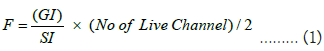
Where F is Fold, GI is Geophone Interval, SI Source Interval can be obtained from Table 1
| Receiver Land | |
|---|---|
| Spread 4492.5-7.5-0-7.5-4492.5 (Roll in, Roll out) | |
| Live channel | 600 |
| Receiver interval | 15 m |
| Source interval | 30 m |
| Geophones/Trace | 1 string of 6 Geophones |
| Geophone pattern | In-line linear |
| Geophone spacing | 2.5 m |
| Pattern length | 12.5 m |
Table 1: Land seismic data acquisition parameter.
Method
Attenuation of surface waves: 2D-Frequency–Wave numbers (FK) filtering; the raw seismic reflection dataset was transformed from conventional t-x domain to F-K domain by 2D-Fourier transform using Vista 2D/3D software. Fourier transform separates events according to their dips in the F-K domain in which the coherent noise is clearly distinguishable from the reflected datasets which are overlapped on t-x domain [7,25] (Figure 5).

Figure 5: Gelana basin raw record (shot) 143 of Line-12.
The 1-dimensional forward Fourier Transforms (FT) are defined as Eq.2;
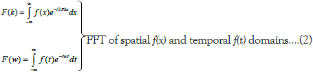
Where,  is distance, and k is wavenumber, where
 and λ is wavelength. We also use the shorthand notation introduced
by Ronald et al. [26]. These equations are more commonly
written in terms of time t and frequency ν where
and λ is wavelength. We also use the shorthand notation introduced
by Ronald et al. [26]. These equations are more commonly
written in terms of time t and frequency ν where  and t is the period. Therefore, in seismic data processing applying Finite
Fourier Transform (FFT) is the useful tool for transformation
from time and space domains (t-x) to the Frequency and Wave
number (F-K) domains in order to separate ground roll (surface
waves) from the reflected seismic data.
and t is the period. Therefore, in seismic data processing applying Finite
Fourier Transform (FFT) is the useful tool for transformation
from time and space domains (t-x) to the Frequency and Wave
number (F-K) domains in order to separate ground roll (surface
waves) from the reflected seismic data.
Linear events f(t,x) in the t-x domain can be described in the Eq.3;
f (t, x) = s(t)∗σ (t − tan(α )x + b)……… (3)
Where, the symbol “∗ ” reperesnts convolution with respect to variable time (t), s(t) is a seismic wavelete, (α) is the angle between the simulated linear event and the space axis and the constant b is the intercept of the event on the time axis.
The 2D-fourier transform is repersented by Eq.4;
F(ω, k) = S(ω)eiωbσ (k −ω tan(α )) ……… (4)
Where, S(ω) is the Fourier transform of the time function s(t) in Eq.3, the F-K filter was designed based on the property of 2D-Fourier transform in Eq.4, which is essential to remove the ground roll or coherent noise from the input seismic data. Truncation (rejection) zone was defined based on frequency in the F-K space to attenuate the ground roll. After the noise is truncated the data was transformed to t-x domain which is free from coherent noise.
The detail processing work flow or command flow used in Vista 2D/3D seismic reflection data processing software for attenuations of ground roll using 2D-Frequency–Wave numbers (F-K) technique is presented in the below Figure 6.

Figure 6: Frequency–Wave numbers (F-K) Filtering command flow used in Vista 2D/3D seismic reflection data processing software.
Radial Trace Transform (RTT) filtering: The radial trace transform was originally introduced by the Stanford Exploration Project [27]. The RTT transform extracts wave field amplitudes from a seismic trace panel, such as a shot or receiver gather, and interpolates them onto coordinates of velocity and travel time [28]. All the amplitude is intercepted by a particular trajectory are transferred in sequence to the new domain as a single radial trace in order to map seismic amplitudes from the shot gather to the radial trace domain and the process is repeated for each trajectory [3,27-30]. The radial trace transform R maps the amplitude of seismic trace S whose co-ordinates are source receiver offset X and two way travel time t to a new co-ordinate apparent velocity v and two way travel time t.
The transform is defined as Eq.5;
R{S(x,t)} = S '(v,t ') ……… (5)
With the invers given by Eq.6;
R−1{S '(v,t ')} = S(x,t) ……… (6)
Where t ' = t and 
The detail processing work flow or command flow used in Vista 2D/3D for attenuations of ground roll using Radial Trace Transform (RTT) technique is presented in the below Figure 7.

Figure 7: Radial Trace Transform (RTT) Filtering command flow used in Vista 2D/3D seismic reflection data processing software.
Figure 7, Radial Trace Transform (RTT) Filtering command flow used in Vista 2D/3D seismic reflection data processing software.
In this paper 2D Frequency-Wave number (F-K) and the Radial Trace Transform (RTT) techniques were used to suppress dispersive ground roll energy from high resolution onshore seismic data with a fold of 150 acquired from Gelana Basin in Southern Main Ethiopian Rift. The Frequency–Wave numbers (F-K) and Radial Trace Transform (RTT) filtering technique is applied to the same input seismic reflection data, that is, line-12, Shot 143, from the Gelana basin is used to enhance the primary reflections by attenuating the ground roll.
In seismic data processing the signal can be described equally well as in a time series (amplitude versus time) or as combination of an amplitude spectrum (amplitude versus frequency) and phase spectrum as shown in the (Figure 8). Frequency spectrum indicated that dominant frequency range is 5-70 Hz; lower frequencies below 5 Hz are not contributing any signal. Filter panel test is also performed on raw seismic data, the results on filter indicate that contribution of signal below 5 Hz and above 70 Hz had no significance.

Figure 8: Frequency analyses in raw seismic data shot 143 line 12.
To convert from time domain to frequency domain requires the use of Fourier transform and to change from frequency domain to time domain requires the use of inverse Fourier transform. For recently collected sampled or digital data simple and fast methods of transformation are utilized. These are known as Fast or Finite Fourier Transform (FFT) and Inverse Fast or Finite Fourier Transform (IFFT). Naghizadeh [31], has introduced an f-k domain method that utilizes information from all desired frequencies for robust interpolation or denoising of seismic data.
Frequency–Wave numbers (F-K) 2D filter design and implementation
In seismic signal analysis it is a common practice to transform the seismic data from time-space (t-x) domain to Frequency-Wave number (F-K) to clearly separate the coherent noise and to obtain the range of frequencies of the seismic data which are essential inputs to attenuate surface waves. The F-K domain has been frequently used for interpolation and denoising purposes and it is obtained by applying Fourier transforms along the time and space axes of the seismic data. The Fourier transform provides the possibility of looking for sparse dominant energy harmonics of data, which often contain the desired seismic signals [8].
One of the prominent attributes of the F-K domain is the separation of signals according to their dip. This property makes the F-K domain a suitable option for ground-roll elimination due to the distinctive dip information of ground roll. The range of frequency in the seismic data is from ~5Hz to ~70Hz (Figure 9). Note that the Signal is crossed by noise in the t-x Plane whereas; they are separated in the F-K plane (Figure 9).

Figure 9: T-X domain (left) and F-K domain (right) of Gelana basin Line-12, shot 143.
To mute and supress unwanted signals, coherent noise the optimum filter (Figure 9), was designed on both frequency and wave number basis. Even if the filter was designed to preserve low frequency signals between the wave number (k) ranges -0.1 to 0.2 which is imperative not to supress frequency below 12 Hz, between the wave number (k) range -0.1 to 0.2 useful primary signals of low frequency signals are muted or supressed. The result obtained in this study shows Frequency–Wave numbers (F- K) 2D Filter is capable of modelling the coherent noise or ground roll (Figure 10). However, after the F-K filtering operation the output data (Figure 11), still depicts the ground role and coherent noise are visible including the air blast or sound wave.

Figure 10: F-K predicted noise model for the unprocessed input data.

Figure 11: Output data after ground roll or coherent noise suppression using F-K domain Filter.
Radial Trace Transform (RTT) filter design and implementation
It seems that the Radial Trace Transform (RTT) technique effectively supress the ground roll or coherent noise including the air blast or sound wave (Figure 12). The noise model is generated in RTT domain (Figure 13), and the output filtered data is transformed into X-T domain. The result obtained in this study shows that the Radial Trace Transform (RTT) is more effective and efficient in supressing the ground roll or coherent noise than the conventional Frequency–Wave numbers (F-K) 2D filtering technique.

Figure 12: Output data after coherent noise suppression using RTT technique after transformed to the X-T model.

Figure 13: Noise model for the input data in RTT domain.
In the study two methods, that is, 2D-Frequency–Wave numbers (F-K) filtering and Radial Trace Transform (RTT) filtering are applied to attenuate the ground roll or coherent noise on onshore 2D-seismic reflection datasets acquired from Gelana basin in southern main Ethiopian rift. As demonstrated by previous scholars [3,28,29] for Radial Trace Transform (RTT) filtering and Yilmaz and Doherty [5], for Frequency–Wave numbers (F-K) filtering, this study showed both techniques efficiently attenuate coherent noise. However this study is aimed at comparing and contrasting the effectiveness or efficiency of the two techniques by applying on the display of the same shot gathers of Gelana basin raw record (shot) 143 of Line-12.
The result showed that F-K suppression technique still displayed the ground role or exhibited coherent noise including the air blast or sound wave which supressed the primary reflection data. However, Radial Trace Transform (RTT) filtering technique the primary events or reflections are greatly enhanced and coherent noise trace including the air blast (sound waves) are seen better attenuated and no trace of background noise are observed unlike F-K suppression technique. This result is also in agreement with previous study conducted by Adizua et al. [32]. Thus, Radial Trace Transform (RTT) technique is more effective and efficient in attenuation of ground role or coherent noise including the air blast and background noise which will lead to enhance the primary events than that of the Frequency–Wave numbers (F-K).
In the study two methods, that is, 2D-Frequency–Wave numbers (F-K) Filtering and Radial Trace Transform (RTT) filtering are applied to attenuate the ground roll or coherent noise on onshore 2D-seismic reflection datasets acquired from Gelana basin in southern main Ethiopian rift. The study able to confirm that the widely used 2D-Frequency–Wave numbers (F-K) Filtering to suppress the coherent noise on seismic shot gather is less efficient than that of not commonly used Radial Trace Transform (RTT) filtering method.
Citation: Kebede B (2023) Attenuation of Coherent Noise in Onshore Seismic Data of Gelana Basin using Radial Trace Transform and Wave Number Filtering: Southern Main Ethiopian Rift. J Geol Geophys. 12:1156.
Received: 30-Oct-2023, Manuscript No. JGG-23-27845; Editor assigned: 01-Nov-2023, Pre QC No. JGG-23-27845 (PQ); Reviewed: 15-Nov-2023, QC No. JGG-23-27845; Revised: 22-Nov-2023, Manuscript No. JGG-23-27845 (R); Published: 30-Nov-2023 , DOI: 10.35248/2381-8719.23.12.1156
Copyright: © 2023 Kebede B. This is an open-access article distributed under the terms of the Creative Commons Attribution License, which permits unrestricted use, distribution, and reproduction in any medium, provided the original author and source are credited