Journal of Biomedical Engineering and Medical Devices
Open Access
ISSN: 2475-7586
ISSN: 2475-7586
Research Article - (2023)Volume 8, Issue 1
For achieving a high accurate control and contamination-free medical gas, in this paper, a novel medical gas control system and the clean chamber technology are proposed. And with these technologies, a novel mechanical ventilator system based on the big data and cloud is introduced and discussed.
Control system, clean chamber, piston cylinder, mechanical ventilator, ICU, big data, cloud
Nowadays, mechanical ventilator is popularly served for patients to assist their breathing and improving the patients’ breathing quality. Since the first mechanical ventilator is invent and applied in 19th century [1,2]. The core structure involves from negative-pressure ventilator to positive pressure ventilator, which becomes the main design idea for our current mechanical ventilator because it is competent to control breathing accurately and effectively. Therefore, adequate relative jobs are completed and ongoing to improve the mechanical ventilator and extend the applications fields [3-7]. Due to the outstanding function, it assists doctors to save millions of patients’ life or improve their life quality in various diseases, such as ARDS, COVID-19.
In the popular positive-pressure mechanical ventilator, for achieving the high, adjustable flow control, the gas generator, the key component, is applied to generate a respiratory gas flow for the patient. By far, several mechanisms are employed to guide this design of the gas generator: Direct supply shown in Figure 1a, turbo shown in Figure 1b, and adjustable capacity chamber shown in Figure 1c and 1d. The direct supply means that regulate the pressure and flow rate from the gas source. Compared with other mechanisms, its structure is simple but it is hard to control tidal volume or inspiratory pressure accurately. The turbo, driven by electricity, has a smart size and is potentially able to supply a high flow rate. The adjustable capacity chamber includes two types: bellow shown in Figure 1c and piston cylinder shown in Figure 1d. The bellow separates the medical gas from ambient and part, so the gas mainly exposes to bellow. Besides, it can achieve a high accuracy control for tidal volume and inspiratory pressure. However, its structure is complicated and less maintainability. The piston cylinder, able to achieve an outstanding tidal volume and inspiratory pressure control as same as the bellow, has a relatively simple structure. But the medical gas saturates the inner space of the cylinder,therefore, it increases the contaminating probability derived from the piston cylinder [8,9].

Figure 1: Four types of gas generator mechanism a) direct supply; b) turbo; c) adjustable capacity chamber, bellow; d) adjustable capacity chamber, piston cylinder.
| Symbol | Definition |
|---|---|
| PS1 | Filter combination pressure sensor, O2 |
| PS2 | Filter combination pressure sensor, Medical air |
| PS7 | Filter combination pressure sensor, CDA |
| PV1 | Proportional valve, O2 |
| PV2 | Proportional valve, medical air |
| PV3 | Proportional valve, expiratory valve regulating |
| PS3 | Pressure sensor, chip, mixer |
| PS4 | Pressure sensor, chip, inspiratory airway |
| PS6 | Pressure sensor, chip, expiratory airway |
| FS3 | Pressure sensor, chip, expiratory patient circuit |
| OS1 | O2 SENSOR |
| RV1 | Pressure relief valve, 1.5 Psi |
| PR1 | Pressure regulator, handle |
| FS1 | Flow sensor, O2 |
| FS2 | Flow sensor, medical air |
| SV1 | 3/2 way valve, N.C., Connecting mixer, bag and inspiratory airway |
| SV2 | 3/2 way valve, N.O., Connecting to PS4 |
| SV3 | 3/2 way valve, N.O., connecting to ambient air, |
| Releasing more pressure in inspiratory airway | |
| PS5 | Pressure sensor, chip, PEEP |
| SV6 | 3/2 way valve, N.C., Nebulizer airway |
| SV5 | 3/2 way valve, N.O., Connecting to O2 |
| R1 | Orifice |
| R3 | Orifice |
| R2 | Orifice, 0.024" |
| SV7 | Actuator controller |
| MM1 | Actuator |
| FR1 | Filter combination |
| FR2 | Filter combination |
| FR3 | Filter combination |
| NVR1 | No return valve |
| NVR2 | No return valve |
| NRV3 | No return valve |
| DV1 | Expiratory valve |
| PS8 | Pressure sensor, chip, chamber |
| PC1 | Piston cylinder |
Table 1: Symbol definition in Figure 7
The driving method normally contains the pneumatics and electricity. For electricity, the servo motor is popular but the cost is rather higher than the pneumatics.
For those shortage, in this paper, a novel gas generator with an outstanding controlling character, no contamination, and low cost, is explored and discussed. Then one ideal mechanical ventilator based on big data and cloud network technology will described. The sections are summarized as below,
Firstly, a novel gas generator will be introduced. This gas generator includes clean chamber with airbag, adjustable-volume piston cylinder and linear actuator. They will be discussed with detail separately.
Then, an ideal mechanical ventilator, with this gas generator, is described. Also, the dig data and cloud network technology are explored in this ventilator [10].
High accurate gas generator
Basic description
The gas generator, in the mechanical ventilator, is applied to generate a respiratory flow with some specified mode (e.g. pressure control, volume control, etc.) according to the patient’s condition. For achieving a more stable, more accurately controlled, and quite flow, the piston technology is employed. This novel gas generator contains two airways and an adjustablecapacity piston cylinder and clean chamber with airbag.
Piston cylinder
The piston cylinder is used to generate the breathing flow and also controls the inspiratory pressure, flow rate. The piston cylinder is a mature technology and there exists huge reference materials available, so its design won’t be discussed here. However, due to the tidal volume error ΔVT, the diameter of the piston exists limitation. Assume that no compression for air, rigid bar connecting to actuator (Figure 2).
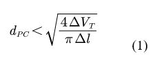
Where,
dpc—diameter of piston cylinder;
Δl—position accuracy for actuator, including repeatability, linear errors, etc.;
ΔVT—tidal volume errors, for this machine;
lPC—stroke of piton for piston cylinder.

Figure 2: Piston cylinder diagram.
For the structure of piston cylinder, the common solution is adopted and we won’t discuss here. The ideal piston cylinder structure is shown in Figure 3. There are two gas connecters. One of them is connected to exhaust and other one is connected to chamber [11].
Clean chamber with airbag
This clean chamber has two gas access ports, one of which is connected to PC1 and the other is connected with medical gas airway and the airbag, shown in Figure 4. The chamber can be designed as the vacuum chamber. The airbag fills the medical gas and separates other parts and the ambient. The thickness of the airbag wAB is so small that it can be ignored. So, the volume of airbag VAB and the of the medical gas in the airbag has the relationship volume below.

Figure 3: Ideal piston cylinder.

For the ideal gas, with the set tidal volume VT, VMG is depicted as follow:
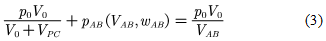
where,
V0—the sum of volumes of the chamber and connecting tube;
VPC—the volume of the piston cylinder PC1;
p0—atmosphere pressure in the chamber;
pAB(VAB, wAB)—the pressure caused by the inflating of airbag, relative to VAB and wAB.
If the small elastic material is applied to airbag, pAB (VAB, wAB) ≈0, so equation 3 is simplified as follow:
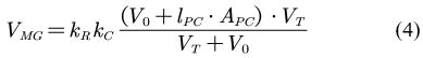
Where,
V0—the sum of volumes of the chamber and connecting tube;
APC—the section area of the piston cylinder PC1;
kR—modification coefficient, being used to compensate the VMG due to the residual gas in the airbag
kC—modification coefficient, being used to compensate the loss of VMG due to the actual air compression (Figure 4).

Figure 4: Chamber with airbag.
The ideal airbag should be similar as the plastic bag, with no or less elastic so that it is easier to control the tidal volume. The capacity of the airbag is theoretically equal to the max tidal volume (typically 2000 ml). Besides, because the quite high oxygen concentration, it is also expected to be oxygen resistance. Thirdly, this airbag can be used for 4 million cycles without any damage. The potential materials probably be rubber with low hardness, FTFE [12].
Control hardware
The gas generator, in the mechanical ventilator, is applied to generate a respiratory flow with some specified mode (e.g. pressure control, volume control, etc.) according to the patient’s condition. For achieving a more stable, more accurately controlled, and quite flow, the piston technology is employed. This gas generator contains two airways and an adjustablecapacity tank shown in Figure 5.

Figure 5: A novel high accuracy medical gas control system.
Two airways include medical gas airway (green) and pneumatic control airway (blue). The medical gas airway is used to transfer the gas for patient breathing. On the airway, Flow Sensors (FS1 and FS2) are applied to monitor the flow rates of the flow coming to the airbag and going to the patient separately. Non- Return Valves (NRV1 and NRV2) prevent the backflow, to force the flow to go from gas source to the patient. The Pressure Sensor PS2 monitors the inspiratory pressure. If the inspiratory pressure in the airway breaks the safety threshold, the relief valve RV1 will open and release more pressure until the pressure is lower than the safety value, thus preventing high pressure from hurting the patient’s lung. The pneumatic control airway provides power to drive the Linear Cylinder (LC1) to generate the reciprocation motion. The silencer SL1 is installed at the exhaust port of the controller to attenuate the noise produced by the Compressed Dry Air (CDA) [13].
The Adjustable-Capacity Tank (ACT, yellow) is composed of an airbag, a chamber, and a Piston-Cylinder (PC1). The chamber and PC1 connect each other with a tube, and the airbag connects to the medical airway. Such that, when the piston of PC1 does reciprocation, the capacity of the tank changes at the same time, so that the pressure in it changes too. Thus, the airbag will inflate or deflate. Due to the airbag, the medical gas is completely separate away from the contamination and bacteria derived from the ambient or other parts. The Pressure Sensor (PS1) on the chamber is used for monitoring the inner pressure of the chamber. The section area of the piston of PC1 is much larger than that in LC1, to adopt a smart LC1 with a shorter stroke. In other words, LC1 will occupy a smaller space. The controller drives LC1 to move accurately to adjust the capacity of the airbag-tidal volume or the inspiratory pressure (monitored by PS2).
The respiratory activity is divided into two steps: inhalation and exhalation.
Inhalation
Inhalation means that the medical gas is sucked into the airbag with LC1’s moving. When the piston of PC1 driven by LC1, moves right, the capacity of ACT turns big, due to the gas mass is constant, the pressure goes down. Because the pressure at the inlet is higher than it, the medical gas flows into the airbag and the bag inflates. At this time, the pressures at the left of NRV1 and the right of NRV2 are higher than the pressure between NRV1 and NRV2, so NRV1 shuts off and NRV2 opens, thus forcing the medical gas flow into the airbag rather than to the patient.
Exhalation
Exhalation, opposite as inhalation, the medical gas, sucked and stored in the airbag at the inhalation step, is extruded out of the airbag and pushed to the patient with LC1’s moving. When the piston of PC1 moves left, the capacity of ACT turns small, the pressure in it becomes higher so that the air extrude the airbag to make it small, thus the pressure in the airbag becoming higher. So, the pressure in the airway between NRV1 and NRV2 is higher than that of the other two sides. NRV2 shuts off and NRV1 opens. The gas flows through NRV1 and to the patient.
Control system
According to the different diseases and their symptom severity, generally speaking, several parameters, such as, tidal volume (VT), respiratory frequency (f), inspiratory time and expiratory time ratio (IE), positive pressure expiratory pressure (PEEP) and O2 concentration and inspiratory pressure (pin), are configurated and monitored. Specifically for the gas generator, VT, pin, and inspiratory time are controlled and monitored. Therefore, multi-closed-loop control strategy is employed to handle this process. There are many respiratory modes available for the mechanical ventilator. But fundamentally, which are mainly based on pressure control and volume control. Figure 6 depicts one typical multi-close control based on VT.

Figure 6: One typical control diagram for gas generator (control variable VT).
Mechanical ventilator based on MGHACS
The ideal mechanical ventilator diagram is shown in Figure 7. This ventilator requires three air sources: CDA (providing power to actuator MM1 for gas generator), O2 and medical air and supplies the functions including: adjustable respiratory and nebulizer [14].

Figure 7: Ideal mechanical ventilator system schematics (symbol refers to Table 1).
The control frame for this ventilator is described in Figure 8. The artificial intelligence (AI) system located in slave computer, operates valves and actuator to output safe and effective flow to patient based on programmed respiratory mode and monitors the various parameters in real time, such as pin. The user interface on the terminal provides standard operations and communicates with slave computer in real time. At the same time, all the data recorded in the terminal will uploaded to the cloud. Powered by big data analysis technology, the cloud can assist the specialist to make specified therapy. And the specialists can transfer the therapy remotely to the ventilator anywhere without space limitation, so that the patient can receive a quick-response, specified and low cost treatment.

Figure 8: Control frame of mechanical ventilator with cloud.
In this paper, a novel high-accuracy gas generator is proposed and discussed deeply. With this technology, a novel mechanical ventilator is described. Also, the big data and the network cloud is applied to this ventilator to improve the effectivity. With the development of network technology, medical treatment collaboration is becoming true. People can receive more and more skilled, specified, effective therapy with low affordable cost. In the future job, it is one our target Besides, for this airbag volume’ control model ignores the elastics of airbag, thus influencing the control accuracy. So, it is our another main job to optimize the airbag model with considering the airbag material elastics.
Citation: Zhao L (2023) A Novel Mechanical Ventilator Based On Novel High Accurate, Contemination-Free Gas Generator for ICU Environment. J Biomed Eng Med Dev. 8:252
Received: 18-Jun-2020, Manuscript No. BEMD-20-4998; Editor assigned: 22-Jun-2020, Pre QC No. BEMD-20-4998 (PQ); Reviewed: 02-Jul-2020, QC No. BEMD-20-4998; Revised: 22-Mar-2023, Manuscript No. BEMD-20-4998 (R); Published: 30-Mar-2023
Copyright: © 2023 Zhao L. This is an open-access article distributed under the terms of the Creative Commons Attribution License, which permits unrestricted use, distribution, and reproduction in any medium, provided the original author and source are credited.