

Indexed In
- Genamics JournalSeek
- JournalTOCs
- CiteFactor
- RefSeek
- Hamdard University
- EBSCO A-Z
- OCLC- WorldCat
- Publons
- Google Scholar
Useful Links
Share This Page
Journal Flyer

Open Access Journals
- Agri and Aquaculture
- Biochemistry
- Bioinformatics & Systems Biology
- Business & Management
- Chemistry
- Clinical Sciences
- Engineering
- Food & Nutrition
- General Science
- Genetics & Molecular Biology
- Immunology & Microbiology
- Medical Sciences
- Neuroscience & Psychology
- Nursing & Health Care
- Pharmaceutical Sciences
Research - (2019) Volume 8, Issue 1
Mathematical Modeling of Axial Oscillation Tools in High-Angle Wells
Emmanuel Omojuwa1*, Ramadan Ahmed1 and James Acquaye22Faculty of Mechanical Engineering, JA Oilfield Manufacturing, USA
Received: 17-Jan-2019 Published: 06-Feb-2019, DOI: 10.35248/2168-9873.19.8.316
Abstract
Experimental and field studies continue to demonstrate that downhole vibrations induced by axial oscillation tools (AOTs) in the drill string are the most efficient method for reducing friction and improving axial force transfer in high-angle and extended-reach wells. Modelling the dynamic response of AOT-involving drill string systems is of high importance for validating functional tests of oscillation tools and predicting their performance under downhole conditions. This study presents a mathematical model used for predicting the dynamic response of axial oscillationsupported drill string (AOSD) systems under the surface and downhole conditions. The model is useful to perform placement analysis of axial oscillation tools within the bottom hole assembly. Nonlinear equations of motion and introduction of displacement excitation in the model development make it different from existing models. The spring rate of the axial oscillation tool is a critical input in the determination of displacement excitation. The resulting nonlinear equations of motion are linearized, and solutions are obtained using the Eigenfunction Superposition method. The model is validated using published measurements obtained from experiments conducted using fieldscale axial oscillation tools. Results show reasonable agreement between predictions and measurements at different axial displacements, vibration frequencies, and system pressure drops. The usability of the mathematical model was validated with published experimental data with an observed average deviation of approximately 14.5%. Unlike existing models, the new model accounts for the combined effect of excitation pressure drop and vibration frequency on axial displacement.
Keywords
Axial vibrations; Oscillation tools; Borehole; Friction reduction; Modelling; Displacement excitation
Introduction
In directional drilling operations, specifically during slide drilling, frictional forces become substantial and impede the drill string motion, which leads to poor weight transfer to the drill bit. Frictional forces are developed due to the contact between drill string and borehole. The forced contacts are usually established by gravity acting in the lateral direction in deviated wellbores, drill string buckling (sinusoidal and helical), or hydraulic pressure imbalance which results in differential sticking. Extending the reach of high-angle-extended-reach wells through slide drilling is limited by high downhole friction due to poor weight transfer from surface to bit, ultimately leading to unstable tool face control, high stick-slip, high mechanical specific energy, low rate of penetration (ROP), excessive bit wear and increased drilling cost per foot (Figure 1) [1].

Figure 1: Inefficiencies caused by high frictional force in high-angle and extended reach wells.
Friction reduction along drill strings suppresses dynamic dysfunctions such as excessive torque and drag, buckling, whirling, and stick-slip, high Mechanical Specific Energy (MSE), thereby improving drilling efficiency and reducing Non-productive Time (NPT). Common and practical methods of friction reduction used to extend the reach of a directional well or increase weight transfer during slide drilling include: improving hole cleaning, adding lubricants to the mud, using non-rotating drill pipe protectors (NRDPPs), and applying downhole vibrating tools which dynamically excite the drill string and reduces friction [1,2]. The application of downhole vibrating tools for friction reduction, specifically the axial oscillation tools has turned out to be one of the most efficient method of improving weight transfer to the bit resulting in increase in rate of penetration (ROP) and extend reach of a well [3,4]. Axial oscillation tools reduce the frictional forces by generating axial displacement fluctuations. They have better friction reduction benefit than lateral vibration tools. The friction reduction benefit provided by lateral vibrations tools is significantly localized when compared to axial oscillation tools because axial vibrations propagate a greater distance up hole and downhole along the drill string.
Axial oscillation-supported drilling (AOSD) systems are drill strings, which consists of one or more axial oscillation tools (AOT) shown in Figure 2. The tools are in operation when circulating through the drill string. The effectiveness or performance quality of the tools can be measured using several key performance indicators such as improvement in the rate of penetration (ROP), reductions in mechanical specific energy (MSE) and stick-slip, and levels of weight transfer, friction reduction and tool-face control.

Figure 2: Axial oscillation-supported drilling system with AOT.
The dynamic model developed in this study is to simulate the response of the axial oscillation tool (AOT) during functional testing on the surface and downhole response of the axial oscillation-supported drilling systems. The goal of this study is to develop drill string dynamic model to determine the axial displacement and acceleration of axial oscillation tools as a function of magnitude of pressure pulses, frequency of pressure pulse (flow rate), elastic properties of the drilling assembly, AOT spring rate and damping mechanisms (viscous and Coulomb’s damping). Hence, the model will be used for functional testing of axial oscillation tools at the surface and for performance evaluation of tools while operating downhole (Figures 3 and 4).

Figure 3: Design of an axial oscillation tool.

Figure 4: Relative positions of the valve plates and generated pressure pulses.
The axial oscillation-supported drill string is modelled as an elastic continuous system of concentric cylindrical bars that deforms longitudinally. The equations of motion of a continuous cylindrical bar subjected to a displacement excitation source in a viscous medium with Coulomb friction are derived using the dynamic equilibrium approach. Unlike existing models, the dynamic response of the system is modelled considering AOT spring or displacement excitation. The resulting nonlinear equations of motion are linearized by using the equivalent viscous damping force to represent the damping forces and solved using the Eigenfunction superposition method. The developed mathematical model can be used to calculate natural frequencies, axial displacements, and accelerations of the system. The results from the model predictions are validated with the data obtained from functional testing of axial oscillation tools (AOTs) (Figure 5).

Figure 5: Shock tool or oscillation section of an axial oscillation tool (AOT).
Literature Review
Design and working mechanisms of AOT
The working mechanism of axial oscillation tools (AOTs) is the application of a fluid actuated positive displacement motor (PDM) and an associated valve assembly to provide pressure pulses to a shock-sub or oscillation section [5]. The axial oscillation tool comprises of three main sections: power section, valve section, and oscillation section. The power section is a positive displacement motor (PDM) powered by drilling fluid (or mud), creating an eccentric motion of the rotor. The eccentric rotor motion is transferred to the valve section located at the bottom of the power section. The fluid leaving the power section is directed towards the valve section, which contains orifices or valve plates. The varying path of the fluid flow with respect to the stationary output orifice creates pressure pulses or fluctuations. These pressure pulses are used as excitations of the pressure responsive device such as a shock-sub or oscillation section. Figure 3 shows the schematics of the design and working mechanism of a common axial oscillation tool.
The valve assembly consists of an oscillating valve (or eccentric orifice) and a stationary plate (or concentric orifice). The oscillating valve is coupled with the rotor, and the stationary plate is attached to the bottom sub at a fixed position. As the rotor rotates within the stator, the oscillating valve moves almost in linear motion called nutation, creating repeated or periodic restrictions in the flow path. The flow area between the stationary plate and oscillating valve generates cyclic change in the backpressure. The total flow area (TFA) repeatedly varies from minimum to maximum, creating pressure pulses inside the drill string [6]. The variation of TFA makes the valve section to be the heart of the axial oscillation tool (AOT). The pressure pulse inside the tool is high at minimum TFA and low at maximum TFA. Figure 4 shows the relative positions of the valve plates and generated pressure pulses during operation.
The frequency of the generated pressure pulse is directly proportional to the flow rate and rotor speed. Due to the rotor-stator lobes configuration, the pressure pulses generated within the power and valve sections have frequencies in the range of 9 to 20 Hz, depending on the flow rate and size of the tool. The pressure pulses are transmitted from the valve section to the shock tool or oscillation section (Figure 5) through the viscous fluid inside the string. The pressure pulses exert a hydraulic force on the pump open area (POA) of the oscillation section (shock tool), producing axial vibrating force at a predetermined frequency which travels up hole and downhole, along with the drill string, and maintaining dynamic condition to reduce friction between borehole and drill string.
Existing models
The theory of axial vibrations of drill strings is primarily used to model the response of axial oscillation-supported drilling systems subjected to excitation forces. A variety of analytical axial vibration models have been developed to investigate the axial vibrations of drill strings. This study focuses on pure axial oscillations and reviews uncoupled axial vibration models. A recent study [7] on drill string vibration models summarized the historical contributions of earlier modeling studies on axial vibrations in drilling systems. The AOSD systems have been modelled as a continuous elastic rod or discrete mass-spring vibration damper. Generally, the equations of motion for continuous systems are partial differential equations (PDE), and discrete systems are modelled using ordinary differential equations (ODE). Bailey, Finnie and Li modelled axial vibrations in drill strings using the undamped wave equation as the equation of motion. The natural frequencies (or Eigenvalues) and mode shapes are obtained by the method of separation of variables [8,9]. Fixed, free, or spring ended boundary conditions are considered at the bottom as recommended by Bailey and Finnie.
Some studies Tian et al. [10] modelled the drill string as a continuous system of stepped shafts. Khan derived a linear equation of motion with damping and force terms. The damping term in the linear equation of motion represents drillstring-wellbore frictional contact, fluid viscous effects, material damping, and radiation losses into the formation [11]. The natural frequencies and mode shapes were evaluated for three different boundary conditions (fixed at the top and bottom, fixed at the top and free at the bottom; mass-spring at top and spring at the bottom). The third boundary condition is considered the most realistic one because it accounts for the mass and stiffness of the draw works and derrick at the top [12,13]. The boundary condition with the spring at the bottom (i.e., bit) provides a means of varying the bottom end condition from fixed to free or to any intermediate value by varying the spring constant [14].
Li developed a model considering the wellbore-bit contact as a source of excitation in axial vibrations of drill string with no distance or velocity of slip between the bit tooth and the hole bottom. The source of excitation is modelled as a periodic and harmonic force which is expanded using Fourier series. Other studies modelled the source of excitation as frictional contact between the bit and borehole where a unit harmonic relative displacement is introduced at the bit. The influence of the mud on the dynamics of the drill string is modelled as an added mass and viscous damping distributed along the string. The transfer matrix method is used to solve the linear damped equation of motion with a force term.
Recent studies Barakat et al. [15] used a multi-degree of freedom discrete system (mass-spring) to model the bottom hole assembly (BHA) components, the axial oscillation tool, and the entire drill string. The equation of motion derived from the spring-mass discrete model is an ordinary differential equation with a linear viscous term. The viscous damping coefficient assumed by Forster is varied at different locations along the drill string model to match field data. The results obtained from the discrete model of Clausen show an increase in the acceleration response of the axial oscillation tool as the operating frequency increases, and high BHA acceleration at lower frequencies, which starts to reduce at higher frequencies. However, the reduction in BHA axial displacement and acceleration predicted at higher frequencies are not consistent with practical scenarios because there is a corresponding increase in excitation pressure when vibration frequency increases [16].
Shor used beam elements to model drill string components and mass-spring to model surface equipment. Linear viscous damping is assumed in the vertical section while nonlinear Coulomb damping (frictional contact) is considered in the curved and lateral sections. The equivalent viscous damping coefficient is utilized to represent both viscous and Coulomb damping and linearize the equation of motion. Results show that the magnitude of axial oscillations decreases when the AOT enters the lateral section due to increased normal force and higher Coulomb friction.
According to Tian, the axial vibrations generated by an AOT are transmitted in both axial directions (i.e., upward and downward) of the tool. The upward vibrations are propagated to the downward direction by the disc-spring installed in the upper section of the tool. Coulomb friction is considered in the axial vibration model of Tian. The excitation force generated by the axial oscillation tool is modelled as an axial force created by the change in flow area within the tool. The entire drill string is considered as a discrete multiple-degree-offreedom system and solved using a system of matrices. The results from the model are consistent with the experimental data.
Experimental studies
Axial vibrations developed due to different sources such as fluid hammer and axial oscillations of coiled tubing (CT) can improve axial force transfer. A number of experimental studies Dareing et al. [17] have been conducted to investigate the impact of vibration on axial force transfer and friction reduction. Barakat et al. performed experiments to determine the effect of hydraulic induced vibrations on the axial force transfer in horizontal wells. Parameters such as frequency, flow rate and axial loads were varied to investigate their effect on the force transfer. The vibration of horizontal drill string was generated by fluid hammer effects due to sudden opening and closing of a valve positioned on the drill string. Results show that hydraulic vibrations significantly improve axial force transfer. In addition, the results demonstrated a significant reduction (more than 30 percent) in friction force. The axial force transfer increased with water flow rate. The increase is similar to the effect of increase in the frequency of pressure pulses. Increasing the viscosity of water reduced axial force transfer due to the viscous damping, especially under laminar flow conditions. Although these results were obtained studying the effect of fluid hammer on force transfer, they can be used in the analysis of vibrations to improve axial force transfer and reduce friction along drill string.
The axial vibrations of coiled tubing (CT) drill string reduce friction considerably. An experimental study Paranjpe [18] conducted to investigate CT vibrations showed the effectiveness of vibrations in reducing friction and enhancing force transfer. The experiments were performed by placing 1 or 1-1/2 inches CT strings inside 2-7/8 inches CT. The experimental setup consists of a circulation pump, mud circulation tank, AOT power and valve section, shock tool and a linear displacement transducer, which was used to measure the average displacement of the mandrel of the AOT.
Often tools used to create downhole vibrations consume a significant level of hydraulic power, which increases the standpipe pressure. Excessive power requirement can be a limiting factor in the application of downhole vibrations tools. A recent field-scale experiment Bandstra [19] conducted on the agitator system (tool) demonstrated the effectiveness of low-pressure agitator systems and their performance. The design of the tool reduced the amount of pressure required to improve force transfer using axial oscillation systems. A more recent experimental study Leissa and Qatu [20] of the effect of axial oscillation on the rate of penetration (ROP) demonstrated the improvement of ROP at low vibrating frequencies, which could be due to the decreased amplitude of excitation at higher frequencies. Another study by Burnett et al. [21] indicated the development of pressure pulses/waves that are sinusoidal and can be represented by harmonics of Fourier trigonometric series.
Mathematical Modelling
This section presents the dynamic model, which is developed to simulate the response of axial oscillation-supported drilling (AOSD) systems subjected to vibrations during surface/functional testing and downhole operations.
Assumptions and limitations
The following assumptions are made in the development of the model presented in this study:
• The motion of the system is purely axial and uncoupled.
• The excitation and motion of the system are periodic and harmonic.
• The only excitation considered is generated by the AOT.
• Viscous and Coulomb damping are the only types of damping considered.
• Steady-state behaviour is considered due to the continuous action of the excitation force.
• The material is elastic and homogeneous. Linear elastic deformation is assumed.
• The hydrodynamic force due to the inertia of the internal fluid is not considered.
The new model is applicable for axial oscillation-supported drilling systems that use AOT for excitation; however, it cannot be used for the entire drill string length.
Model formulation
The oscillations generated by the AOT are transmitted up hole and downhole. The up-hole oscillations are primarily excitations generated by the longitudinal motion of the support (springs) while the downhole oscillations are excitations developed by the transmitted elastic force from upward oscillations. The oscillation-supported drill string system is modelled as a continuous concentric cylindrical bar (or rod) that can deform axially along the longitudinal axis. The support or displacement excitation model for up hole oscillations is presented in Figure 6.

Figure 6: Model for up hole oscillations (support or displacement excitation).
Figure 7 shows the free body diagram of a differential element with length dx and cross-sectional area A along the bar, which is subjected to an excitation force F(x,t) and distributed forces (external and internal). The axial forces acting on the cross sections of the differential element of the bar are given as P and P + dP with: vb

Figure 7: Differential element undergoing longitudinal or axial deformation.
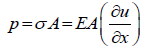 (1)
(1)
Where σ is the axial stress, E is Young’s modulus, u is the axial displacement, and ∂u/∂x is the axial strain. Damping force per length Fd and Coulomb friction Fc act on the differential element. Damping forces considered are due to the viscous medium surrounding the vibrating bar [22] and Coulomb or dry friction due to the wellbore contact with the cylindrical bar (Paranjpe, 1990). The boundary or end conditions of the model are dependent on the stiffness kf1, kf2 of the pipe and BHA fittings connected to the ends of the axial oscillation-supported drilling system.
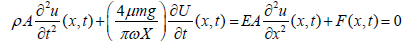
Using the dynamic equilibrium approach (Newton's second law of motion), the equation of motion of the longitudinal vibrations of the axial oscillation-supported drilling system is expressed as:
 (2)
(2)
The damping force per unit length, Fd=c∂u⁄∂t, is linear and proportional to the velocity, ∂u/∂t, where c is the viscous damping coefficient. The Coulomb damping force or frictional force occurs due to the contact between the cylindrical bar element and the borehole wall. The Coulomb frictional force is constant in value and independent of the magnitude of displacement and velocity; however, it depends on the friction factor μ and normal contact force, FN. The normal force (FN) is distributed along the cylindrical element. The Coulomb damping force acts in the opposite to the velocity of the element; and hence, it changes direction with the reversal of the element velocity. The Coulomb frictional force becomes discontinuous, when its direction changes. Thus, it is defined as:
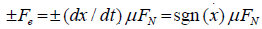 (3)
(3)
Where 
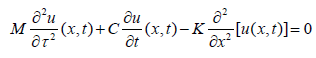
Simplifying Equation 2 and substituting for P using Equation 1:
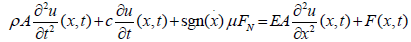 (4)
(4)
Equation 4 is the equation of motion for axial oscillation of a continuous concentric cylindrical bar subjected to an excitation force F (x, t) in a viscous medium with dry (Coulomb) friction. A closedform solution of Equation 4 is difficult to obtain analytically due to the inherent nonlinearity. The viscous damping term and nonlinear Coulomb friction force can be combined as an equivalent viscous damping force with equivalent viscous damping coefficient, ceq. This approach equates the dissipated amount of energy per cycle with nonlinear damping under steady state condition to the amount of energy dissipated per cycle with an equivalent viscous damping for a one-degree-of-freedom discrete system. Applying this approach, the equivalent viscous damping constant is determined [23]. The concept of the equivalent viscous damping assumes that although nonlinear damping is inherent in the system, its effect is relatively small, and the viscous solution is enough. Therefore, the equation of motion described in Equation 4 can be rewritten as:
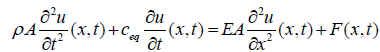 (5)
(5)
Equation 5 is the linear wave equation with damping and source terms. By substituting the equivalent viscous damping ceq derived in the Appendix, Equation 5 becomes:
 (6)
(6)
From the geometry of the continuous system, for up hole oscillations (support or displacement excitation) presented in Figure 6, the boundary conditions can be expressed as:
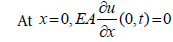 (7)
(7)
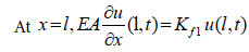 (8)
(8)
where kf1 is the stiffness of the pipes at the boundary of the model in Figure 6.
Analytical solution of linear wave equation
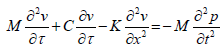
The equation of motion governing periodic support or displacement excitation of a continuous cylindrical bar subjected to damping (equivalent viscous damping) and longitudinal support excitation is expressed as:
 (9)
(9)
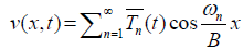
A particular solution of Equation 9 (steady-state response) is of interest to this study. A solution is obtained using the Eigenfunction Superposition Method [24]. Defining a new variable v(x,t) representing the displacement of any point in the bar relative to the support as:
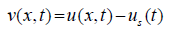 (10)
(10)
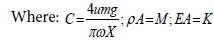
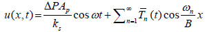
Where  δ is the displacement of
the AOT spring due to hydraulic excitation force (Fp) and AOT spring
rate (kg). The excitation force (Fp) is due to fluid pressure change (ΔP)
acting on the pump open area (Ap) pushing the springs or support
(Fp=ΔPAp). Therefore, Equation 11 becomes:
δ is the displacement of
the AOT spring due to hydraulic excitation force (Fp) and AOT spring
rate (kg). The excitation force (Fp) is due to fluid pressure change (ΔP)
acting on the pump open area (Ap) pushing the springs or support
(Fp=ΔPAp). Therefore, Equation 11 becomes:
 (11)
(11)
For simplicity, the term ![]() in equation 11 is ignored because
damping does not restrict the equivalent load induced by the support
motion. Also, the support or spring is not damped. Expanding the
periodic harmonic equivalent loading induced by the support motion
in equation 11 is ignored because
damping does not restrict the equivalent load induced by the support
motion. Also, the support or spring is not damped. Expanding the
periodic harmonic equivalent loading induced by the support motion  into a Fourier cosine series:
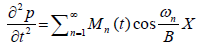 (12)
(12)
where: Mn(t)=Rn cosωt and Rn is the Fourier coefficient representing the amplitude of each component of the equivalent loading. The coefficient is expressed as:
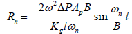 (13)
(13)
The solution of Equation 11 is assumed to be of the form:
 (14)
(14)
where  is the time-dependent solution due to longitudinal
support motion. Substituting the partial derivatives vt , vtt , vx and vxx and
is the time-dependent solution due to longitudinal
support motion. Substituting the partial derivatives vt , vtt , vx and vxx and![]() into Equation 11:
into Equation 11:
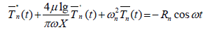 (15)
(15)
The particular solution of the ODE in Equation 15 is assumed to be of the form:
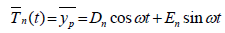 (16)
(16)
The constants Dn and En can be expressed as:
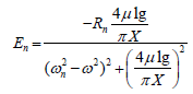 (17)
(17)
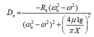 (18)
(18)
In another form, the particular solution or steady-state response in
Equation 16 can be expressed in terms of an amplitude  and a phase
angle
and a phase
angle 
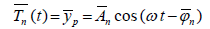 (19)
(19)
where 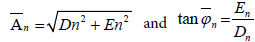 . The longitudinal
oscillating motion of a bar subjected to damping and longitudinal
support motion can be expressed as:
. The longitudinal
oscillating motion of a bar subjected to damping and longitudinal
support motion can be expressed as:
 (20)
(20)
Model Validation and Numerical Results
Model validation
The support excitation model developed has been applied to the results obtained from the functional tests [25] published in the literature. The input parameters for the functional testing of the first AOT (AOT-1) performed by Burnett are displayed in Table 1. During the experiment, the vibration of the drill string was generated by a sudden opening and closing of a valve positioned on the string. The experimental setup consisted of a shock sub with freely moving inner pipe clamped to a load transducer that is attached to the sub for measuring the axial load. The differential pressure across the tool was measured using pressure sensors installed upstream and downstream of the tool. During the test, the differential pressure linearly increased with flow rate.
| Parameters | Values | Units |
|---|---|---|
| Length, l | 2.13 | m |
| Average Outer Diameter, do | 0.16 | m |
| Average Inner Diameter, di | 0.07 | m |
| The stiffness of pipe fittings kf1, kf2 | 17.5 | MN/m |
| Modulus of Elasticity, E | 200 | GPa |
| Density of Steel, ρ | 7,861 | kg/m3 |
| Excitation or operating frequency , ω | 9.5-19 | Hz |
| AOT Pressure Drop/Backpressures, ΔP | 1.93-6.20 | MPa |
| AOT Spring Rate, kS | 6.13 | MPa |
| Pump open area, Ap | 0.01 | m2 |
Тable 1: Input parameters for functional testing of AOT-1.
The new model is used to predict the amplitude of oscillations. The predictions are compared with the average measured displacement from the functional test of AOT-1. Figure 8 presents measured and predicted axial displacements (i.e., amplitudes of vibration) as functions of the flow rate, which is directly related to the operating frequency of the tool. The discrepancies between the measurements and predictions increase (from 5.6 to 22%) with flow rate. In general, model predictions are slightly higher than the measurements. The discrepancies could be attributed to the coupling motion of the oscillation tool or underestimation of the friction and viscous damping.

Figure 8: Model vs. test data for AOT-1.
The input parameters used for the functional testing of the second tool (AOT-2) performed by Tian is presented in Table 2. The experimental setup for the functional test was comprised of plunger pumps, "hydro-oscillator" tool (AOT), shock absorber, test-sensor, throttling valves, and inlet and outlet pipes. Each experiment lasted for two minutes. Test measurements were compared with predictions of an analytical model developed in the study. The model predictions were found to be consistent with the experimental measurements. The amplitude of axial displacement and accelerations calculated from the new model are compared (Figure 9) with the experimental measurements and analytical results published by Tian. The model shows reasonable agreement with the experimental measurements.

Figure 9: Comparison of model predictions with measurements: (a) Displacement amplitude; and (b) Acceleration.
Parametric study
Using the new model, a parametric study is performed to examine the impact of different influential parameters such as friction factor and distance from the oscillation tool on the amplitude of vibrations. The axial or longitudinal response equation (Equation 20) is used to predict the response of an axial oscillation-supported drill string (Table 3), which is similar to the case considered in a previous finiteelement- based vibration modelling study [26]. The BHA and the input parameters of an axial oscillation tool (AOT-3) considered in the parametric study are presented in Table 4.
| Parameters | Values | Units |
|---|---|---|
| Length, | 4.72 | m |
| Average Outer Diameter, | 0.11 | m |
| Average Inner Diameter, | 0.07 | m |
| Stiffness of pipe fittings, , | 17.5 | MN/m |
| Modulus of Elasticity, | 210 | GPa |
| Density of Steel, | 7,861 | kg/m3 |
| Excitation or operating frequency , | 6.07 | Hz |
| AOT Pressure Drop/Backpressures, | 3.2 | MPa |
| AOT Spring Rate, | 4.5 | MN/m |
| Pump open area, | 0.006 | m2 |
| Friction coefficient | 0.2 | -- |
Table 2: Input parameters for functional testing of AOT-2.
| Parameters | Values | Units |
|---|---|---|
| Length, | 457.2 | m |
| The stiffness of pipe fittings, , | 26.3 | MN/m |
| Modulus of Elasticity, | 210 | GPa |
| Density of Steel, | 7,861 | kg/m3 |
| Excitation or operating frequency , | 19 | Hz |
| AOT Pressure Drop/Backpressures, | 5.86 | MPa |
| AOT Spring Rate, | 6.12 | MN/m |
| Pump open area, | 0.010 | m2 |
| Friction coefficient | 0.1-0.3 | -- |
Table 4: Input parameters for functional testing of AOT-3.
The new model is utilized to calculate the axial displacements (i.e., amplitude of oscillations) at 0 ft, 500 ft and 1,000 ft from the AOT towards the surface for different friction factor values (0.2, 0.5 and 1.0). It should be noted that the model of Gee et al. (2015) used a similar BHA (Table 3) and the operating frequency of 20 Hz. However, they used an arbitrary input force of 115 KN. Based on functional testing, at an operating frequency of 20 Hz, the tested axial oscillation tool (AOT) generated a pressure drop of 5.5 to 6.2 MPa, which displaced the spring by about 10 mm. The axial displacement responses for the BHA at different values of friction factors are presented in Figure 10. As anticipated the axial displacement response of the drill string reduces with the distance from AOT. The reduction is mainly due to the dissipation of vibrating energy along the length of the drill string. The increase in friction factor along the length of drill string has a minor effect on the amplitude of axial displacement. In vibration studies, the friction factor is a simplistic representation of drill string-wellbore contact and borehole conditions, which does not strongly affect the axial displacement and acceleration of the drilling system. Because the equivalent viscous damping force in equation 6 is more dependent on the length and mass of the drill string than the friction factor. This is consistent with previously reported model predictions [27] for AOT supported drilling string systems.

Figure 10: Predicted axial displacement response at different locations of the drill-string for various friction values: μ=0.2; μ=0.5; and μ=1.0.
| No. | String Component | OD (in) | OD (mm) | ID (in) | ID (mm) | Component Length (ft) |
Component Length (m) |
Cumulative Length (ft) |
Cumulative Length (m) |
|---|---|---|---|---|---|---|---|---|---|
| 1 | Bit | 8.50 | 216 | 2.25 | 57 | 0.85 | 0.26 | 0.85 | 0.26 |
| 2 | Motor | 6.75 | 171 | 4.75 | 121 | 25.30 | 7.71 | 26.15 | 7.97 |
| 3 | Float Sub | 6.75 | 171 | 2.75 | 70 | 3.15 | 0.96 | 29.30 | 8.93 |
| 4 | UBHO | 6.75 | 171 | 3.10 | 79 | 3.00 | 0.91 | 32.30 | 9.85 |
| 5 | 2 x NMDC | 6.63 | 168 | 3.25 | 83 | 60.00 | 18.29 | 92.30 | 28.13 |
| 6 | Flex Joint | 6.75 | 171 | 3.00 | 76 | 7.00 | 2.13 | 99.30 | 30.27 |
| 7 | Crossover Sub | 6.75 | 171 | 3.00 | 76 | 3.00 | 0.91 | 102.30 | 31.18 |
| 8 | 81 x Drillpipe | 5.00 | 127 | 4.28 | 109 | 2400.00 | 731.52 | 2502.30 | 762.70 |
| 9 | AOT-3 | 6.75 | 171 | 2.81 | 71 | 14.00 | 4.27 | 2516.30 | 766.97 |
| 10 | DP to Surface | 5.00 | 127 | 4.28 | 109 | 10696.00 | 3260.14 | 13212.30 | 4027.11 |
Table 3: Component of drill-string (baseline) used for parametric study.
| Parameters | Values | Units |
|---|---|---|
| Length, | 457.2 | m |
| The stiffness of pipe fittings, , | 26.3 | MN/m |
| Modulus of Elasticity, | 210 | GPa |
| Density of Steel, | 7,861 | kg/m3 |
| Excitation or operating frequency , | 19 | Hz |
| AOT Pressure Drop/Backpressures, | 5.86 | MPa |
| AOT Spring Rate, | 6.12 | MN/m |
| Pump open area, | 0.010 | m2 |
| Friction coefficient | 0.1-0.3 | -- |
Table 4: Input parameters for functional testing of AOT-3.
The plot of pressure drops and amplitude of axial displacement versus frequency at 500 ft from AOT and friction factor of 0.2 is shown in Figure 11. As the operating frequency increases, amplitude of axial displacement increases due to the corresponding increases in pressure drop. Previous modelling studies by Rao [28] show a decrease in axial displacement as frequency increases because they do not account for the corresponding increase in pressure drop [29].

Figure 11: Measured pressure differential (a) and axial displacement (b) vs. vibration frequency (friction factor=0.2; L= 500 feet).
The stiffness of the drill string can have some impact on the response of an AOT. Changing the drill string components to a stiffer and heavier assembly (Table 5) by replacing 32 drill pipe joints above the AOT-3 with heavy-weight drill pipe, it can be observed (Figure 12) that the amplitudes of axial displacement of the stiff string is slightly lower than that of the baseline (Table 3) at different values of friction factors [30]. The natural frequency increases with the stiffness of the drill string. The response equation (Equation 20) shows a reduction in the axial displacement with the natural frequency of the drill string. Hence, the slight reduction in axial displacement observed in the stiffer assembly (Figure 12b) is due to the small increase in the natural frequency of the drill string [31].

Figure 12: Comparison of the amplitude of axial displacement for different drill-string stiffness’s: (a) baseline; and (b) stiff string.
| No. | String Component | OD (in) | OD (mm) | ID (in) | ID (mm) | Component Length (ft) |
Component Length (m) |
Cumulative Length (ft) |
Cumulative Length (m) |
|---|---|---|---|---|---|---|---|---|---|
| 1 | Bit | 8.50 | 216 | 2.25 | 57 | 0.85 | 0.26 | 0.85 | 0.26 |
| 2 | Motor | 6.75 | 171 | 4.75 | 121 | 25.30 | 7.71 | 26.15 | 7.97 |
| 3 | Float Sub | 6.75 | 171 | 2.75 | 70 | 3.15 | 0.96 | 29.30 | 8.93 |
| 4 | UBHO | 6.75 | 171 | 3.10 | 79 | 3.00 | 0.91 | 32.30 | 9.85 |
| 5 | 2 x NMDC | 6.63 | 168 | 3.25 | 83 | 60.00 | 18.29 | 92.30 | 28.13 |
| 6 | Flex Joint | 6.75 | 171 | 3.00 | 76 | 7.00 | 2.13 | 99.30 | 30.27 |
| 7 | Crossover Sub | 6.75 | 171 | 3.00 | 76 | 3.00 | 0.91 | 102.30 | 31.18 |
| 8 | 81 x Drillpipe | 5.00 | 127 | 4.28 | 109 | 2400.00 | 731.52 | 2502.30 | 762.70 |
| 9 | AOT-3 | 6.75 | 171 | 2.81 | 71 | 14.00 | 4.27 | 2516.30 | 766.97 |
| 10 | HWDP | 5.50 | 140 | 4.28 | 109 | 1000.00 | 304.80 | 3516.30 | 1071.77 |
| 11 | DP to Surface | 5.00 | 127 | 4.28 | 109 | 9696.00 | 2955.34 | 13212.30 | 4027.11 |
Table 5: Component of stiff drillstring used for comparison.
Discussion and Conclusion
In this study, a new mathematical model for support or displacement excitation is developed. The model accounts for the spring rate or stiffness axial oscillation tools. The axial or longitudinal response equations developed in this study are used to compute the natural frequencies and axial displacement of axial oscillation-supported drilling systems using both functional test and downhole operating parameters. The following conclusions can be drawn from the results of the new model:
• For the same input data (pressure drop ~ 850 psi and frequency ~ 19 Hz), model predictions show that the displacements of functional tests are larger than that of the downhole tool. This is due to the inclusion of the equivalent viscous damping factor in the response equations. Therefore, under downhole conditions, the magnitude of axial displacements and accelerations generated by axial oscillation tools are lower than that of a functional test performed at the surface.
• Consistent with measurements, the model predicted axial displacement increased with flow rate (or frequency). This result is a good representation of reality and a valuable output from the model.
• As expected, the magnitude of the axial displacement generated by axial oscillation tools (AOT) reduces along the drillstring as it moves away from the AOT due to energy dissipation resulting from viscous and Coulomb damping.
• Stiffness and weight of the drillstring are essential parameters that can be used to control and optimize the dynamic response of axial oscillation tools.
REFERENCES
- Samuel R. Friction factors: What are they for torque, drag, vibration, drill ahead and transient surge/swab analyses?. IADC/SPE Drilling Conference and Exhibition. 2010;2:145-146.
- Newman KR, Burnett TG, Pursell JC, Gouasmia O. Modeling the effect of a downhole vibrator. SPE/ICoTA Coiled Tubing & Well Intervention Conference and Exhibition. 2009.
- Barakat ER. An experimental study and modelling of the effect of hydraulic vibrations on axial force transfer in horizontal wellbores. Report prepared for TUDRP Advisory Board Meeting, Tulsa, Oklahoma, USA. 2005.
- McCarthy JP, Stanes B, Clark K, Rebellon JE, Leuenberger G. A step change in drilling efficiency: Quantifying the effects of adding an axial oscillation tool within challenging wellbore environments. SPE/ IADC Drilling Conference and Exhibition. 2009.
- Eddison AM, Hardie R. Downhole flow pulsing apparatus. United States Patent. 2001;p:6279670.
- Baez F, Alali A. Drilling performance improvements in gas shale plays using a novel drilling agitator device. North American Unconventional Gas Conference and Exhibition. 2011.
- Ghasemloonia A, Rideout DG, Butt SD. A review of drill-string vibration modelling and suppression methods. J Petrol Sci Eng. 2015;131:150-164.
- Bailey JJ, Finnie I. An analytical study of drill-string vibration. J Eng Ind. 1960;82:122-127.
- Khan KZ. Longitudinal and torsional vibration of drill strings. Arch Eng. 1983;pp:1-61.
- Tian J, Yang Z, Li Y, Yang L, Wu C. Vibration analysis of new drill string system with hydro-oscillator in horizontal well. JMST. 2016;30:2443-2451.
- Rashed G, Ghaja R, Hashemi SJ. An analytical model for drill-string axial vibration. Presented at the 14th International Congress on Sound & Vibrations, Cairns, Australia. 2007.
- Lee HY. Drillstring axial vibration and wave propagation in boreholes. MIT. 1991;pp:1-167.
- Clausen JR, Schen AE, Forster I, Prill J, Gee R. Drilling with induced vibrations improves rope and mitigates stick/slip in vertical and directional wells. IADC/SPE Drilling Conference and Exhibition. 2014.
- Shor RJ, Dykstra MW, Hoffmann OJ, Coming M. For better or worse: Applications of the transfer matrix approach for analyzing axial and torsional vibration. SPE/IADC Drilling Conference and Exhibition. 2015.
- Barakat E, Miska S, Yu M, Simionescu PA, Takach N. The effect of hydraulic vibrations on initiation of buckling and axial force transfer for helically buckled pipes at simulated horizontal wellbore conditions. Proceedings of SPE/IADC Drilling Conference. 2007.
- Schultz R. Vibratory downhole tool technologies with application to horizontal drilling and casing installation. 2013.
- Dareing DW, Livesay BJ. Longitudinal and angular drill-string vibrations with damping. J Eng Ind. 1968;90:671-679.
- Paranjpe RS. Dynamic analysis of a valve spring with a coulombfriction damper. J Mech Design. 1990;112:509-513.
- Bandstra JP. Comparison of equivalent viscous damping and nonlinear damping in discrete and continuous vibrating systems. J Vib Acoust Stress Reliab Des. 1983;105:382-392.
- Leissa AW, Qatu MS. Vibrations of continuous systems, second edition. McGraw-Hill. 2011;2:1.
- Burnett T, Gee R, Martinez J, Carson CR, Canuel LAP. New technology enables rigs with limited pump pressure capacity to utilize the latest friction reduction technology. SPE Eastern Regional Meeting. 2013.
- Gee R, Hanley C, Hussain L, Canuel L, Martinez J. Axial oscillation tools vs. lateral vibration tools for friction reduction – what's the best way to shake the pipe?. SPE/IADC Drilling Conference and Exhibition. 2015.
- Alali A, Barton S, Mohanna A. Unique axial oscillation tool enhances performance of directional tools in extended reach applications. Brasil Offshore. 2011.
- Azike-Akubue V, Barton S, Gee R, Burnett TG, Alali A. Agitation tools enables significant reduction in mechanical specific energy. SPE Asia Pacific Oil and Gas Conference and Exhibition. 2012.
- Barton S, Baez F, Alali A. Drilling performance improvements in gas shale plays using a novel drilling agitator device. North American Unconventional Gas Conference and Exhibition. 2011.
- Forster I. Axial excitation tool string modeling. Conference Paper. 2015.
- Kragjcek RH, Al-Dossary AS, Koth WG. Successful application of new sliding technology for horizontal drilling in Saudi Arabia. 2011.
- Rao SS. Vibration of continuous systems, first edition Wiley, Hoboken, New Jersey. 2007.
- Robertson L, Mason CJ, Sherwood AS, Newman KR. Dynamic excitation tool: Developmental testing and ctd field case histories. SPE/ICoTA Coiled Tubing Conference and Exhibition. 2004.
- Strauss WA. Partial differential equations: An introduction, second edition. Hoboken, New Jersey: John Wiley & Sons, Inc. 2008.
- Wilson JK, Noynaert SF. Inducing axial vibrations in unconventional wells: New insights through comprehensive modeling. SPE/IADC Drilling Conference and Exhibition. 2017.
Citation: Omojuwa E, Ahmed R, Acquaye J (2019) Mathematical Modeling of Axial Oscillation Tools in High-Angle Wells. J Appl Mech Eng 8: 316. doi: 10.35248/2168-9873.19.8.316
Copyright: © 2019 Omojuwa E, et al. This is an open access article distributed under the term of the Creative Commons Attribution License, which permits unrestricted use, distribution, and reproduction in any medium, provided the original author and source are credited.